Page 3095 of 4264

pressure
gauge
abnormally
high Reduced or no air flow through
the condenser
��
Condenser clogged o")
HEATER AND AIR CONDITIONING 1-85
RESULT SYMPTOM TROUBLE CAUSE CORRECTION
Discharge
(High)
pressure
gauge
abnormally
high Reduced or no air flow through
the condenser
��
Condenser clogged or dirty
��
Radiator (condenser) fan
does not operate properly ��
Clean
��
Check cooling fan
operation
No bubbles in sight glass when
condenser is cooled by water
(Insufficient cooling)
��Excessive refrigerant in
system
��Check sight glass.
(See “Reading Sight
Glass”)
��
Discharge and
recover refrigerant.
Recharge to specified
amount
After stopping air conditioning,
pressure drops approx. 196 kPa
(2.0kg/cm
2 / 28 PSI) quickly ��
Air in system
��
Evacuate and charge
refrigerant system
Discharge
(High)
pressure
gauge
abnormally
low Insufficient cooling and excessive
bubbles in the sight glass
��
Insufficient refrigerant in
system
��
Check sight glass.
(See “Reading Sight
Glass”)
��Check for leaks
��
Discharge and
recover refrigerant.
Recharge to specified
amount
Low pressure gauge indicates
vacuum ��
Clogged or defective
expansion valve ��
Replace the
expansion valve
Frost or dew on refrigerant line
before and after receiver/ drier or
expansion valve, and low pres-
sure gauge indicates vacuum ��Restriction caused by debris
or moisture in receiver/drier
��Check system for
restriction and
replace receiver/drier
After turning off air conditioning,
high and low pressure gauge
balanced quickly
��
Compressor seal defective
��
Poor compression due to
defective compressor
gasket ��
Replace or repair
compressor
Suction
(Low)
pressure
gauge
abnormally
high Low pressure gauge is lowered
after condenser is cooled by
water
��
Excessive refrigerant in
system
��
Discharge and
recover refrigerant
Recharge to specified
amount
Low pressure hose temperature
around the compressor refrigerant
line connector is lower than
around evaporator
��
Unsatisfactory valve
operation due to defective
temperature sensor of
expansion valve
��
Expansion valve opens too
long ��
Replace the
expansion valve
After turning off air conditioning,
high and low pressure gauge is
balanced quickly ��
Compressor gasket is
defective
��
Replace
Air conditioning turns off before
passenger compartment is
sufficiently
cool ��Electronic thermostat
defective
��Check the electronic
thermostat and
replace as necessary
* For the charging and discharging operations in the table above, refer to “RECOVERY, RECYCLING,
EVACUATION AND CHARGING” in this section.
Page 3117 of 4264
WORKSHOP MANUAL
TF SERIES
MANUAL TRANSMISSION
(MSG MODELS)
SECTION 7B
Page 3119 of 4264

TABLE OF CONTENTS
PAGE
Main Data and Specifications .................................................................................")
MSG MODEL 7B-1
SECTION 7B
MANUAL TRANSMISSION
(MSG MODELS)
TABLE OF CONTENTS
PAGE
Main Data and Specifications .................................................................................... 7B - 2
General Description.................................................................................................... 7B - 3
Torque Specification .................................................................................................. 7B - 4
Repair Kit .................................................................................................................... 7B - 6
Removal and Installation ........................................................................................... 7B - 7
Disassembly ............................................................................................................... 7B - 15
Inspection and Repair ............................................................................................... 7B - 25
Reassembly ................................................................................................................ 7B - 29
Special Service Tool .................................................................................................. 7B - 42
Page 3125 of 4264

MSG MODEL 7B-7
REMOVAL AND INSTALLATION
Read this Section carefully before performing any removal and installation procedure. This Section gives you
important points as well as the order of operation. Be sure that you understand everything in this Section before
you begin.
Important Operations - Removal
Battery Cable
Disconnect the negative (-) cable from the battery terminal.
Engine Hood
Apply setting marks to the engine hood and the engine hood
hinges before removing the engine hood.
Gear Shift Lever
1. Place the gear shift lever in the neutral position.
2. Remove the gear shift lever knob.
3. Remove the front console assembly.
4. Remove the gear shift lever grommet and dust cover.
5. Remove the gear shift lever cover bolts.
6. Remove the gear shift lever.
Note:
Cover the shift lever hole to prevent the entry of foreign
material into the transmission.
Lifting the Vehicle
1. Jack up the vehicle.
2. Place chassis stands at the front and the rear of the
vehicle.
Transmission Oil Draining
1. Remove the transmission oil drain plug.
2. Replace the drain plug after draining the oil.
Page 3163 of 4264
WORKSHOP MANUAL
TF SERIES
MANUAL TRANSMISSION
(MUA MODELS)
SECTION 7B1
Page 3165 of 4264

Service Precaution ...............................................................")
MANUAL TRANSMISSION 7B1-1
SECTION 7B1
TRANSMISSION
MANUAL TRANSMISSION MUA
CONTENTS
PAGE
MUA (4�
�� �
2)
Service Precaution .......................................................................................................... 7B1 – 3
General Description ........................................................................................................ 7B1 – 4
Rear Oil Seal (4�
�� �2) ........................................................................................................... 7B1 – 5
Transmission (4�
�� �2) ......................................................................................................... 7B1 – 7
Disassembled View ..................................................................................................... 7B1 – 7
Removal ....................................................................................................................... 7B1 – 8
Installation ................................................................................................................... 7B1 –12
Transmission Case .......................................................................................................... 7B1 –18
Major Component ........................................................................................................ 7B1 –18
Disassembly ................................................................................................................ 7B1 –19
Reassembly ................................................................................................................. 7B1 –20
Intermediate Plate with Gear Assembly, Detent, Shift Arm, Shift Rod,
and Interlock Pin ........................................................................................................... 7B1 –23
Disassembled View ..................................................................................................... 7B1 –23
Disassembly ................................................................................................................ 7B1 –24
Inspection and Repair ................................................................................................. 7B1 –25
Reassembly ................................................................................................................. 7B1 –26
Reverse Gear and 5th Gear ............................................................................................ 7B1 –27
Disassembled View ..................................................................................................... 7B1 –27
Disassembly ................................................................................................................ 7B1 –29
Inspection and Repair ................................................................................................. 7B1 –31
Reassembly ................................................................................................................. 7B1 –31
Top Gear Shaft, Main Gear Shaft, and Counter Gear Shaft ......................................... 7B1 –38
Disassembled View ..................................................................................................... 7B1 –38
Disassembly ................................................................................................................ 7B1 –40
Inspection and Repair ................................................................................................. 7B1 –42
Reassembly ................................................................................................................. 7B1 –45
Main Data and Specifications ......................................................................................... 7B1 –51
Page 3169 of 4264
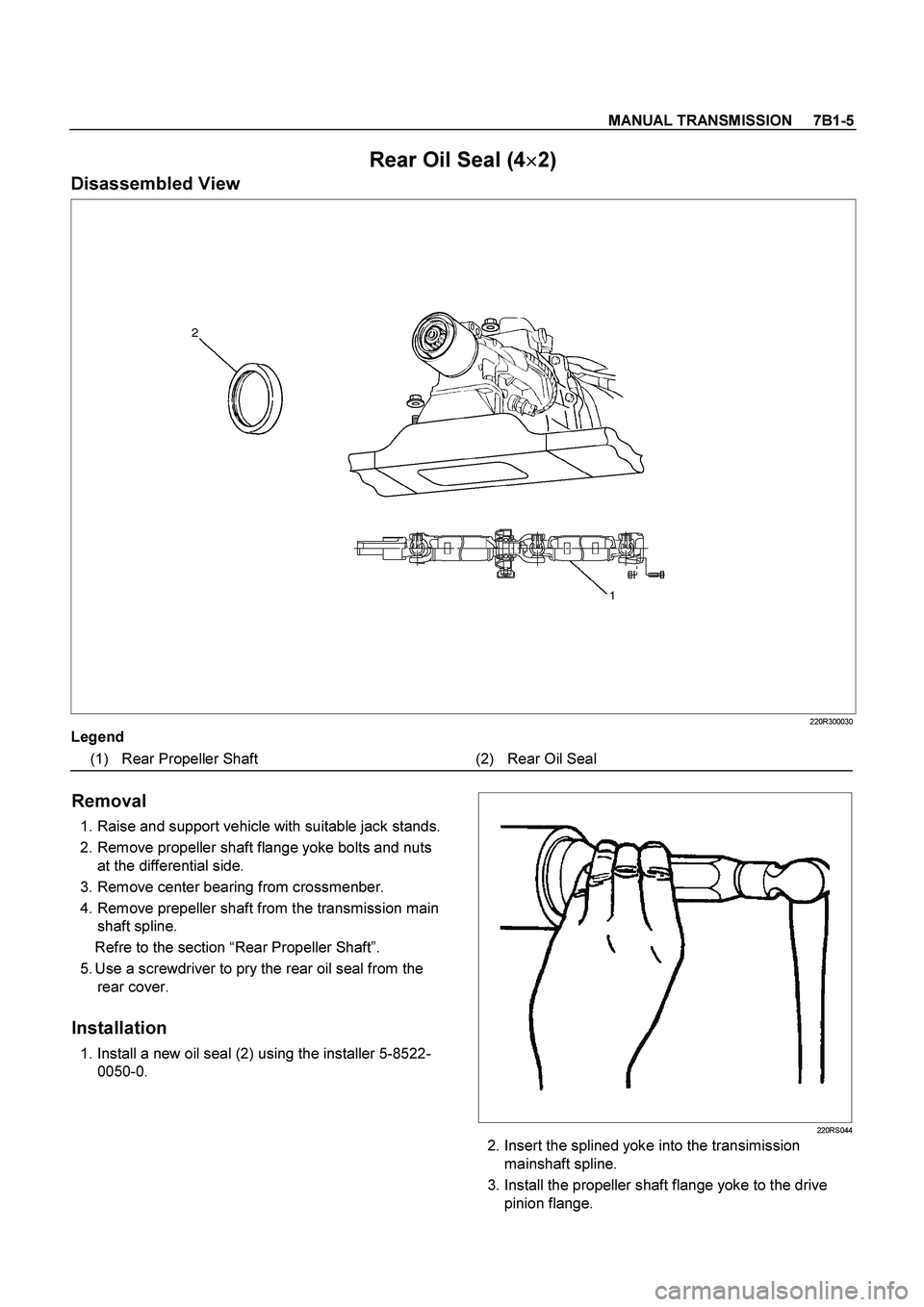
MANUAL TRANSMISSION 7B1-5
Rear Oil Seal (4�
�� �
2)
Disassembled View
220R300030
Legend
(1) Rear Propeller Shaft (2) Rear Oil Seal
Removal
1. Raise and support vehicle with suitable jack stands.
2. Remove propeller shaft flange yoke bolts and nuts
at the differential side.
3. Remove center bearing from crossmenber.
4. Remove prepeller shaft from the transmission main
shaft spline.
Refre to the section “Rear Propeller Shaft”.
5. Use a screwdriver to pry the rear oil seal from the
rear cover.
Installation
1. Install a new oil seal (2) using the installer 5-8522-
0050-0.
220RS044
2. Insert the splined yoke into the transimission
mainshaft spline.
3. Install the propeller shaft flange yoke to the drive
pinion flange.
Page 3172 of 4264
7B1-8 MANUAL TRANSMISSION
Removal
1. Disconnect battery ground cable.
2. Remove gear control lever knob (1).
3. Remove rear floor console (2). (Bucket seat)
Refer to the section “Floor Console”.
4. Remove front floor console (3).
Refer to the section “Floor Console”.
745R300006
Legend
(1) Knob
(2) Rear Floor Console
(3) Front Floor Console
5. Remove grommet assembly (4).
RTW47BMH000101

SECTION 7B")

SECTION 7B1")
.
3. Remove rear floor console (2). (Bucket seat)
Refer to the section “Flo")