Page 2485 of 4264
ENGINE MECHANICAL (C24SE) 6A-65
ENGINE EXTERNAL PARTS
Radiator
Removal
1. Disconnect battery ground cable.
2. Loosen a drain plug to drain EC.
3. Disconnect radiator inlet hose and outlet hose from the engine.
RTW46BSH000101
4. Remove fan guide(1), clips(2) on both sides and the
bottom lock, then remove lower fan guide(3) with fan
shroud(4).
5. Disconnect the reserve tank hose(6) from radiator.
RTW36BMH000101
6. Remove bracket(5).
7. Lift up and remove the radiator assembly with hose,
taking care not to damage the radiator core with a fan
blade.
Page 2486 of 4264
6A-66 ENGINE MECHANICAL (C24SE)
Installation
Follow the removal procedure in the reverse order to install the
radiator.
Thermostat
Removal
1. Remove water outlet nozzles with thermostat from
thermostat housing.
2. Remove coolant hose and collect coolant.
Important!
Remove and Install thermostat only together with water outlet
nozzles.
Tighten (Torque)
Water outlet nozzles to thermostat housing - 8 N�
m (0.8 kgf�
m)
Installation
1. Install coolant hose.
2. Fill cooling system and bleed according to the
corresponding operation.
Water Pump
Removal
1. Remove lower hose band from pipe band and collect
coolant.
2. Remove front toothed belt cover according to the
corresponding operation.
3. Remove water pump from cylinder block after releasing
tension on toothed belt.
Clean
Sealing surfaces
Page 2487 of 4264
 6A-67
Coating sealing surfaces with Silicone Grease
Installation
1. Install water pump to cylinder block with new rubber O-
ring.
2. Apply tension to toothed be")
ENGINE MECHANICAL (C24SE) 6A-67
Coating sealing surfaces with Silicone Grease
Installation
1. Install water pump to cylinder block with new rubber O-
ring.
2. Apply tension to toothed belt according to the
corresponding operation.
3. Install coolant hoses.
4. Fill cooling system and bleed according to the
corresponding operation.
Alternator
Removal
1. Remove ground cable from battery.
2. Remove cable connection from alternator and V-belt.
3. Remove alternator from retaining strap and lower
fastening.
Installation
1. Install alternator by tightening firmly by hand.
2. Install V-belt and apply tension according to the
corresponding operation.
3. Install cable connections to alternator.
4. Install ground cable to battery.
Starter
Removeal
1. Remove cable connections from starter.
2. Remove upper bolt of transmission side.
3. Remove lower bolt of engine side.
Tighten (Torque)
Starter to cylinder block:
Engine side - 51 N�
m (5.2 kgf�
m)
Transmission side - 75 N�
m (7.6 kgf�
m)
Starter support to cylinder block - 25 N�
m (2.5 kgf�
m)
Re-connect cables.
Page 2501 of 4264
 6A-81
Crankshaft, Cylinder Block
Cylinder Grinding and Piston Dimensions
Size Cylinder bore dia. in mm Cylinder to Related piston dia. in mm Piston head
Cranksh")
ENGINE MECHANICAL (C24SE) 6A-81
Crankshaft, Cylinder Block
Cylinder Grinding and Piston Dimensions
Size Cylinder bore dia. in mm Cylinder to Related piston dia. in mm Piston head
Crankshaft co- efficient
housing
co-efficient
over to over to
Production
(2.4L) 1 87.48
87.49 87.49
87.50 99
00 87.46
87.47 87.47
87.48 99
00
Customer
service
(2.4L) - 87.99 88.00 0+0.5 87.97 87.98 7+0.5
Piston diameter must be measured at the position "D".
*inclusive
Cylinder Bore
Rebore cylinder Permissible oversize to 0.5mm (see parts
microfiche)
After reboring, invalidate original crankcase
housing coefficient and drive in new oversize
coefficient
Permissible out-of-round: 0.013mm
Permissible taper: 0.013mm
Measure out-of-round in bore at 4 different
heights
Piston projection above upper edge of cylinder block
0.40mm
Piston
Type Recessed pistons
Clearance For short-blocks and cylinder blocks with
complete pistons, the clearance is 0.02 to
0.04mm
For replacement (oversize), depending on
available pistons, a clearance of 0.02 to
0.04mm is permissible
Page 2502 of 4264
6A-82 ENGINE MECHANICAL (C24SE)
Crankshaft, Cylinder Block (continued)
Piston Rings
2.4L
Square ring Height mm 1.2
Tapered ring Height mm 1.5
Oil scraper Height mm 2.5
Ring gap offset 180�
Note that the upper steel band ring gap is offset 25 to 50mm to
the left and the lower 25 to 50mm to the right opposite the
intermediate ring gap.
Piston Pin
Length mm 61.5
Diameter mm 21
Type Shrunk into con-rod
Play mm 2.4L
in piston 0.010-0.015
in con-rod none
Installation When installing piston pins,
heat con-rods to approx.
280�C in oil bath. This
temperature should under no
circumstances be exceeded.
Crankshaft, Cylinder Block (continued)
The permissible weight variation of con-rods without piston and
bearing shell inside an engine is 8 g.
As the con-rods do not have balancing studs, reworking is not
possible.
Con-rods can only be replaced in sets.
Page 2503 of 4264
 6A-83
Crankshaft, Cylinder Block (continued)
Crankshaft
jounal
I, II, IV, V Guide
bearing
III Con-rod journal
1 to 4 Con-rod width
Diameter
mm Widtht
mm Diame")
ENGINE MECHANICAL (C24SE) 6A-83
Crankshaft, Cylinder Block (continued)
Crankshaft
jounal
I, II, IV, V Guide
bearing
III Con-rod journal
1 to 4 Con-rod width
Diameter
mm Widtht
mm Diameter
mm Width
mm
mm
Normal size
Bearing journal and colour code from 57.9820 green
to 57.9885
> 57.9885 brown
to 57.9950
25.900
25.850
48.988
48.970
26.580
26.460
26.390
26.338
Bearing shell identification mark
Colour code and embossed Crankshaft bearing
I, II, IV, V Guide bearing
III Con-rod bearing
1 to 4
Identification mark brown-662N
green-663N brown-655N
green-658N
Crankshaft
jounal
I, II, IV, V Guide
bearing
III Con-rod journal
1 to 4 Con-rod width
Diameter
mm Widtht
mm Diameter
mm Width
mm
mm
0.25mm Undersize for Production and Customer Service
Bearing journal and colour code from 57.7320 green/
to 57.7385 blue
> 57.7385 brown/
to 57.7450 blue
26.100
26.050
48.738
48.720
26.580
26.460
Bearing shell identification mark
Colour code and embossed Crankshaft bearing
I, II, IV, V Guide bearing
III Con-rod bearing
1 to 4
Identification mark brown/blue-664 A
green/blue-655 A brown/blue-657 A
green/blue-658 A
Crankshaft
jounal
I, II, IV, V Guide
bearing
III Con-rod journal
1 to 4 Con-rod width
Diameter
mm Widtht
mm Diameter
mm Width
mm
mm
0.50mm Undersize Customer Service
Bearing journal and colour code from 57.4820 green/
to 57.4885 blue
> 57.4885 brown/
to 57.4950 blue
26.300
26.250
48.488
48.470
26.580
26.460
Bearing shell identification mark
Colour code and embossed Crankshaft bearing
I, II, IV, V Guide bearing
III Con-rod bearing
1 to 4
Identification mark brown/white-666 B
green/white-667 B brown/blue-659 B
green/blue-660 B
Page 2505 of 4264
 6A-85
Con-rod
Permissible, weight variation of con-rods without pistons and bearing shells within an engine 8 g.
As the con-rods have no counterweights, re-working is")
ENGINE MECHANICAL (C24SE) 6A-85
Con-rod
Permissible, weight variation of con-rods without pistons and bearing shells within an engine 8 g.
As the con-rods have no counterweights, re-working is not possible.
Con-rods must be replaced only as a set.
Crankshaft Grinding Dimensions
Crankshaft
bearing journals
I, II, III, IV, V
Guide bearings
III
Con-Rod bearing journals
1 to 4
Con-rod
diameter in
mm/colour code width
in mm diameter
in mm width
in mm width
in mm
Standard Size for Production and Service
from 57.974
white
to 57.981
over 57.981
green
to 57.988
over 57.988
brown
to 57.995 26.002
25.950
48.988
48.970
26.580
26.450
26.390
26.338
Crankshaft, Cylinder Block (continued)
Crankshaft and con-rod journal Permissible out-of-round:
0.04mm
Out-of-round Permissible variation of
middle crankshaft bearing
journal when seating shaft into
cylinder block: 0.03mm
Permissible end play 0.05 to 0.152mm
Permissible main bearing play Bearing I to V0.015 to
0.04mm
Permissible con-rod play 0.006 to 0.031mm
Permissible con-rod and play 0.07 to 0.24mm
Page 2506 of 4264
6A-86 ENGINE MECHANICAL (C24SE)
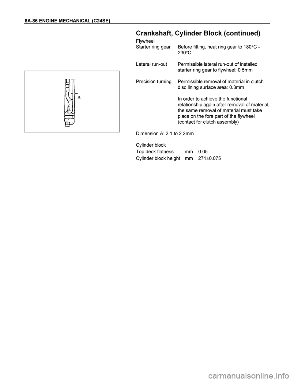
Crankshaft, Cylinder Block (continued)
Flywheel
Starter ring gear Before fitting, heat ring gear to 180�C -
230�C
Lateral run-out Permissible lateral run-out of installed
starter ring gear to flywheel: 0.5mm
Precision turning Permissible removal of material in clutch
disc lining surface area: 0.3mm
In order to achieve the functional
relationship again after removal of material,
the same removal of material must take
place on the fore part of the flywheel
(contact for clutch assembly)
Dimension A: 2.1 to 2.2mm
Cylinder block
Top deck flatness mm 0.05
Cylinder block height mm 271�0.075
 6A-65
ENGINE EXTERNAL PARTS
Radiator
Removal
1. Disconnect battery ground cable.
2. Loosen a drain plug to drain EC.
3. Disconnect radiator inlet hose a")

Installation
Follow the removal procedure in the reverse order to install the
radiator.
Thermostat
Removal
1. Remove water outlet nozzles with therm")

Crankshaft, Cylinder Block (continued)
Piston Rings
2.4L
Square ring Height mm 1.2
Tapered ring Height mm 1.5
Oil scraper Height mm 2.5
Ring")