Page 167 of 4264
REAR AXLE 4B-3
MAIN DATA AND SPECIFICATIONS
REAR AXLE
Ring gear size mm(in)220 (8.66)
Rear axle type Banjo, semi-floating
Rear axle capacity N (kg/lb)16475 (1680/3700)
Rear axle case 16965 (1730/3815) (EC)
Axle tube section
Outside diameter mm(in)80 (3.15)
Thickness mm(in)4.5 (0.118)
Final drive type Single speed
Final gear type Hypoid
Drive pinion bearing preload kg-cm(lb.in)
Starting torque (At drive pinion flange nut) 7-13 (6.1-11.3)
Preload adjusting method Collapsible
Final gear backlash mm(in)0.15-0.20 (0.006-0.008)
Differential carrier assembly
Weight (Dry) kg/lb29.0/63.9
Lubrication
Specified gear oil (APL grade) GL5 (STD), GL5LSD (LSD)
Oil capacity lit (US/UK gal)2.4 (0.63/0.53)
Page 173 of 4264
REAR AXLE 4B-9
REAR AXLE
1.
Refer to Section 3E "WHEEL and TIRE" for road
wheel Disassembly procedure.
2.
Refer to Section 5 "BRAKE" for rear brake
removal procedure.
RTW34BLF000401
Legend
1. Brake Drum
2. Bolt and Nut
3. Axle Shaft Assembly with Brake
4.
Shim
5. Snap Ring
6. Axle Shaft
7. Sensor Rotor (with ABS)
Spacer (without ABS)
8.
Double Taper Roller Bearing
9. Oil Seal
10.
Bearing Holder
11. Rear Brake
12. Bolt and Nut
13. Differential Assembly
14. Rear Axle Case Assembly
15. Wheel Pin
16. Axle Case Oil Seal
17.
Front
Page 174 of 4264
4B-10 REAR AXLE
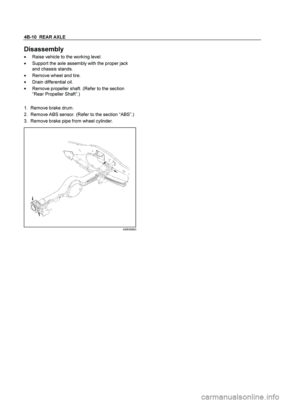
Disassembly
�
Raise vehicle to the working level.
�
Support the axle assembly with the proper jack
and chassis stands.
�
Remove wheel and tire.
�
Drain differential oil.
�
Remove propeller shaft. (Refer to the section
“Rear Propeller Shaft”.)
1.
Remove brake drum.
2. Remove ABS sensor. (Refer to the section “ABS”.)
3. Remove brake pipe from wheel cylinder.
420R300003
Page 182 of 4264
4B-18 REAR AXLE
17.
Install brake pipe and ABS sensor and tighten it to
the specified torque.
Torque :
ABS Sensor
8 N�
m (0.8 kg�
m/69 lb�
ft)
Brake Pipe
16 N�
m (1.6 kg�
m/12 lb�
ft)
420R30003
18.
Bleed brake pipe at the wheel cylinder. (Refer to
the section “Power-assisted Brake System”)
19.
Install brake drum.
�
Install propeller shaft. (Refer to Section “Rear
Propeller Shaft”.)
�
Refill differential oil.
�
Install wheel and tire.
�
Lower vehicle.
Page 199 of 4264
REAR AXLE 4B-35
Reassembly
1. Install side gear with thrust washer in differential
cage.
2. Install the pinion gear by engaging it with the side
gears while turning both pinion gears
simultaneously in the same direction.
425RS048
3. Install cross pin.
�
Be sure to install the cross pin so that it is in
alignment with the lock pin hole in the
differential cage.
425RS049
4. Check the amount of backlash.
Backlash between the side gear and the pinion
gear. mm (in)
0.13-0.18 (0.005-0.007)
If the backlash is beyond the limits, adjust with a thrust
washer of selected thickness.
Thicknesses of thrust washers available.
Backlash mm (in
)
0.80
(0.031)0.90
(0.035)1.00
(0.039) 1.10
(0.043) 1.20
(0.047)1.30
(0.051)
425RY00008
5. Install lock pin.
After lock pin installation, stake the case to
secure the lock pin.
6. Install ring gear.
Refer to “Ring gear replacement” on this section.
Page 207 of 4264
REAR AXLE 4B-43
TROUBLESHOOTING
Refer to this Section to quickly diagnose and repair
rear axle problems.
Each troubleshooting chart has three headings
arranged from left to right.
(1) Checkpoint
(2) Trouble Cause
(3) Countermeasure
This Section is divided into five sub-sections:
1. Abnormal Rear Axle Noise
1) Noise when the engine is driving the vehicle
2) Noise when the vehicle is coasting
3) Intermittent noise
4) Noise when the vehicle is turning
5) Constant noise
2. Vibration
3. Oil Leakage
1) Differential carrier leakage
2) Axle case leakage
3) Axle case to inside hub leakage
4) Axle case to inside brake drum leakage
4. Power Not Being Transmitted to the Wheels
(Propeller Shaft Operation is Normal)
Page 221 of 4264

FRONT WHEEL DRIVE 4C1-1
SECTION 4C1
FRONT WHEEL DRIVE
TABLE OF CONTENTS
PAGE
Main Data and Specifications ........................................................................................... 4C1- 3
Special Parts Fixing Nuts and Bolts ................................................................................ 4C1- 4
Recommended Liquid Gasket .......................................................................................... 4C1- 6
Recommended Thread Locking Agents .......................................................................... 4C1- 6
Servicing............................................................................................................................. 4C1- 7
General Description........................................................................................................... 4C1- 8
Front Drive Axle Assembly ............................................................................................. 4C1- 14
Front Drive Axle Assembly and Associated Parts ................................................... 4C1- 14
Removal ....................................................................................................................... 4C1- 15
Installation ...................................................................................................................4C1- 16
Front Axle Drive Shaft ..................................................................................................... 4C1- 18
Front Axle Drive Shaft and Associated Parts ........................................................... 4C1- 18
Disassembly ................................................................................................................ 4C1- 19
Inspection and Repair................................................................................................. 4C1- 20
Bushing Replacement ............................................................................................... 4C1- 21
Reassembly ................................................................................................................. 4C1- 21
Standard caulk Measure ............................................................................................ 4C1- 22
Differential ...................................................................................................................4C1- 24
Disassembly ................................................................................................................ 4C1- 24
Major Components ................................................................................................ 4C1- 24
Minor Components................................................................................................ 4C1- 27
Inspection and Repair................................................................................................. 4C1- 29
Reassembly ................................................................................................................ 4C1- 31
Minor Components ................................................................................................. 4C1- 31
Major Components ................................................................................................. 4C1- 33
Page 235 of 4264

FRONT WHEEL DRIVE 4C1-15
Removal
1. Jack up the vehicle and support it using jack stand.
2. Remove the tire and wheel.
3. Remove the stone guard.
4. Remove the brake caliper fixing bolt and hang the caliper.
Refer to Disc Brakes in Brake section.
5. Remove the antilock brake system speed sensor.
Refer to Front Wheel Speed Sensor in Brake section.
6. Remove the hub and disc assembly.
Refer to Front Hub and Disc in this section.
7. Remove the propeller shaft, refer to Front Propeller Shaft in
this section.
8. Loosen the height control arm of the torsion bar, then
remove the torsion bar from lower control arm.
Refer to Torsion Bar in Suspension section.
9. Remove the suspension crossmember.
10. Remove the lower nut (1) of the stabilizer link.
11. Remove the lower bolt and nut (2) of the shock absorber.
12. Remove the tie-rod end from the knuckle.
Refer to Power Steering Unit in Steering Section.
13. Disconnect the breather hose of the front axle.
14. Disconnect the actuator connector. (With shift on the fly)
15. Remove the bolts and nuts of the lower control arm (Frame
side), then disconnect the lower control arm from frame.
16. Disconnect between the right side upper control arm and
the knuckle, then remove the knuckle with lower control
arm.
CAUTION :
When removing the knuckle, be careful not to damage the
oil seal inside of the knuckle.
220 (8.66)
Rear axle type Banjo, semi-floating
Rear axle capacity N (kg/lb)16475 (1680/3700)
Rear axle case 16965")


 Checkpoi")