2004 ISUZU TF SERIES section 8
[x] Cancel search: section 8Page 77 of 4264

RESTRAINT CONTROL 9A1-7
System Schematic
RTW49JLF000101
SRS Diagnostic System Check
The diagnostic procedures used in this section are
designed to find and repair SRS malfunctions. To get
the best results, it is important to use the diagnostic
charts and follow the sequence listed below:
A
Perform the “SRS Diagnostic System Check.”
The “SRS Diagnostic System Check” must be the
starting point of any SRS diagnostics. The “SRS
Diagnostic System Check” checks for proper “AIR
BAG” warning lamp operation, the ability of the SRS
control unit to communicate through the “Serial
Data” line and whether SRS diagnostic trouble codes
exist.
B
Refer to the proper diagnostic chart as directed by
the “SRS Diagnostic System Check.”
The “SRS Diagnostic System Check” will lead you to
the correct chart to diagnose any SRS malfunctions.
Bypassing these procedures may result in extended
diagnostic time, incorrect diagnosis and incorrect
parts replacement.
C
Repeat the “SRS Diagnostic System Check” after
any repair or diagnostic procedures have been
preformed.
Performing the “SRS Diagnostic System Check”
after all repair or diagnostic procedures will ensure
that the repair has been made correctly and that no
other malfunctions exist
Page 78 of 4264

9A1-8 RESTRAINT CONTROL SYSTEM
Circuit Description
When the ignition switch is first turned “ON”, “Ignition 1”
voltage is applied from the “SRS” fuse to the SRS
control unit at the “Ignition 1” input terminals “35”. The
SRS control unit responds by flashing the “AIR BAG”
warning lamp seven times, while performing tests on
the SRS.
Notes On System Check Chart
1.
The “AIR BAG” warning lamp should flash seven
times after ignition is first turned “ON”.
2.
After the “AIR BAG” warning lamp flashes seven
times, it should turn “OFF”
3.
This test checks for the proper operation of the
“Serial Data” line. This test will also determine
whether history diagnostic trouble codes are stored
and, if so, identify them.
4.
Improper operation of the “AIR BAG” warning lamp
is indicated. This test differentiates a warning lamp
stays “ON” condition from a warning lamp does not
come “ON” condition.
5.
This test checks for proper operation of the “Serial
Data” line. This test will also identify the stored
diagnostic trouble codes and whether they are
current or history.
Diagnostic Aids
The order in which diagnostic trouble codes are
diagnosed is very important. Failure to diagnose the
diagnostic trouble codes in the order specified may
result in extended diagnostic time, incorrect diagnosis
and incorrect parts replacement.
SRS Diagnostic System Check
Step Action Yes No
1 Note the “Air Bag” warning lamp as ignition switch is turned “ON.”
Does the “AIR BAG” warning lamp flash seven 7 times? Go to Step 2 Go to Step 3
2 Note the “AIR BAG” warning lamp after it flashed 7 times.
Does the “AIR BAG” warning lamp go “OFF”? Go to Step 4 Go to Step 5
3 Note the “AIR BAG” warning lamp as ignition switch is turned
“ON”.
Does the “AIR BAG” warning lamp come “ON” steady? Go to Chart B. Go to Chart C.
4
1.
Note the “AIR BAG” warning lamp as that ignition switch is
turned “ON.”
Ignition switch “OFF.”
2.
Connect a scan tool to data link connector.
3.
Follow direction given in the scan tool instruction manual.
Ignition switch “ON.”
4.
Request the SRS diagnostic trouble code display, recode all
history diagnostic trouble code(s). specify as such, on repair
order
Is (are) diagnostic trouble code(s) displayed? Ignition switch
“OFF.”
When DTC B1000 is
set, go to DTC
B1000 Chart.
For all other history
codes refer to
“Diagnostic Aids”
For that specific
DTC.
A history DTC
indicates the
malfunction has
been repaired or is
intermittent. SRS is functional
and free of
malfuncitons, no
further diagnosis is
required.
If scan tool indicated
“NO DATA
RECEIVED,” refer to
chassis electrical
section 8.
Page 79 of 4264

RESTRAINT CONTROL 9A1-9
Step Action Yes No
5
1. Ignition switch “OFF.”
2. Connect a scan tool to data link connector.
3. Follow directions as given in the scan tool instruction
manual.
4. Ignition switch “ON.”
5. Request the SRS diagnostic trouble code display, Recode
all diagnostic trouble code(s), specifying as current or history
on repair order.
Is (are) diagnostic trouble code (s) displayed? Ignition switch
“OFF”.
When DTC B0053 is
set, go to DTC
B0053 chart.
When DTC B0051 is
set, go to DTC
B0051 chart.
When DTC B0018
is set, go to DTC
B0018 chart.
When DTC B0024
is set, go to DTC
B0024 chart.
Diagnose remaining
current DTCs from
lowest to highest.
When only history
DTCs exist, refer to
“Diagnostics Aids”
for that specific
DTC.
A history DTC
indicates the
malfunction has
been repaired or is
intermittent. If scan tool indicates
“No Data Received,”
refer to chassis
electrical section 8.
Page 108 of 4264

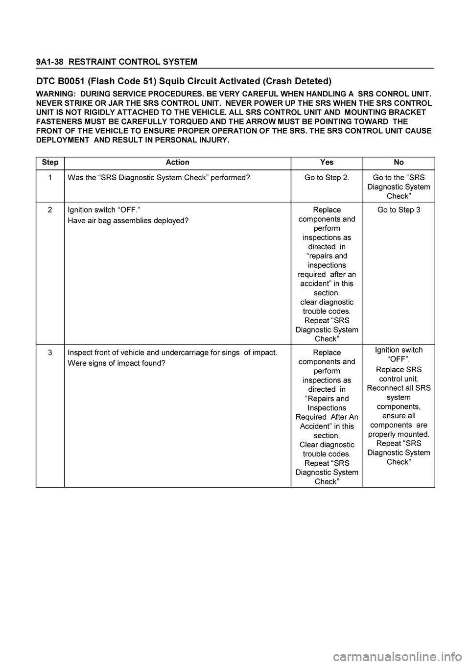
9A1-38 RESTRAINT CONTROL SYSTEM
DTC B0051 (Flash Code 51) Squib Circuit Activated (Crash Deteted)
WARNING: DURING SERVICE PROCEDURES. BE VERY CAREFUL WHEN HANDLING A SRS CONROL UNIT.
NEVER STRIKE OR JAR THE SRS CONTROL UNIT. NEVER POWER UP THE SRS WHEN THE SRS CONTROL
UNIT IS NOT RIGIDLY ATTACHED TO THE VEHICLE. ALL SRS CONTROL UNIT AND MOUNTING BRACKET
FASTENERS MUST BE CAREFULLY TORQUED AND THE ARROW MUST BE POINTING TOWARD THE
FRONT OF THE VEHICLE TO ENSURE PROPER OPERATION OF THE SRS. THE SRS CONTROL UNIT CAUSE
DEPLOYMENT AND RESULT IN PERSONAL INJURY.
Step Action Yes No
1 Was the “SRS Diagnostic System Check” performed? Go to Step 2. Go to the “SRS
Diagnostic System
Check”
2 Ignition switch “OFF.”
Have air bag assemblies deployed? Replace
components and
perform
inspections as
directed in
“repairs and
inspections
required after an
accident” in this
section.
clear diagnostic
trouble codes.
Repeat “SRS
Diagnostic System
Check” Go to Step 3
3 Inspect front of vehicle and undercarriage for sings of impact.
Were signs of impact found? Replace
components and
perform
inspections as
directed in
“Repairs and
Inspections
Required After An
Accident” in this
section.
Clear diagnostic
trouble codes.
Repeat “SRS
Diagnostic System
Check” Ignition switch
“OFF”.
Replace SRS
control unit.
Reconnect all SRS
system
components,
ensure all
components are
properly mounted.
Repeat “SRS
Diagnostic System
Check”
Page 110 of 4264

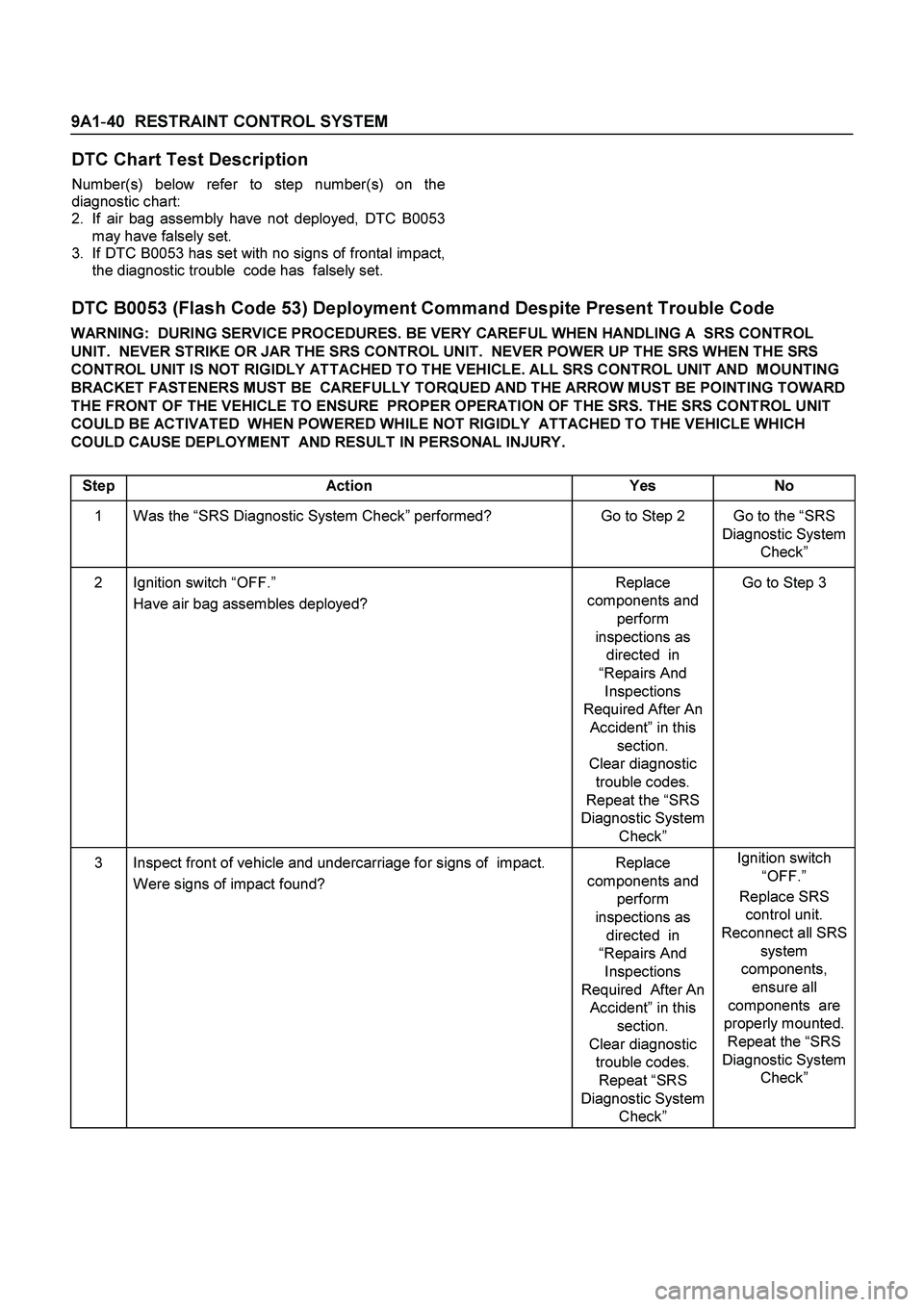
9A1-40 RESTRAINT CONTROL SYSTEM
DTC Chart Test Description
Number(s) below refer to step number(s) on the
diagnostic chart:
2.
If air bag assembly have not deployed, DTC B0053
may have falsely set.
3.
If DTC B0053 has set with no signs of frontal impact,
the diagnostic trouble code has falsely set.
DTC B0053 (Flash Code 53) Deployment Command Despite Present Trouble Code
WARNING: DURING SERVICE PROCEDURES. BE VERY CAREFUL WHEN HANDLING A SRS CONTROL
UNIT. NEVER STRIKE OR JAR THE SRS CONTROL UNIT. NEVER POWER UP THE SRS WHEN THE SRS
CONTROL UNIT IS NOT RIGIDLY ATTACHED TO THE VEHICLE. ALL SRS CONTROL UNIT AND MOUNTING
BRACKET FASTENERS MUST BE CAREFULLY TORQUED AND THE ARROW MUST BE POINTING TOWARD
THE FRONT OF THE VEHICLE TO ENSURE PROPER OPERATION OF THE SRS. THE SRS CONTROL UNIT
COULD BE ACTIVATED WHEN POWERED WHILE NOT RIGIDLY ATTACHED TO THE VEHICLE WHICH
COULD CAUSE DEPLOYMENT AND RESULT IN PERSONAL INJURY.
Step Action Yes No
1 Was the “SRS Diagnostic System Check” performed? Go to Step 2 Go to the “SRS
Diagnostic System
Check”
2 Ignition switch “OFF.”
Have air bag assembles deployed? Replace
components and
perform
inspections as
directed in
“Repairs And
Inspections
Required After An
Accident” in this
section.
Clear diagnostic
trouble codes.
Repeat the “SRS
Diagnostic System
Check” Go to Step 3
3 Inspect front of vehicle and undercarriage for signs of impact.
Were signs of impact found? Replace
components and
perform
inspections as
directed in
“Repairs And
Inspections
Required After An
Accident” in this
section.
Clear diagnostic
trouble codes.
Repeat “SRS
Diagnostic System
Check” Ignition switch
“OFF.”
Replace SRS
control unit.
Reconnect all SRS
system
components,
ensure all
components are
properly mounted.
Repeat the “SRS
Diagnostic System
Check”
Page 135 of 4264

WORKSHOP MANUAL
TF SERIES
AXLE
SECTION 4
Page 137 of 4264

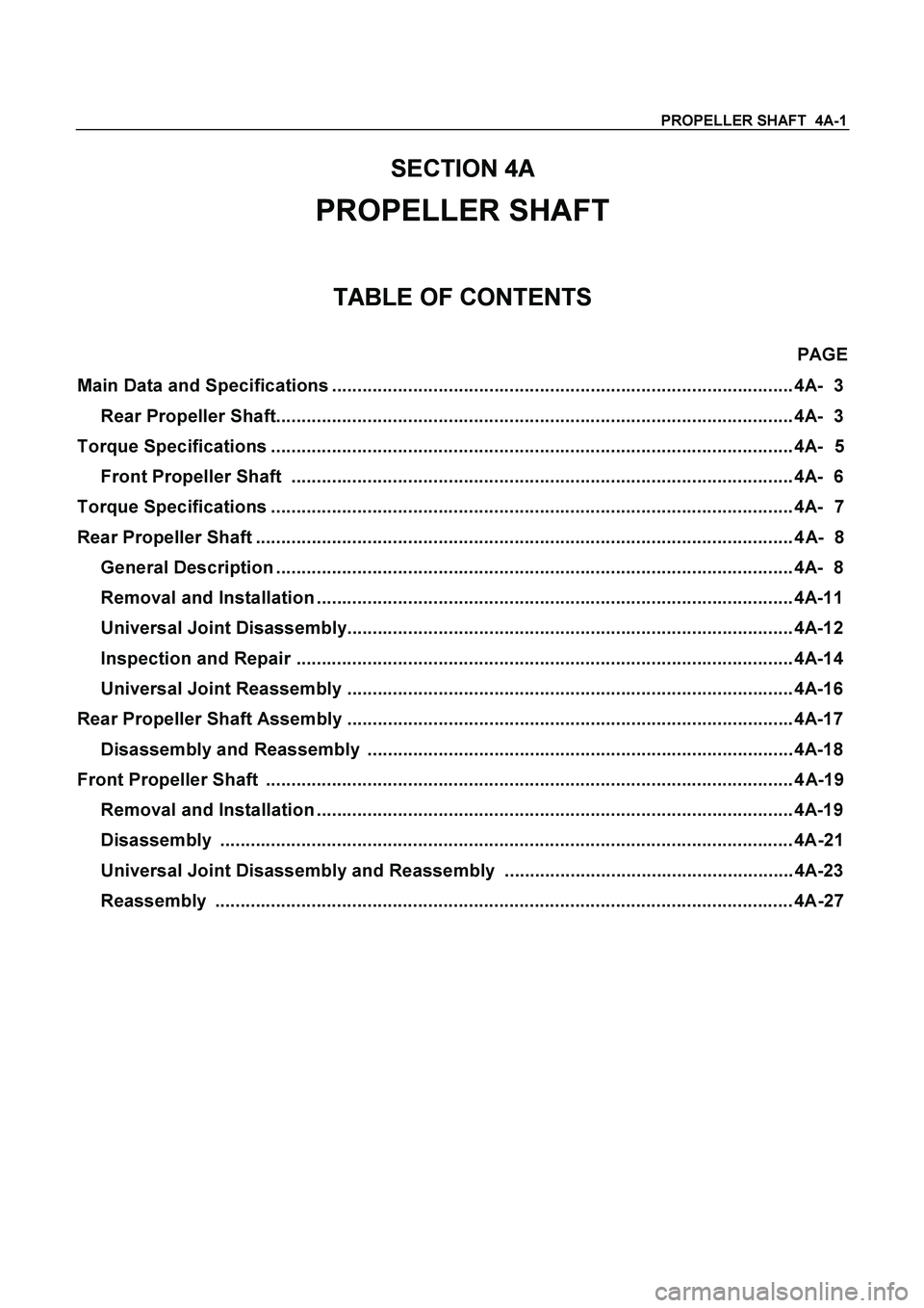
PROPELLER SHAFT 4A-1
SECTION 4A
PROPELLER SHAFT
TABLE OF CONTENTS
PAGE
Main Data and Specifications ........................................................................................... 4A- 3
Rear Propeller Shaft...................................................................................................... 4A- 3
Torque Specifications ....................................................................................................... 4A- 5
Front Propeller Shaft ................................................................................................... 4A- 6
Torque Specifications ....................................................................................................... 4A- 7
Rear Propeller Shaft .......................................................................................................... 4A- 8
General Description ...................................................................................................... 4A- 8
Removal and Installation .............................................................................................. 4A-11
Universal Joint Disassembly........................................................................................ 4A-12
Inspection and Repair .................................................................................................. 4A-14
Universal Joint Reassembly ........................................................................................ 4A-16
Rear Propeller Shaft Assembly ........................................................................................ 4A-17
Disassembly and Reassembly .................................................................................... 4A-18
Front Propeller Shaft ........................................................................................................ 4A-19
Removal and Installation .............................................................................................. 4A-19
Disassembly ................................................................................................................. 4A-21
Universal Joint Disassembly and Reassembly ......................................................... 4A-23
Reassembly .................................................................................................................. 4A-27
Page 165 of 4264

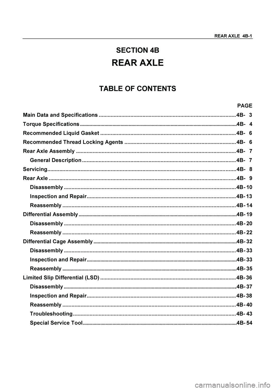
REAR AXLE 4B-1
SECTION 4B
REAR AXLE
TABLE OF CONTENTS
PAGE
Main Data and Specifications ........................................................................................... 4B- 3
Torque Specifications....................................................................................................................4B- 4
Recommended Liquid Gasket .......................................................................................... 4B- 6
Recommended Thread Locking Agents .......................................................................... 4B- 6
Rear Axle Assembly .......................................................................................................... 4B- 7
General Description ...................................................................................................... 4B- 7
Servicing............................................................................................................................. 4B- 8
Rear Axle ............................................................................................................................ 4B- 9
Disassembly .................................................................................................................. 4B- 10
Inspection and Repair................................................................................................... 4B- 13
Reassembly ................................................................................................................... 4B- 14
Differential Assembly.....................................................................................................................4B- 19
Disassembly .................................................................................................................. 4B- 20
Reassembly ................................................................................................................... 4B- 22
Differential Cage Assembly..........................................................................................................4B- 32
Disassembly .................................................................................................................. 4B- 33
Inspection and Repair...............................................................................................................4B- 33
Reassembly.................................................................................................................................4B- 35
Limited Slip Differential (LSD) .......................................................................................... 4B- 36
Disassembly................................................................................................................................4B- 37
Inspection and Repair................................................................................................... 4B- 38
Reassembly ................................................................................................................... 4B- 40
Troubleshooting ............................................................................................................ 4B- 43
Special Service Tool..................................................................................................................4B- 54