Page 835 of 4264

ELECTRICAL-BODY AND CHASSIS 8A-177
REAR COMBINATION LIGHT
Back Up Light
Removal
1. Open the rear gate.
2. Remove the screws.
3. Remove the rear combination light assembly.
4. Turn the bulb
3 counterclockwise to remove it.
Installation
Follow the removal procedure in the reverse order to install the
rear combination light.
Pay close attention to the important points mentioned in the
following paragraphs.
Bulbs
Be absolutely sure that each bulb is correctly installed.
This will prevent a poor contact and an open circuit.
This illustration is based on RHD model
HAZARD WARNING FLASHER SWITCH
Removal
1. Disconnect the battery ground cable.
2. Instrument Panel Cluster Assembly
� Refer to Section 10 “BODY” for instrument panel cluste
r
assembly removal steps.
3. Hazard Warning Switch
� Disconnect the switch connector.
� To remove the switch, push the lock from the back side
of the cluster assembly.
Installation
To install, follow the removal procedure in the reverse order.
Connector
Be absolutely sure that the hazard warning flasher switch
connector is securely connected.
This will prevent a poor contact and an open circuit.
Page 836 of 4264

8A-178 ELECTRICAL-BODY AND CHASSIS
BACK UP LIGHT SWITCH
Removal
1. Disconnect the battery ground cable.
2. Disconnect the connector
1.
3. Remove the back up light switch from the transmission
2.
Installation
Follow the removal procedure in the reverse order to install the
back up light switch.
Pay close attention to the important points mentioned in the
following paragraphs.
Back up Light Switch Threads
Apply liquid gasket to the threaded portion and install the back
up light switch.
Connector
Be absolutely sure that the back up light connector is securely
connected.
This will prevent a poor contact and an open circuit.
HORN
Removal
1. Remove the radiator grille.
Refer to the “HEADLIGHT” removal procedure.
2. Loosen the horn bolt.
3. Disconnect the horn connector.
Installation
Follow the removal procedure in the reverse order to install the
horn.
Pay close attention to the important point mentioned in the
following paragraphs.
Connector
Be absolutely sure the horn connector is securely connected.
This will prevent a poor contact and open circuit.
Page 851 of 4264
ELECTRICAL-BODY AND CHASSIS 8A-193
DOOR SWITCH
Removal
1. Disconnect the battery ground cable.
2. Loosen the screw
1.
3. Remove the door switch.
4. Disconnect the door switch connector
3.
Installation
Follow the removal procedure in the reverse order to install the
spot light.
Pay close attention to the important points mentioned in the
following paragraphs.
Connector
Be absolutely sure that the door switch connector is securely
connected.
This will prevent a poor contact and an open circuit.
SPOT LIGHT (MAP Light)
Removal
1. Grasp the spot light housing
1 with both hands.
Pull the housing straight down.
This will release the clip.
2. Disconnect the connector
2.
3. Turn socket
3 counterclockwise to remove it.
Page 852 of 4264

8A-194 ELECTRICAL-BODY AND CHASSIS
Installation
Follow the removal procedure in the reverse order to install the
spot light.
Pay close attention to the important points mentioned in the
following paragraphs.
Connector
Be absolutely sure that the spot light connector is securely
connected.
This will prevent a poor contact and an open circuit.
Bulb
Be absolutely sure that the spot light bulb is correctly installed.
This will prevent a poor contact and an open circuit.
RTW48ASH000801
WARNING BUZZER (ALARMER
CONTROL UNIT)
Removal
1. Disconnect the battery ground cable.
2. Remove the glove box
� Remove the screw.
3. Remove the Alarmer C/U assembly
� Remove the screw.
Installation
Follow the removal procedure in the reverse order to install the
warning buzzer.
Pay close attention to the important points mentioned in the
following paragraphs.
Connector
Be absolutely sure that the warning buzzer connector is
securely connected.
This will prevent a poor contact and an open circuit.
Page 865 of 4264
ELECTRICAL-BODY AND CHASSIS 8A-207
REMOVAL AND INSTALLATION
WIPER AND WASHER SWITCH
Removal
Refer to the removal steps of the LIGHTING SWITCH
(COMBINATION SWITCH) in “ LIGHTING “ of this section.
Installation
Follow the removal procedure in the reverse order to install the
wiper and washer switch.
This illustration is based on RHD model
Pay close attention to the important points mentioned in the
following paragraphs.
Connector
Be absolutely sure that the wiper and washer switch connector
is securely connected.
This will prevent a poor contact and an open circuit.
Page 870 of 4264
8A-212 ELECTRICAL-BODY AND CHASSIS
Windshield Washer Spray
Be sure that the engine hood is completely closed before
checking the windshield washer spray adjustment.
Windshield Washer Spray Position: Refer to the illustration.
RTW38DSF000201
Connector
Be absolutely sure that the wiper motor connector is securely
connected.
This will prevent a poor contact and an open circuit.
Note:
Windshield wiper arm and blade assembly configurations
are different for the right-hand and left-hand side of the
vehicle.
Be careful not to confuse the right-hand and left-hand side
assemblies.
This illustration is based on RHD model
WASHER TANK MOTOR
Removal
1. Remove the head light.
� Refer to the head light in this manual.
2. Remove the inner riner.
3. Pull out the clip washer filler.
4. Remove the washer tank nuts.
Page 871 of 4264
ELECTRICAL-BODY AND CHASSIS 8A-213
4. Disconnect the connector
1.
5. Disconnect the water hose
2.
6. Pull out the washer tank motor
3.
Installation
Follow the removal procedure in the reverse order to install the
washer tank motor.
Pay close attention to the important points mentioned in the
following paragraphs.
Connector
Be absolutely sure that the washer tank motor connector is
securely connected.
This will prevent a poor contact and an open circuit.
Page 920 of 4264
8A-262 ELECTRICAL-BODY AND CHASSIS
REMOVAL AND INSTALLATION
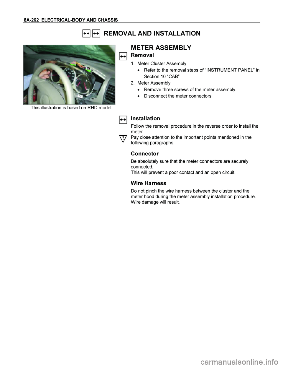
This illustration is based on RHD model
METER ASSEMBLY
Removal
1. Meter Cluster Assembly
� Refer to the removal steps of “INSTRUMENT PANEL” in
Section 10 “CAB”
2. Meter Assembly
� Remove three screws of the meter assembly.
� Disconnect the meter connectors.
Installation
Follow the removal procedure in the reverse order to install the
meter.
Pay close attention to the important points mentioned in the
following paragraphs.
Connector
Be absolutely sure that the meter connectors are securely
connected.
This will prevent a poor contact and an open circuit.
Wire Harness
Do not pinch the wire harness between the cluster and the
meter hood during the meter assembly installation procedure.
Wire damage will result.

 in “ LIGHTING “ of")