Page 1845 of 4264
 6A-21
Cylinder Head Cover LH
Removal
1. Disconnect battery ground cable.
2. Disconnect positive crankcase ventilation hose.
3. Remove camshaft angle sensor connecto")
ENGINE MECHANICAL (6VE1 3.5L) 6A-21
Cylinder Head Cover LH
Removal
1. Disconnect battery ground cable.
2. Disconnect positive crankcase ventilation hose.
3. Remove camshaft angle sensor connector.
4. Remove ground cable fixing bolt on cylinder head
cover.
5. Ignition coil connector and ignition coil.
� Disconnect the three connectors from the
ignition coils.
� Remove harness bracket bolt on cylinder head
cover.
� Remove fixing bolts on ignition coils.
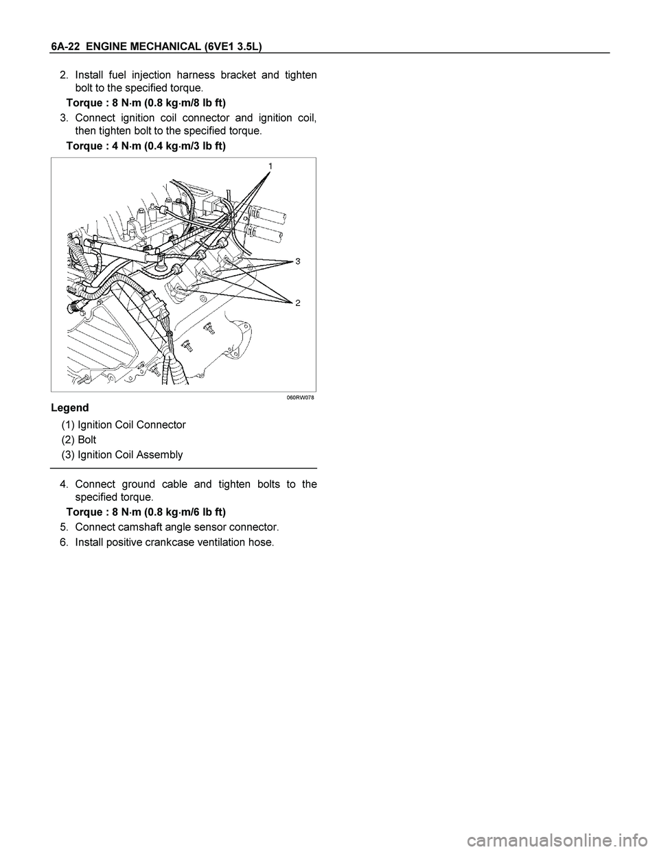
060RW078
Legend
(1) Ignition Coil Connector
(2) Bolt
(3) Ignition Coil Assemblies
6. Remove fixing bolt for fuel injector harness
bracket.
7. Remove eight fixing bolts, then the cylinder head
cover.
010RW001
Installation
1. Install cylinder head cover.
� Clean the sealing surface of cylinder head and
cylinder head cover to remove oil and sealing
materials completely.
� Apply sealant (TB-1207B or equivalent) of bead
diameter 2-3 mm at eight place of arched area
of camshaft bracket on front and rear sides.
� The cylinder head cover must be installed with
in 5 minutes after sealant application to preven
t
hardening of sealant.
� Tighten bolts to the specified torque.
Torque : 9 N�
�� �m (0.9 kg�
�� �m/7 lb ft)
010RW006
Page 1846 of 4264
6A-22 ENGINE MECHANICAL (6VE1 3.5L)
2. Install fuel injection harness bracket and tighten
bolt to the specified torque.
Torque : 8 N�
�� �m (0.8 kg�
�� �m/8 lb ft)
3. Connect ignition coil connector and ignition coil,
then tighten bolt to the specified torque.
Torque : 4 N�
�� �m (0.4 kg�
�� �m/3 lb ft)
060RW078
Legend
(1) Ignition Coil Connector
(2) Bolt
(3) Ignition Coil Assembly
4. Connect ground cable and tighten bolts to the
specified torque.
Torque : 8 N�
�� �m (0.8 kg�
�� �m/6 lb ft)
5. Connect camshaft angle sensor connector.
6. Install positive crankcase ventilation hose.
Page 1847 of 4264
 6A-23
Cylinder Head Cover RH
Removal
1. Disconnect battery ground cable.
2. Remove air cleaner duct assembly.
3. Disconnect ventilation hose from cylinder head
cove")
ENGINE MECHANICAL (6VE1 3.5L) 6A-23
Cylinder Head Cover RH
Removal
1. Disconnect battery ground cable.
2. Remove air cleaner duct assembly.
3. Disconnect ventilation hose from cylinder head
cover.
4. Disconnect three ignition coil connectors from
ignition coils and remove harness bracket bolts on
cylinder head cover then remove ignition coil fixing
bolts on ignition coils and remove ignition coils.
5. Remove heater pipe fixing bolts from the bracket.
6. Disconnect fuel injector harness connector then
remove fuel injector harness bracket bolt.
7. Remove eight fixing bolts then the cylinder head
cover.
010RW002
Installation
1. Install cylinder head cover.
� Clean the sealing surface of cylinder head and
cylinder head cover to remove oil and sealing
materials completely.
� Apply sealant (TB-1207B or equivalent) of bead
diameter 2‐3 mm at eight place of arched
area of camshaft bracket on front and rea
r
sides.
� The cylinder head cover must be installed
within 5 minutes after sealant application to
prevent premature hardening of sealant.
� Tighten bolts to the specified torque.
Torque : 9 N�
�� �m (0.9 kg�
�� �m/7 lb ft)
014RW019
2. Install exhaust gas recirculation pipe and tighten to
specified torque.
Torque :
Exhaust manifold side: 29 N�
�� �m (3.0 kg�
�� �m/21 lb ft)
Flare nut: 44 N�
�� �m (4.5 kg�
�� �m/33 lb ft)
Cylinder head side: 20 N�
�� �m (2.0 kg�
�� �m/14 lb ft)
3. Tighten fuel injector harness bracket bolts to
specified torque then reconnect fuel injecto
r
harness connector.
Torque : 8 N�
�� �m (0.8 kg�
�� �m/5.7 lb ft)
4. Install heater pipe bolt to the specified torque.
Torque : 20 N�
�� �m (2.0 kg�
�� �m/14 lb ft)
5. Connect ignition coil connector and tighten ignition
coil fixing bolts to specified torque.
Torque : 4 N�
�� �m (0.4 kg�
�� �m/3 lb ft)
6. Connect ventilation hose to cylinder head.
7. Install air cleaner duct assembly.
Page 1917 of 4264
ENGINE MECHANICAL (6VE1 3.5L) 6A-93
Main Data and Specification
General Specification
Item Specifications
Engine type, number of cylinders and arrangement Water cooled, four cycle V6
Form of combustion chamber Pent-roof type
Valve mechanism 4-Cams, 4-Valves, DOHC Gear & Belt Drive
Cylinder liner type Casted in cylinder block
Total piston displacement 3494 cc
Cylinder bore x stroke 93.4mm x 85.0mm
(3.6772 in � 3.3465 in)
Compression ratio 8.6
Compression pressure at 300rpm 1.37 MPa (14.0 Kg/cm2)
Engine idling speed rpm Non adjustable (750)
Valve clearance Intake: 0.28 mm (0.11 in)
Exhaust: 0.30mm (0.12 in)
Oil capacity 5.3 liters
Ignition timing
Non adjustable (12� BTDC at idle rpm)
Spark plug PK16PR11, RC10PYP4, K16PR-P11
Plug gap 1.0 mm – 1.1 mm (0.0394 in – 0.0433 in)
Page 1918 of 4264
6A-94 ENGINE MECHANICAL (6VE1 3.5L)
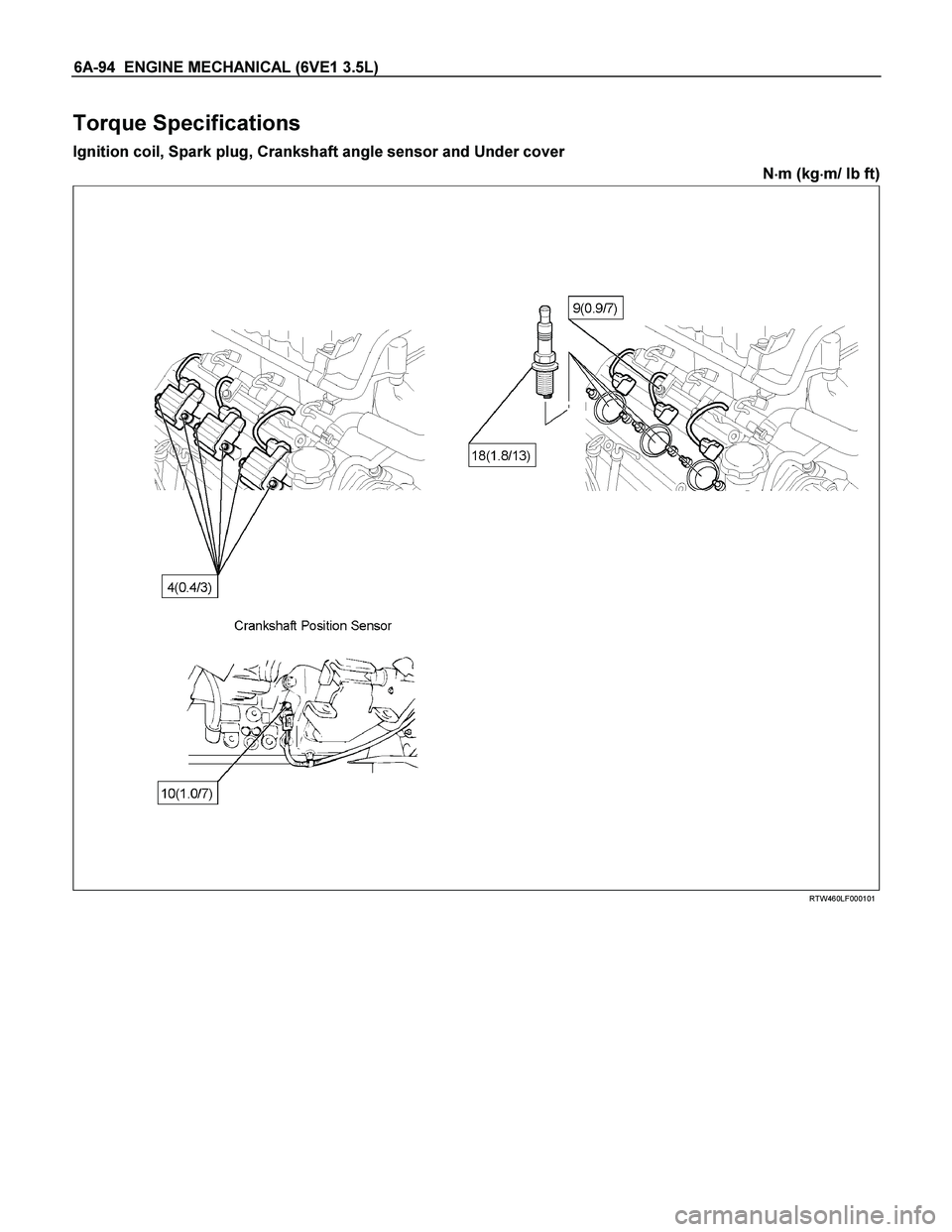
Torque Specifications
Ignition coil, Spark plug, Crankshaft angle sensor and Under cover
N�
�� �m (kg�
�� �m/ lb ft)
RTW460LF000101
Page 1951 of 4264
 6C-9
140R100028
Reuse of Quick–Connector
Replace the port and connector if scratch, dent or
crack is found.
Remove any dirt build up on the port when instal")
ENGINE FUEL (6VE1 3.5L) 6C-9
140R100028
Reuse of Quick–Connector
Replace the port and connector if scratch, dent or
crack is found.
Remove any dirt build up on the port when installing
the connector. Replace the connector, if there is any
forms of rust, dent, scratch.
After cleaning the port, insert it straight into the
connector until it clicks. After it clicks, try pulling a
t
49N (5kgf) it out to make sure that it is not drawn
and is securely locked.
140R100036
Assembling Advice
By applying engine oil or light oil to the pipe, port makes
pipe assembly easier. The pipe assembly should take
place immediately after applying oil (to prevent dus
t
from sticking to the pipe surface –which may
decrease sealing ability).
Test/Inspection After Assembling
1. Reconnect the battery negative cable.
2. Turn the ignition key to the “ON" position and listen
for pump start-up sound. Inspect for leaks, the
fuel pressure will increase as the fuel pump is
actuated.
3. Perform leak inspection (step 2) several times.
4. Start the engine and observe the engine idle speed.
The presence of dirt in the fuel system may affec
t
the fuel injection system.
Page 1952 of 4264
6C-10 ENGINE FUEL (6VE1 3.5L)
Fuel Pump Relay
General Description
In order to control the fuel pump and sender assembly
(FPAS) operation, the FPAS relay is provided. When
the starter switch is turned to “ON" position, the FPAS
relay operates the FPAS for 2 seconds.
When it is turned to “START" position, the Engine
Control Module receives the reference pulse from the
Ignition Control Module and it operates the relay, again
causing the FPAS to feed fuel.
Page 1962 of 4264

Jump Starting Procedure
1. Set the vehicle parking brake.
If the vehicle is equipped with an automatic
transmission, place the selector level in the “PAR")
6D1-4 ENGINE ELECTRICAL (6VE1 3.5L)
Jump Starting Procedure
1. Set the vehicle parking brake.
If the vehicle is equipped with an automatic
transmission, place the selector level in the “PARK"
position.
If the vehicle is equipped with a manual
transmission, place the shift lever in the
“ NEUTRAL" position.
Turn “OFF" the ignition.
Turn “OFF" all lights and any other accessory
requiring electrical power.
2. Look at the built –in hydrometer.
If the indication area of the built –in hydrometer is
completely clear, do not try to jump start.
3.
Attach the end of one jumper cable to the positive
terminal of the booster battery.
Attach the other end of the same cable to the
positive terminal of the discharged battery.
Do not allow the vehicles to touch each other. This
will cause a ground connection, effectively
neutralizing the charging procedure.
Be sure that the booster battery has a 12 volt rating.
4. Attach one end of the remaining cable to the
negative terminal of the booster battery.
Attach the other end of the same cable to a solid
engine ground (such as the air conditioning
compressor bracket or the generator mounting
bracket) of the vehicle with the discharged battery.
The ground connection must be at least 450 mm
(18 in.) from the battery of the vehicle whose battery
is being charged.
WARNING: NEVER ATTACH THE END OF THE
JUMPER CABLE DIRECTLY TO THE NEGATIVE
TERMINAL OF THE DEAD BATTERY.
5. Start the engine of the vehicle with the good battery.
Make sure that all unnecessary electrical
accessories have been turned “OFF".
6. Start the engine of the vehicle with the dead battery.
7. To remove the jumper cables, follow the above directions in reverse order.
Be sure to first disconnect the negative cable from
the vehicle with the discharged battery.
Battery Removal
P1010001
1. Remove negative cable.
2. Remove positive cable (2).
3. Remove retainer screw and rods.
4. Remove retainer.
5. Remove battery.
Battery Installation
1. Install battery.
2. Install retainer.
3. Install retainer screw and rods.
NOTE: Make sure that the rod is hooked on the body
side.
4. Install positive cable.
5. Install negative cable.
 6A-93
Main Data and Specification
General Specification
Item Specifications
Engine type, number of cylinders and arrangement Water cooled, four cycle V6
Form of")

Fuel Pump Relay
General Description
In order to control the fuel pump and sender assembly
(FPAS) operation, the FPAS relay is provided. When
the starter switch is tur")