Page 3692 of 4264

7A2-12 TRANSMISSION CONTROL SYSTEM (AW30 –40LE) (V6 3.5L)
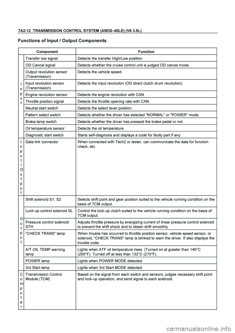
Functions of Input / Output Components
Component Function
Transfer low signal Detects the transfer High/Low position.
OD Cancel signal Detects whether the cruise control unit is judged OD cancel mode.
Output revolution sensor
(Transmission) Detects the vehicle speed.
Input revolution sensor
(Transmission) Detects the input revolution (OD direct clutch drum revolution).
Engine revolution sensor Detects the engine revolution with CAN.
Throttle position signal Detects the throttle opening rate with CAN.
Neutral start switch Detects the select lever position.
Pattern select switch Detects whether the driver has selected "NORMAL" or "POWER" mode.
Brake lamp switch Detects whether the driver has pressed the brake pedal or not.
Oil temperature sensor Detects the oil temperature.
I
n
p
u t
Diagnostic start switch Starts self-diagnosis and displays a code for faulty part if any.
I
n
p
u t
/
O
u t
p
u t Data link connector When connected with Tech2 or tester, can communicate the data for function
check, etc.
Shift solenoid S1, S2 Selects shift point and gear position suited to the vehicle running condition on the
basis of TCM output.
Lock-up control solenoid SL Control the lock-up clutch suited to the vehicle running condition on the basis of TCM output.
Pressure control solenoid
STH Adjusts throttle pressure by energizing current of linear pressure control solenoid
to prevent the shift shock and to obtain shift smoothly.
"CHECK TRANS" lamp When trouble has occurred to throttle position sensor, vehicle speed sensor, or
solenoid, "CHECK TRANS" lamp is blinked to warn the driver. If also displays the
trouble code.
A/T OIL TEMP warning
lamp Lights when ATF oil temperature rises. (Turned on at greater than 146
�
C
(295 �
F). Turned off at less than 132 �
C (270 �
F).
POWER lamp Lights when POWER MODE detected.
O
u
t
p
u
t
3rd Start lamp Lights when 3rd Start MODE detected.
C
o
m
p
u t
e r Transmission Control
Module (TCM) Based on the signal from each switch and sensors, judges necessary shift point
and lock-up operation, and send signal to each solenoid.
Page 3693 of 4264

TRANSMISSION CONTROL SYSTEM (AW30 –40LE) (V6 3.5L) 7A2-13
CAN bus systems in automatic
transmission control (AW30-40LE)
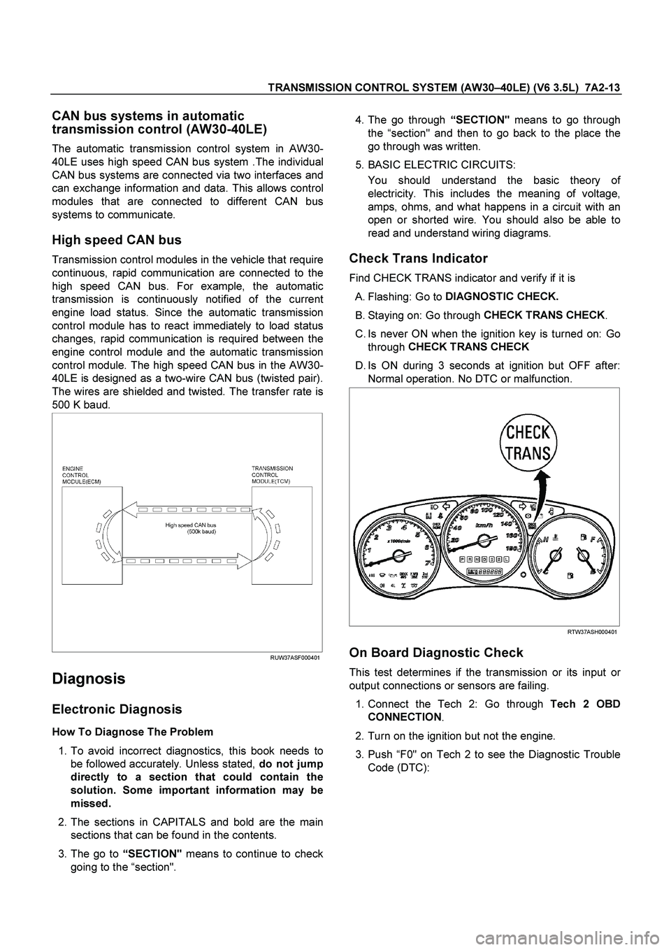
The automatic transmission control system in AW30-
40LE uses high speed CAN bus system .The individual
CAN bus systems are connected via two interfaces and
can exchange information and data. This allows control
modules that are connected to different CAN bus
systems to communicate.
High speed CAN bus
Transmission control modules in the vehicle that require
continuous, rapid communication are connected to the
high speed CAN bus. For example, the automatic
transmission is continuously notified of the current
engine load status. Since the automatic transmission
control module has to react immediately to load status
changes, rapid communication is required between the
engine control module and the automatic transmission
control module. The high speed CAN bus in the AW30-
40LE is designed as a two-wire CAN bus (twisted pair).
The wires are shielded and twisted. The transfer rate is
500 K baud.
RUW37ASF000401
Diagnosis
Electronic Diagnosis
How To Diagnose The Problem
1. To avoid incorrect diagnostics, this book needs to
be followed accurately. Unless stated, do not jump
directly to a section that could contain the
solution. Some important information may be
missed.
2. The sections in CAPITALS and bold are the main
sections that can be found in the contents.
3. The go to “
SECTION"
means to continue to check
going to the “section".
4. The go through “
SECTION"
means to go through
the “section" and then to go back to the place the
go through was written.
5. BASIC ELECTRIC CIRCUITS:
You should understand the basic theory o
f
electricity. This includes the meaning of voltage,
amps, ohms, and what happens in a circuit with an
open or shorted wire. You should also be able to
read and understand wiring diagrams.
Check Trans Indicator
Find CHECK TRANS indicator and verify if it is
A. Flashing: Go to DIAGNOSTIC CHECK.
B. Staying on: Go through CHECK TRANS CHECK
.
C. Is never ON when the ignition key is turned on: Go through CHECK TRANS CHECK
D. Is ON during 3 seconds at ignition but OFF after: Normal operation. No DTC or malfunction.
RTW37ASH000401
On Board Diagnostic Check
This test determines if the transmission or its input or
output connections or sensors are failing.
1. Connect the Tech 2: Go through Tech 2 OBD
CONNECTION .
2. Turn on the ignition but not the engine.
3. Push “F0" on Tech 2 to see the Diagnostic Trouble
Code (DTC):
Page 3694 of 4264
7A2-14 TRANSMISSION CONTROL SYSTEM (AW30 –40LE) (V6 3.5L)
4. Do you have a DTC?
YES: write down all code numbers and do the DTC
CHECK
NO: the DTC can not help you find the problem.
1. Go through “
CHECK TRANS" CHECK
2. If it is flashing and the flash is 0.4 seconds ON
and 0.4 seconds OFF, this means that you
should have a DTC stored. Please recheck go
to DIAGNOSTIC CHECK
and if you find the
same problem, replace the Powertrain Control
Module (TCM).
Normal
C07RY005-1
Abnormal
C07RY00042-1
“Check Trans" Check
1. Indicator is ON during 3 seconds at ignition but it is
OFF after the engine starts. The indicator is
working normally go to DIAGNOSTIC CHECK
.
RTW37ASH000401
Normal
C07RY005-1
Page 3695 of 4264

TRANSMISSION CONTROL SYSTEM (AW30 –40LE) (V6 3.5L) 7A2-15
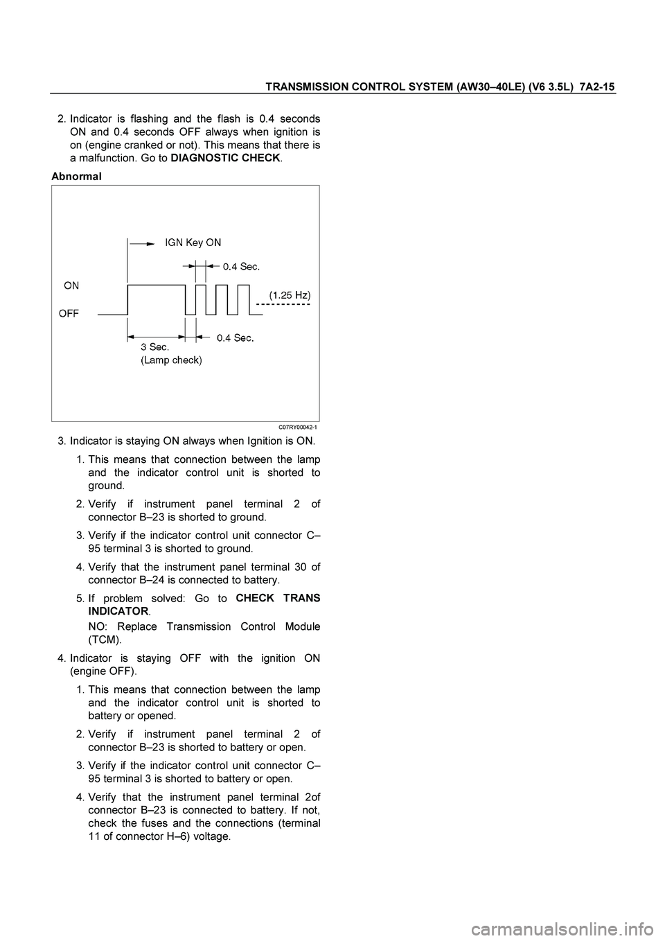
2. Indicator is flashing and the flash is 0.4 seconds
ON and 0.4 seconds OFF always when ignition is
on (engine cranked or not). This means that there is
a malfunction. Go to DIAGNOSTIC CHECK
.
Abnormal
C07RY00042-1
3. Indicator is staying ON always when Ignition is ON.
1. This means that connection between the lamp
and the indicator control unit is shorted to
ground.
2. Verify if instrument panel terminal 2 o
f
connector B –23 is shorted to ground.
3. Verify if the indicator control unit connector C –
95 terminal 3 is shorted to ground.
4.
Verify that the instrument panel terminal 30 of
connector B –24 is connected to battery.
5. If problem solved: Go to CHECK TRANS
INDICATOR .
NO: Replace Transmission Control Module
(TCM).
4. Indicator is staying OFF with the ignition ON
(engine OFF).
1. This means that connection between the lamp
and the indicator control unit is shorted to
battery or opened.
2.
Verify if instrument panel terminal 2 of
connector B –23 is shorted to battery or open.
3. Verify if the indicator control unit connector C –
95 terminal 3 is shorted to battery or open.
4.
Verify that the instrument panel terminal 2of
connector B –23 is connected to battery. If not,
check the fuses and the connections (terminal
11 of connector H –6) voltage.
Page 3696 of 4264
7A2-16 TRANSMISSION CONTROL SYSTEM (AW30 –40LE) (V6 3.5L)
5. If problem solved: Go to CHECK TRANS
INDICATOR .
NO: Replace Transmission Control Module
(TCM).
RTW37LF000701
Page 3697 of 4264
TRANSMISSION CONTROL SYSTEM (AW30 –40LE) (V6 3.5L) 7A2-17
Tech 2 OBD Connection
In order to access OBD Transmission Control Module
(TCM) data, use of the Tech 2 scan tool kit (7000086)
is required.
1. The electronic diagnosis equipment is composed of:
1. Tech 2 hand held scan tool unit (7000057) and
DLC cable (3000095).
901RW176
2. SAE 16/19 Pin Adapter (3000098)(1), RS232
Loop Back Connector (3000112)(2), and
PCMCIA Card (3000117)(3).
F07RW033
Page 3707 of 4264

TRANSMISSION CONTROL SYSTEM (AW30 –40LE) (V6 3.5L) 7A2-27
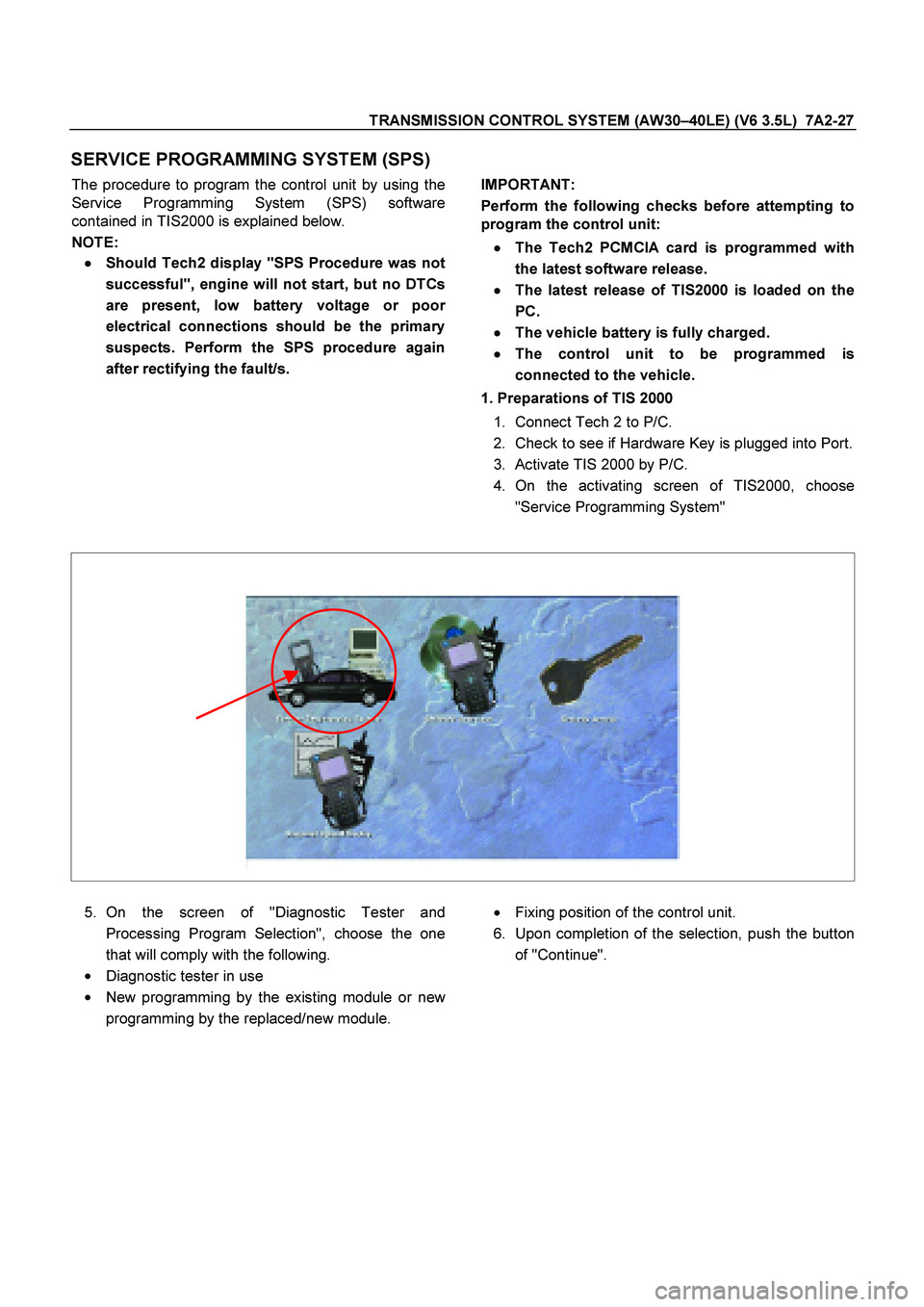
SERVICE PROGRAMMING SYSTEM (SPS)
The procedure to program the control unit by using the
Service Programming System (SPS) software
contained in TIS2000 is explained below.
NOTE: �
� �
�
Should Tech2 display "SPS Procedure was not
successful", engine will not start, but no DTCs
are present, low battery voltage or poo
r
electrical connections should be the primary
suspects. Perform the SPS procedure again
after rectifying the fault/s.
IMPORTANT:
Perform the following checks before attempting to
program the control unit:
�
� �
�
The Tech2 PCMCIA card is programmed with
the latest software release.
�
� �
�
The latest release of TIS2000 is loaded on the
PC.
�
� �
�
The vehicle battery is fully charged.
�
� �
�
The control unit to be programmed is
connected to the vehicle.
1. Preparations of TIS 2000
1.
Connect Tech 2 to P/C.
2.
Check to see if Hardware Key is plugged into Port.
3.
Activate TIS 2000 by P/C.
4.
On the activating screen of TIS2000, choose
"Service Programming System"
5.
On the screen of "Diagnostic Tester and
Processing Program Selection", choose the one
that will comply with the following.
�
Diagnostic tester in use
�
New programming by the existing module or new
programming by the replaced/new module.
�
Fixing position of the control unit.
6.
Upon completion of the selection, push the button
of "Continue".
Page 3710 of 4264
7A2-30 TRANSMISSION CONTROL SYSTEM (AW30 –40LE) (V6 3.5L)
OBD Diagnostic Management System
Transmission Control Module (TCM) Location
P1010052
RTW37ASH000301