Page 3700 of 4264
7A2-20 TRANSMISSION CONTROL SYSTEM (AW30 –40LE) (V6 3.5L)
RTW37ALH000101
Once the test vehicle has been identified an
“ Application (Powertrain) Menu" screen appears.
Please select the appropriate application.
The following table shows, which functions are used fo
r
the available equipment versions.
F0: Diagnostic Trouble Codes
F0: Read DTC Info As stored By ECU
F1: Clear DTC Information
F2: DTC Information
F1: Data Display
F2: Snap Shot
F3: Miscllaneous Tests
F0: Lamps
F0: Power Lamp Test
F1: 3rd start Lamp Test
F2: AT Oil Temperature Lamp
F3: Check Light
F1: Solenoids
F0: Shift solenoid A (S1)
F1: Shift Solenoid B (S2)
F2: Pressure Control Solenoid (PCS)
Page 3703 of 4264
TRANSMISSION CONTROL SYSTEM (AW30 –40LE) (V6 3.5L) 7A2-23
SNAPSHOT DISPLAY WITH TIS2000
Procedures for transferring and displaying Tech2
snapshot data by using TIS2000 [Snapshot Upload]
function is described below.
Snapshot data can be displayed with [Snapshot
Upload] function included in TIS2000.
By analyzing these data in various methods, trouble
conditions can be checked.
Snapshot data is displayed by executing the three steps
below shown:
1. Record the snapshot data, in Tech2.
2. Transfer the snapshot data to PC.
Page 3717 of 4264

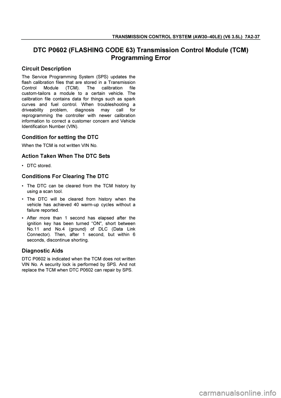
TRANSMISSION CONTROL SYSTEM (AW30–40LE) (V6 3.5L) 7A2-37
DTC P0602 (FLASHING CODE 63) Transmission Control Module (TCM)
Programming Error
Circuit Description
The Service Programming System (SPS) updates the
flash calibration files that are stored in a Transmission
Control Module (TCM). The calibration file
custom-tailors a module to a certain vehicle. The
calibration file contains data for things such as spark
curves and fuel control. When troubleshooting a
driveability problem, diagnosis may call fo
r
reprogramming the controller with newer calibration
information to correct a customer concern and Vehicle
Identification Number (VIN).
Condition for setting the DTC
When the TCM is not written VIN No.
Action Taken When The DTC Sets
DTC stored.
Conditions For Clearing The DTC
The DTC can be cleared from the TCM history by
using a scan tool.
The DTC will be cleared from history when the
vehicle has achieved 40 warm-up cycles without a
failure reported.
After more than 1 second has elapsed after the
ignition key has been turned “ON", short between
No.11 and No.4 (ground) of DLC (Data Link
Connector). Then, after 1 second, but within 6
seconds, discontinue shorting.
Diagnostic Aids
DTC P0602 is indicated when the TCM does not written
VIN No. A security lock is performed by SPS. And not
replace the TCM when DTC P0602 can repair by SPS.
Page 3718 of 4264

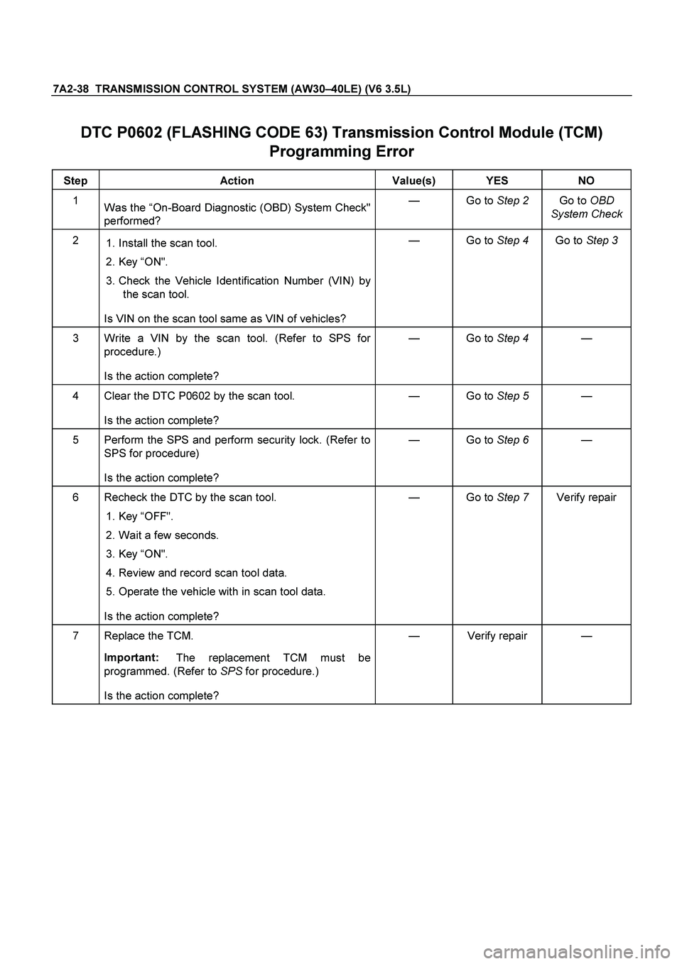
7A2-38 TRANSMISSION CONTROL SYSTEM (AW30–40LE) (V6 3.5L)
DTC P0602 (FLASHING CODE 63) Transmission Control Module (TCM)
Programming Error
Step Action Value(s) YES NO
1
Was the “On-Board Diagnostic (OBD) System Check"
performed? — Go to Step 2 Go to OBD
System Check
2
1. Install the scan tool.
2. Key “ON".
3. Check the Vehicle Identification Number (VIN) by
the scan tool.
Is VIN on the scan tool same as VIN of vehicles? — Go to Step 4 Go to Step 3
3 Write a VIN by the scan tool. (Refer to SPS for
procedure.)
Is the action complete? — Go to Step 4 —
4 Clear the DTC P0602 by the scan tool.
Is the action complete? — Go to Step 5 —
5 Perform the SPS and perform security lock. (Refer to
SPS for procedure)
Is the action complete? — Go to Step 6 —
6 Recheck the DTC by the scan tool.
1. Key “OFF".
2. Wait a few seconds.
3. Key “ON".
4. Review and record scan tool data.
5. Operate the vehicle with in scan tool data.
Is the action complete? — Go to Step 7 Verify repair
7 Replace the TCM.
Important:
The replacement TCM must be
programmed. (Refer to SPS for procedure.)
Is the action complete? — Verify repair —
Page 3778 of 4264
7A3-22 ON-VEHICLE SERVICE (AW30 –40LE)
ATF Replacement
Inspection
NOTE: Do not overfill.
1. Remove the drain plug from oil pan and drain the
fluid.
RUW17ASH013401
2. Reinstall the drain plug securely.
Torque: 19 N �
��
�
m (14 Ib ft)
3. With the engine OFF, add new fluid through the fille
r
tube.
Drain and refill 5.2 liter
Dry fill 8.7 liter
Fluid BESCO ATF III
4. Start the engine and shift the selector into all
position from “P" through “L", and then shift into “P".
5. With the engine idling, check the fluid level. Add fluid up to the “COLD" level on the dipstick.
6. The ATF level must be checked again for correct level with the “HOT" level.
NOTE: To prevent fluid leaks, the drain plug gasket
must be replaced each time this plug is removed.
Page 3785 of 4264

ON-VEHICLE SERVICE (AW30 –40LE) 7A3-29
8.
Remove the upper housing (held in place by 4
latched fasteners).
9.
Remove the spring plate.
10.
Remove the grooved pin.
11.
Remove the lever assembly by pressing the rod
down (lever in N position).
12.
If lamp replacement is required, remove the lamp
assembly from the lamp socket (align the socke
t
grooved portion and the lamp assembly protruding
portion).
Install or Connect
NOTE
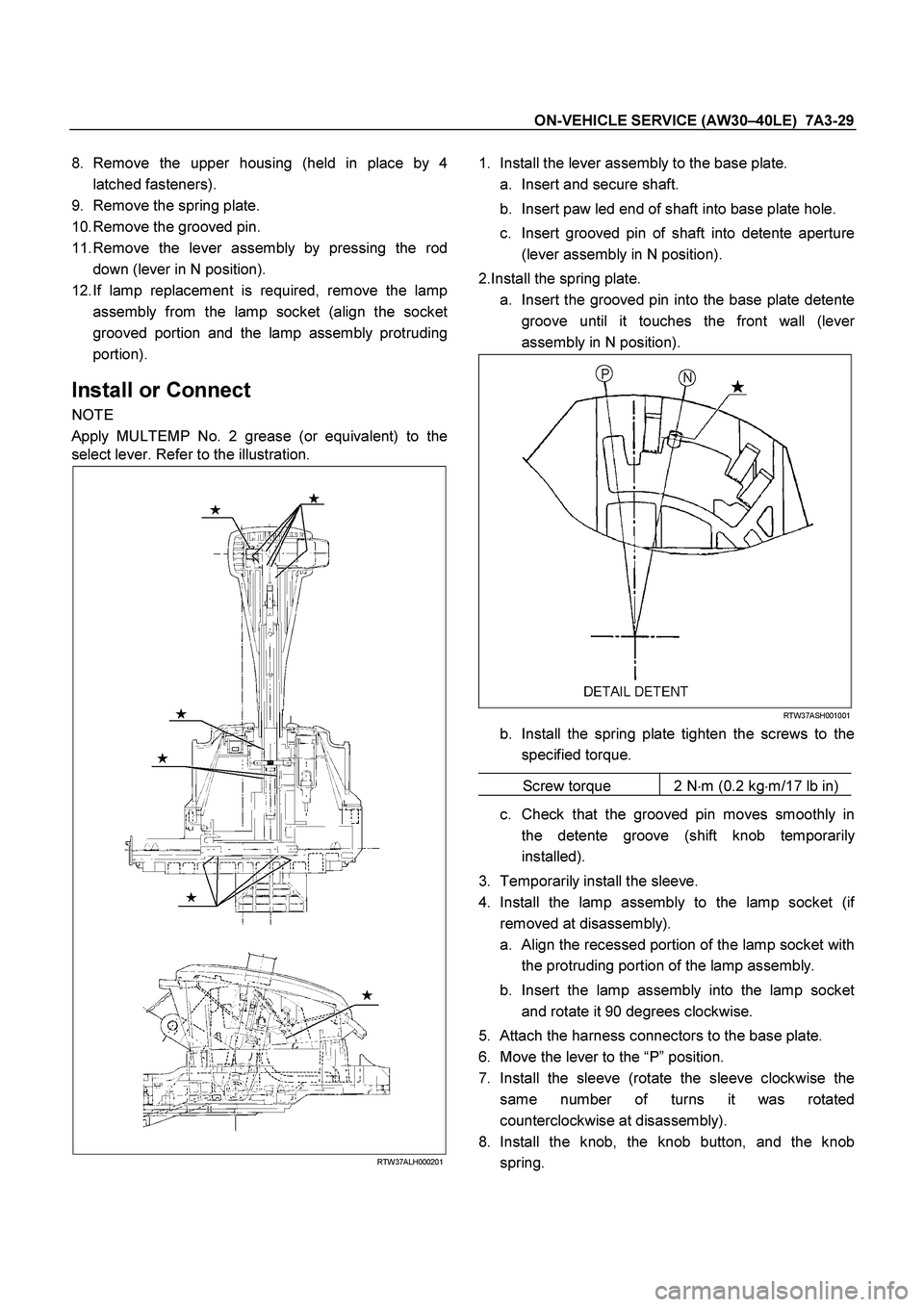
Apply MULTEMP No. 2 grease (or equivalent) to the
select lever. Refer to the illustration.
RTW37ALH000201
1.
Install the lever assembly to the base plate.
a.
Insert and secure shaft.
b.
Insert paw led end of shaft into base plate hole.
c.
Insert grooved pin of shaft into detente aperture
(lever assembly in N position).
2.Install the spring plate. a.
Insert the grooved pin into the base plate detente
groove until it touches the front wall (leve
r
assembly in N position).
RTW37ASH001001
b.
Install the spring plate tighten the screws to the
specified torque.
Screw torque 2 N �
m (0.2 kg �
m/17 lb in)
c.
Check that the grooved pin moves smoothly in
the detente groove (shift knob temporaril
y
installed).
3.
Temporarily install the sleeve.
4.
Install the lamp assembly to the lamp socket (i
f
removed at disassembly).
a.
Align the recessed portion of the lamp socket with
the protruding portion of the lamp assembly.
b.
Insert the lamp assembly into the lamp socket
and rotate it 90 degrees clockwise.
5.
Attach the harness connectors to the base plate.
6.
Move the lever to the “P ” position.
7.
Install the sleeve (rotate the sleeve clockwise the
same number of turns it was rotated
counterclockwise at disassembly).
8.
Install the knob, the knob button, and the knob
spring.
Page 3786 of 4264
7A3-30 ON-VEHICLE SERVICE (AW30 –40LE)
9.
Adjust the clearance (2) between the detente plate
and the pin by moving the select lever knob sleeve
(1).
Detente plate and pin clearance
mm(in
)
0.2 - 1.0 (0.01 - 0.04)
255R300002
10.
Install the 2 screws securing the knob and tighten
them to the specified torque.
Screw torque: 2 N �
m (0.2kg �
m/17 lb in)
11.
Install the upper housing. Make sure that the 4
latched fasteners are securely closed.
Page 3788 of 4264

7A3-32 ON-VEHICLE SERVICE (AW30 –40LE)
Install or Connect
1.
Install the shift cable toward the inside of the cabin
from the bottom of the vehicle.
2.
Push the shift cable into the select lever base.
3.
Connect the shift cable to the select lever.
4.
Fix the shift cable to the bracket.
Install the clip on the marking of shift cable.
5.
Check that the select lever is in the “N ” position.
6.
Check that the transmission is in the “N ” position.
249R300002
7.
Slide the cover in the direction shown by the arrow
(1).
8.
Use an ordinary screwdriver to move the lock piece
from the position indicated by the arrow (2). Continue
to move the lock piece until the adjuster position
begins to change.
P1010012
9.
Connect the shift cable to the manual shaft select
lever at the transmission side.
10.
Insert the lock piece to the adjuster (cable length
adjustment).
11.
Slide the cover on the adjuster and secure lock
piece.
P1010016-2
11.
Press the select lever knob button 5 times.
Then check that the select lever moves smoothly to each of its positions.
13.
Check that the shift position indicated by the select
lever and the actual shift position are the same.
14.
Install the front console and rear console.
15.
Connect the negative battery cable.
16.
Remove the wheel blocks.