Page 3363 of 4264
ANTITHEFT SYSTEM 11B – 17
ALARM
TRIGGER7
B-440.5
B 0.5
Y/L 0.5
R/Y
0.85
B0.5
B 0.5
G/Y0.5
G0.5
G
0.5
G/Y2
W
10A
HAZARDEB-16
1.25
B
C-2B-58 C-15
ENGINE
ROOM-RHH-183 H-712
28
B-44
B-43
11 B-43 UNLOCK
8 B-43 LOCK
7 B-44
18 B-44 UNLOCK
16 B-44 LOCK
151
X-9 3
X-9
4 X-9
2 X-9
HAZARD
RELAY-LHHAZARD
RELAY-RH
HAZARD SW
1
X-10 3
X-10
4 X-10
2 X-10
DATA LINK
CONNECTOR
RR COMBI
LHRR COMBI
RH
B-73 D-241
D-24 D-4D-243 H-102
H-109
D-44
D-41
D-43 H-105
H-248
H-108
0.5
L/R1.25
L/R 1.25
L/R
1.25
L 0.5
L/Y0.5
L/Y
0.5
BR/B
22
LOCK
UN LOCK
KEY
CYLINDER
SW.
DOOR LOCK
ACTUATOR
DRIVER
0.5
B0.5
BFLASHER
CONTROL
ANTI THEFT C/U(with KEYLESS ENTRY)
1 3 4
5
7 89
10
11 12
13 14 15
162
6 B-56310A
METER (+B)
2
B
2
B
C-2
ENGINE
ROOM-RH B-44
6
C-2
ENGINE
ROOM-RHH-185 0.85 B
0.5BR/R
0.5
BR/R
0.5
B 0.5
B
1.25
B 0.5LG/WWELD
SPLICEB-73
WELD
SPLICEB-73 WELD
SPLICEB-73 D-261
D-26 D-9D-263 H-132
H-139
D-94
D-91
D-93 H-135
H-258
H-138
0.5
L/R1.25
L/R1.25
L 1.25L
1.25L/R
0.5BR/B
1.25L
1.25L/R
0.5BR/B
0.5
L/Y0.5
BR/B
22
LOCK
UN LOCK
KEY
CYLINDER
SW.
DOOR LOCK
ACTUATOR
PASSENGER
0.5
B0.5
B
WELD
SPLICED-18
D-184
D-181
D-183 H-265
H-2615
H-261
H-166
H-163
H-162
1.25
L/R1.25
L 0.5
BR/B1.25
L/R1.25
L
0.5
BR/B 1.25
L/R1.25
L 0.5
BR/B
2
LOCK
UN LOCK
DOOR LOCK
ACTUATOR
RR-RH
1.25
L/WD-14
D-144
D-141
D-143 H-146
H-143
H-142
1.25
L/R1.25
L 1.25
BR/B
2
5H-26
LOCK
UN LOCK
DOOR LOCK
ACTUATOR
RR-LH
ANTI THEFT INDICATOR
ENGINE HOOD SW
1.25
L/W
1.25
B
2B 1.25B
A
C-301 H-188
2 C-30
B-44
11
C-2
ENGINE
ROOM-RH
ENGINE
ROOM-RH
B-521
2 B-52
H-18
H-183
H-147
6 H-167
C-2
RTW48AXF024001
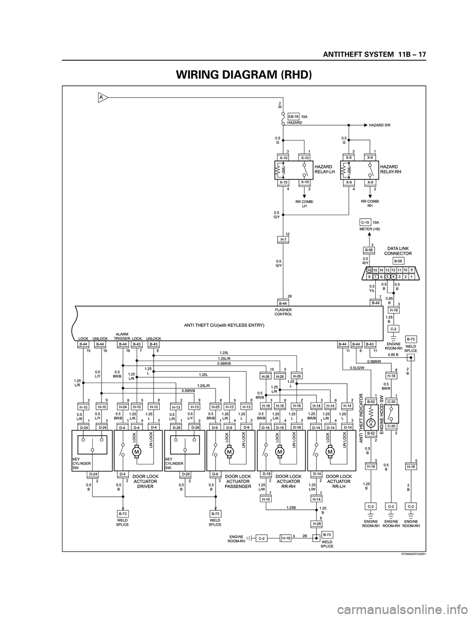
WIRING DIAGRAM (RHD)
Page 3364 of 4264
11B – 18 ANTITHEFT SYSTEM
A
DOOR SW-DR
B-73
DOOR SW-PASSDOOR SW-RR RHDOOR SW-RR LH
L-7
0.5
B/W0.5
B/W0.5
B/W
0.5
R/G0.5
R/G0.5
R/G 0.5
R/G0.5
R/G
1
ALARMER C/U
(BUZZER)
1=with ALARMER C/U(BUZZER) only0.5
R/G0.5
R/G0.5
R/W
1.25
B
1.25
B
2.0
B
2.0
B
DOME
LIGHTHORN;
ANTI THEFT
L-91
H-185 L-9
2
RR DEF
(1)
WELD
SPLICE MAP
LIGHT
C-2
ENGINE �
ROOM RH
R-62
R-61
R-11
R-101
R-91 2
H-26L-11
L-1
2
H-1210
H-127R-1R-10R-9
0.5
R/B0.5
R/B
0.5
R/B0.5
R/B
2 2 2
9
H-2614
H-2613
H-26
C-11 10A
AUDIO
2 B-56 3
B-624 2
B-62 B-62
3 B-63
P-6P-5
8
BIG.1IG.2 MAIN
20
B/Y8
B/R
3
W/B
3
W3
W/B
3
B/Y
0.5
R/Y0.5
R/W0.5
R/W0.85R/Y
1.25
LG/W 5
W
P-11
C-108 2
C-108
B1 B2
IG1 IG2 ACCOFF
ST
P-10P-2SBF-180A (4JA1/4JH1)
100A (6VE1/C24SE)
DOOR LOCKC-14
20A
ANTI THEFTC-17
10A
ROOM LAMPC-16
10A SBF-540A50A
SBF-9
BODY ENGINE
JANCTION BLOCK
B-56
8
B-43
2B-43
6
H-104
H-247
D-207
BD-206H-134
H-257
D-103
D-104B-44
1B-44
2 4
B-445
B-442
C-117
5
H-12 9
B-43 3
B-43B-55
4B-56C-108
4
H-181 C-117
1 6
AUTO DOOR LOCK SW.
DRIVER SIDE
AUTO DOOR LOCK SW.
PASSENGER SIDE
0.5
LG/R
0.5
LG/R0.5
LG/R 0.5
R/L
0.5
R/L0.5
R/L
(POWER WINDOW SW.)
LOCK UN LOCK
WITH POWER WINDOW
DOOR LOCK
MOTORB ACC
ANTI THEFT C/U with SUPER LOCK STARTER
SW.
3
L
POWER
SUPPLY
RTW48AXF025401
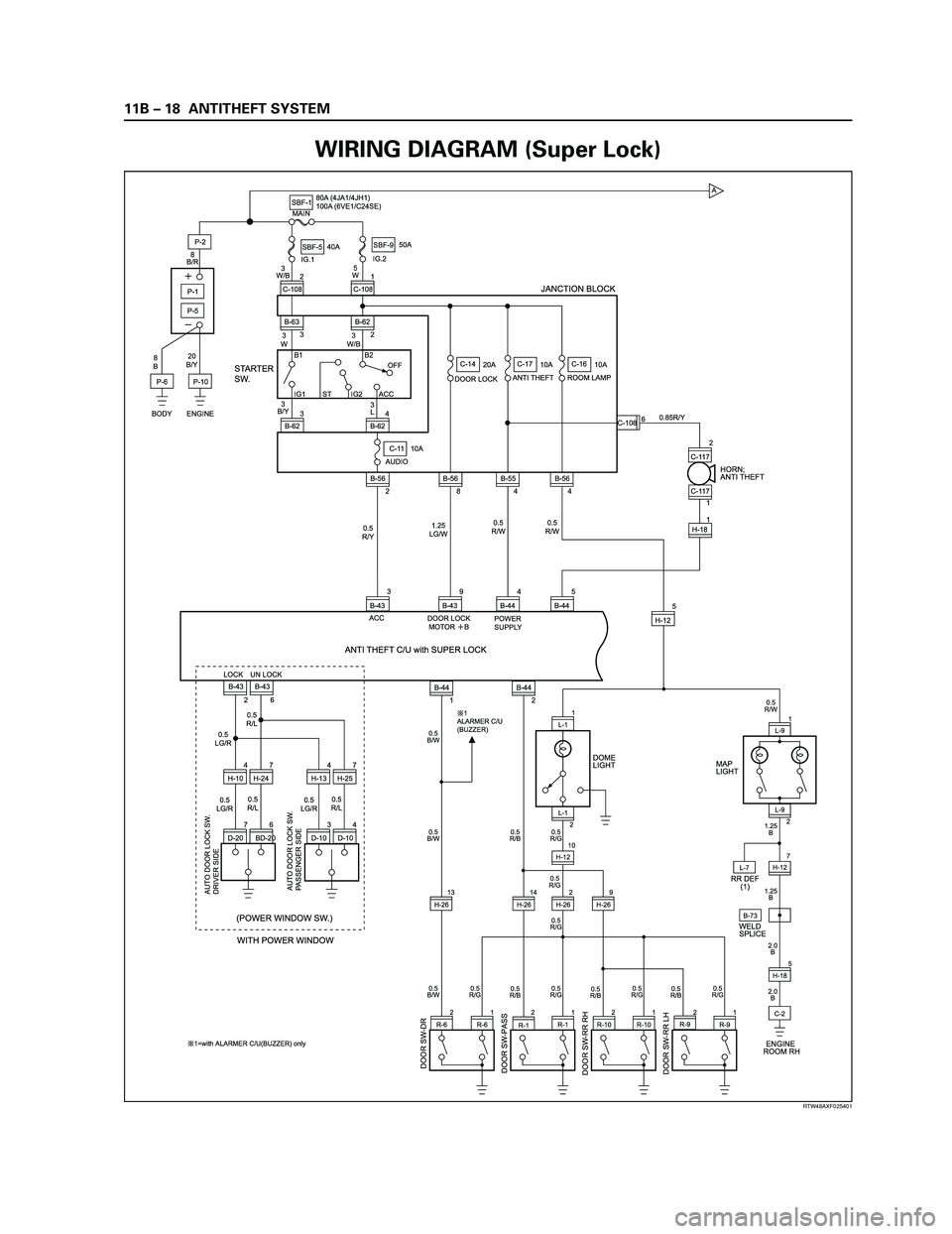
WIRING DIAGRAM (Super Lock)
Page 3365 of 4264
ANTITHEFT SYSTEM 11B – 19
RTW48AXF024801
0.5
G/Y0.5
G0.5
G
0.5
G/Y2
W
10A
HAZARDEB-16
H-712
28
B-44
B-43 UNLOCK SUPER LOCK
8B-44
24 B-43 LOCK ALARM
TRIGGER
7 B-44
18 B-44 LOCK
151
X-9 3
X-9
4 X-9
2 X-9
HAZARD
RELAY-LHHAZARD
RELAY-RH
HAZARD SW
1
X-10 3
X-10
4 X-10
2 X-10
RR COMBI
LHRR COMBI
RH
B-73 D-241
D-24 D-23 H-102
D-231
D-234
D-232 H-105
H-248
H-108
H-2410
0.5
L/R1.25
L/R 1.25
L/R
1.25
L 0.5
BR/B
27
LOCK
UN LOCK
D-236
D-233
LOCK UN LOCK
KEY
CYLINDER
SW.
DOOR LOCK
ACTUATOR
DRIVER
0.5
B0.5
BFLASHER
CONTROL
ANTI THEFT C/U with SUPER LOCK
WELD
SPLICEB-73 D-261
D-26 D-25 H-132
D-251
D-254
D-252 H-135
H-258
H-138
0.5
L/R1.25
L/R1.25
L 1.25L
1.25L/R
0.5BR/B
1.25L
1.25O
1.25L/R
0.5
BR/B
27
LOCK
UN LOCK
D-256
D-253 H-2510
LOCK UN LOCK
KEY
CYLINDER
SW.
DOOR LOCK
ACTUATOR
PASSENGER
0.5
B0.5
B
WELD
SPLICE 1.25
L/R1.25
L
0.5
BR/B
A
D
E CB
RTW48AXF024801
WIRING DIAGRAM (Super Lock)
Page 3366 of 4264
11B – 20 ANTITHEFT SYSTEM
RTW48AXF024901
ANTI THEFT INDICATOR
ENGINE HOOD SW
7
B-440.5
B 0.5
Y/L
0.3
V0.5
R/Y
0.85
B0.5
B
1.25
B
C-2B-58 C-15
ENGINE
ROOM-RHH-183
B-43
11
DATA LINK
CONNECTOR
IMMOBILIZER C/U
ANTI THEFT C/U with SUPER LOCK
1 3 4
5
7 89
10
11 12
13 14 15
162
6 B-563
9
B-44 B-68
610A
METER (+B)
2
B
2
B
C-2
ENGINE
ROOM-RH B-44
6
C-2
ENGINE
ROOM-RHH-185 0.85 B
0.5BR/R
0.5
BR/R
0.5
B 0.5
B
1.25
B 0.5LG/WWELD
SPLICEB-73
WELD
SPLICEB-73 D-18
D-271
D-274
D-272 H-265
H-2615
H-261
H-166
H-163
H-162
1.25
L/R1.25
L 0.5
BR/B1.25
L/R1.25
L
0.5
BR/B
7
LOCK
UN LOCKLOCK UN LOCKLOCK UN LOCK
DOOR LOCK
ACTUATOR
RR-RH
1.25
L/WD-14
D-281
D-284
D-282 H-146
H-143
H-142
1.25
L/R1.25
L
D-283
D-286H-147
D-273 H-269
D-276H-167
1.25
BR/B
2
5H-26
LOCK
UN LOCK
DOOR LOCK
ACTUATOR
RR-LH
1.25
L/W
1.25
B
2B 1.25B
E
B
C
D
C-301 H-188
2 C-30
B-44
11
C-2
ENGINE
ROOM-RH
ENGINE
ROOM-RH
B-521
2 B-52
H-18
H-183
H-147
6 H-167
C-2
RTW48AXF024901
WIRING DIAGRAM (Super Lock)
Page 3461 of 4264
POWER-ASSISTED STEERING SYSTEM 3B-31
Supplemental Restraint System Steering Wheel & Column
Service Precaution
This steering wheel and column repair section covers
the Supplemental Restraint System (SRS) steering
column. The following repair procedures are specific to
SRS components. When servicing a vehicle equipped
with Supplemental Restraint System, pay close attention
to all WARNINGS and CAUTIONS.
For detailed explanation about SRS, refer to Restraints
section.
WARNING: THIS VEHICLE HAS A SUPPLEMENTAL
RESTRAINT SYSTEM (SRS). REFER TO THE SRS
COMPONENT AND WIRING LOCATION VIEW IN
ORDER TO DETERMINE WHETHER YOU ARE
PERFORMING SERVICE ON OR NEAR THE SRS
COMPONENTS OR THE SRS WIRING. WHEN YOU
ARE PERFORMING SERVICE ON OR NEAR THE
SRS COMPONENTS OR THE SRS WIRING, REFE
R
TO THE SRS SERVICE INFORMATION. FAILURE TO
FOLLOW WARNINGS COULD RESULT IN POSSIBLE
AIR BAG DEPLOYMENT, PERSONAL INJURY, O
R
OTHERWISE UNNEEDED SRS SYSTEM REPAIRS.
SAFE HANDLING OF INFLATOR MODULES
REQUIRES FOLLOWING THE PROCEDURES
DESCRIBED BELOW FOR BOTH LIVE AND
DEPLOYED MODULES.
SAFETY PRECAUTIONS MUST BE FOLLOWED
WHEN HANDLING A DEPLOYED AIR BAG
ASSEMBLY (AIR BAG). AFTER DEPLOYMENT, THE
AIR BAG ASSEMBLY (AIR BAG) SURFACE MAY
CONTAIN A SMALL AMOUNT OF SODIUM
HYDROXIDE, A BY-PRODUCT OF THE
DEPLOYMENT REACTION, THAT IS IRRITATING TO
THE SKIN AND EYES. MOST OF THE POWDER ON
THE AIR BAG ASSEMBLY (AIR BAG) IS HARMLESS.
AS A PRECAUTION, WEAR GLOVES AND SAFETY
GLASSES WHEN HANDLING A DEPLOYED AIR BAG
ASSEMBLY, AND WASH YOUR HANDS WITH MILD
SOAP AND WATER AFTERWARDS.
WHEN CARRYING A LIVE AIR BAG ASSEMBLY,
MAKE SURE THE BAG AND TRIM COVER ARE
POINTED AWAY FROM YOU. NEVER CARRY AN AI
R
BAG ASSEMBLY BY THE WIRES OR CONNECTO
R
ON THE UNDERSIDE OF MODULE. IN THE CASE OF
AN ACCIDENTAL DEPLOYMENT, THE BAG WILL
THEN DEPLOY WITH MINIMAL CHANCE OF INJURY.
WHEN PLACING A LIVE AIR BAG ASSEMBLY ON A
BENCH OR OTHER SURFACE, ALWAYS FACE THE
BAG AND TRIM COVER UP, AWAY FROM THE
SURFACE.
NEVER REST A STEERING COLUMN ASSEMBLY
ON THE STEERING WHEEL WITH THE AIR BAG
ASSEMBLY FACE DOWN AND COLUMN VERTICAL.
THIS IS NECESSARY SO THAT A FREE SPACE IS
PROVIDED TO ALLOW THE AIR BAG ASSEMBLY
TO EXPAND IN THE UNLIKELY EVENT OF
ACCIDENTAL DEPLOYMENT. OTHERWISE,
PERSONAL INJURY COULD RESULT.
TO AVOID DEPLOYMENT WHEN
TROUBLESHOOTING THE SRS SYSTEM, DO NOT
USE ELECTRICAL TEST EQUIPMENT, SUCH AS
BATTERY-POWERED OR A/C-POWERED VOLT-
METER, OHMMETER, ETC., OR ANY TYPE OF
ELECTRICAL EQUIPMENT OTHER THAN SPECIFIED
IN THIS MANUAL. DO NOT USE A NON-POWERED
PROBE-TYPE TESTER.
INSTRUCTIONS IN THIS MANUAL MUST BE
FOLLOWED CAREFULLY, OTHERWISE PERSONAL
INJURY MAY RESULT.
SRS Connectors
CAUTION: The special yellow color connectors are
used for supplemental restraint system-air bag
circuit.
When removing the cable harness, do not pull the
cables. Otherwise, cable disconnection may occur.
When connect the SRS connector, insert the
connector completely. Imperfect locking may cause
malfunction of SRS circuit.
Page 3470 of 4264
3B-40 POWER-ASSISTED STEERING SYSTEM
430RX005-X
14. Remove steering column cover.
15. Disconnect the wiring harness connectors located
under the steering column then remove combination
switch and SRS coil assembly.
Installation
1. Align the setting marks made when removing then
install steering wheel.
Refer to the adjustment method in case a mark is
not attached in this section.
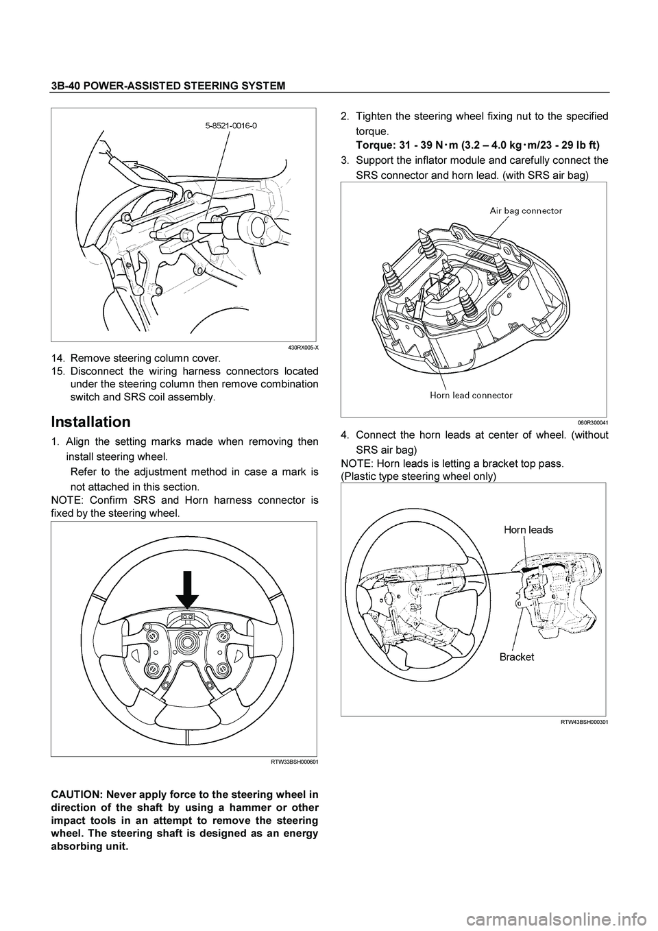
NOTE: Confirm SRS and Horn harness connector is
fixed by the steering wheel.
RTW33BSH000601
CAUTION: Never apply force to the steering wheel in
direction of the shaft by using a hammer or othe
r
impact tools in an attempt to remove the steering
wheel. The steering shaft is designed as an energy
absorbing unit.
2. Tighten the steering wheel fixing nut to the specified
torque.
Torque: 31 - 39 N�
�� �
m (3.2 – 4.0 kg�
�� �
m/23 - 29 lb ft)
3. Support the inflator module and carefully connect the
SRS connector and horn lead. (with SRS air bag)
060R300041
4. Connect the horn leads at center of wheel. (without
SRS air bag)
NOTE: Horn leads is letting a bracket top pass.
(Plastic type steering wheel only)
RTW43BSH000301
Page 3476 of 4264
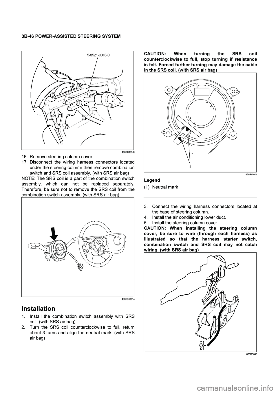
3B-46 POWER-ASSISTED STEERING SYSTEM
CAUTION:
When turning the SRS coil
counterclockwise to full, stop turning if resistance
is felt. Forced further turning may damage the cable
in the SRS coil.
(with SRS air bag)
826RW014
Legend
(1) Neutral mark
430RX005-X
16. Remove steering column cover.
17. Disconnect the wiring harness connectors located
under the steering column then remove combination
switch and SRS coil assembly. (with SRS air bag)
NOTE: The SRS coil is a part of the combination switch
assembly, which can not be replaced separately.
Therefore, be sure not to remove the SRS coil from the
combination switch assembly. (with SRS air bag)
430R300014
Installation
1. Install the combination switch assembly with SRS
coil. (with SRS air bag)
2. Turn the SRS coil counterclockwise to full, return
about 3 turns and align the neutral mark. (with SRS
air bag)
3. Connect the wiring harness connectors located at
the base of steering column.
4. Install the air conditioning lower duct.
5. Install the steering column cover.
CAUTION:
When installing the steering column
cover, be sure to wire (through each harness) as
illustrated so that the harness starter switch,
combination switch and SRS coil may not catch
wiring.
(with SRS air bag)
825RS048
Page 3482 of 4264
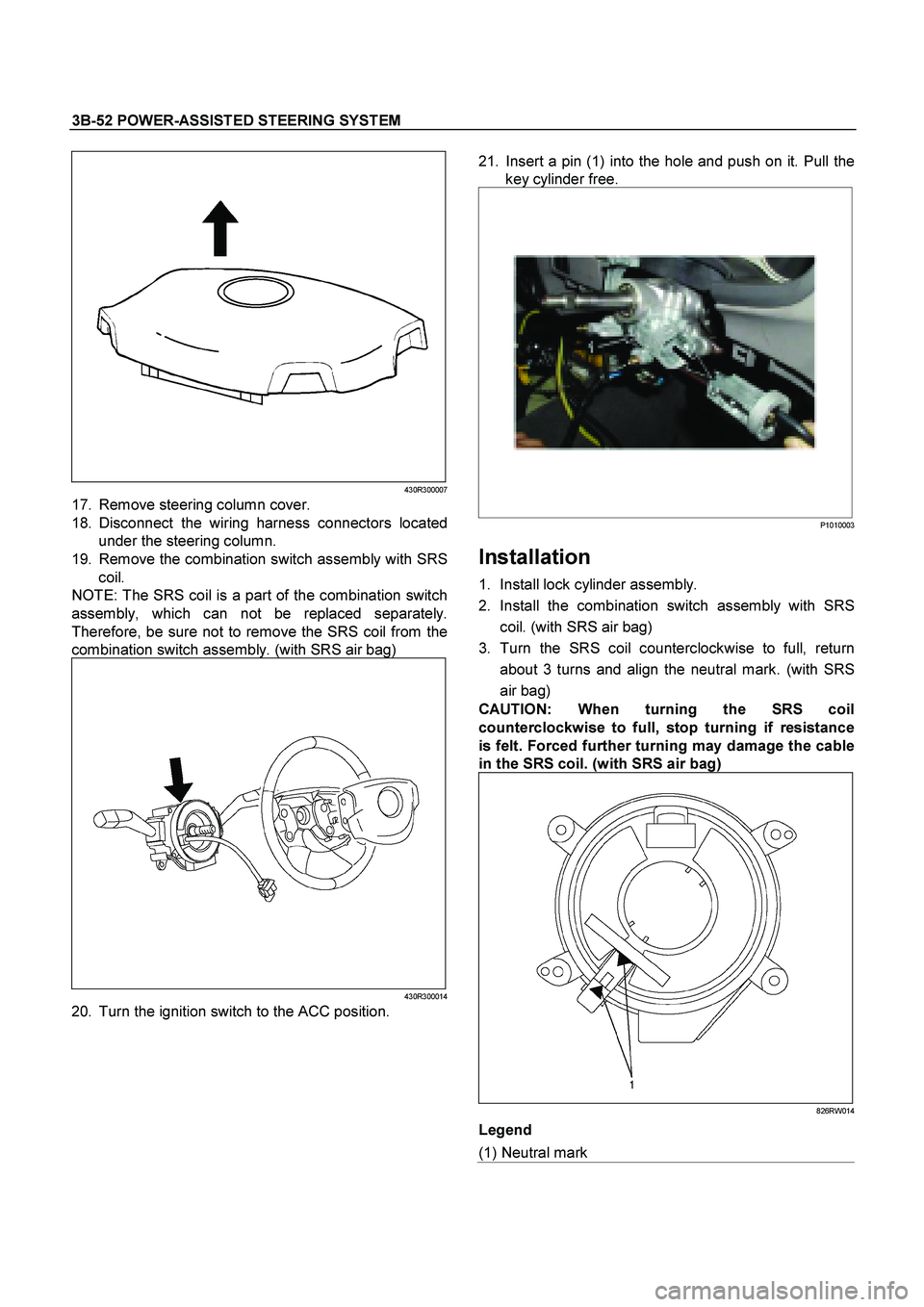
3B-52 POWER-ASSISTED STEERING SYSTEM
430R300007
17. Remove steering column cover.
18. Disconnect the wiring harness connectors located
under the steering column.
19. Remove the combination switch assembly with SRS
coil.
NOTE: The SRS coil is a part of the combination switch
assembly, which can not be replaced separately.
Therefore, be sure not to remove the SRS coil from the
combination switch assembly. (with SRS air bag)
430R300014
20. Turn the ignition switch to the ACC position.
21. Insert a pin (1) into the hole and push on it. Pull the
key cylinder free.
P1010003
Installation
1. Install lock cylinder assembly.
2. Install the combination switch assembly with SRS
coil. (with SRS air bag)
3. Turn the SRS coil counterclockwise to full, return
about 3 turns and align the neutral mark. (with SRS
air bag)
CAUTION:
When turning the SRS coil
counterclockwise to full, stop turning if resistance
is felt. Forced further turning may damage the cable
in the SRS coil.
(with SRS air bag)
826RW014
Legend
(1) Neutral mark