Page 63 of 4264
SUPPLEMENTAL RESTRAINT SYSTEM 9A-43
NOTE: Confirm SRS and Horn harness connector is
fixed by the steering wheel.
RTW33BSH000601
14.Tighten the steering wheel fixing nut to the
specified torque.
Torque: 35 N�
�� �m (3.5 kg�
�� �m/25 lb ft)
15. Install the SRS air bag assembly. (Refer to “Drive
r
Air Bag Assembly in this section)
Page 64 of 4264

9A-44 SUPPLEMENTAL RESTRAINT SYSTEM
Passenger Air Bag Assembly
Service Precautions
WARNING: SAFETY PRECAUTIONS MUST BE
FOLLOWED WHEN HANDLING A DEPLOYED AI
R
BAG ASSEMBLY. AFTER DEPLOYMENT, THE AIR
BAG ASSEMBLY SURFACE MAY CONTAIN A
SMALL AMOUNT OF SODIUM HYDROXIDE, A BY–
PRODUCT OF THE DEPLOYMENT REACTION,
THAT IS IRRITATING TO THE SKIN AND EYES.
MOST OF THE POWER ON THE AIR BAG
ASSEMBLY IS HARMLESS. AS A PRECAUTION,
WEAR GLOVES AND SAFETY GLASSES WHEN
HANDLING A DEPLOYED AIR BAG ASSEMBLY,
AND WASH YOUR HANDS WITH MILD SOAP AND
WATER AFTERWARDS.
WARNING: WHEN CARRYING A LIVE AIR BAG
ASSEMBLY, MAKE SURE THE BAG AND TRIM
COVER ARE POINTED AWAY FROM YOU. NEVE
R
CARRY AIR BAG ASSEMBLY BY THE WIRES OR
CONNECTOR ON THE UNDERSIDE OF MODULE.
IN THE CASE OF AN ACCIDENTAL DEPLOYMENT,
THE BAG WILL THEN DEPLOY WITH MINIMAL
CHANCE OF INJURY. WHEN PLACING ALIVE AI
R
BAG ASSEMBLY ON A BENCH OR OTHER
SURFACE, ALWAYS FACE BAG AND RIM COVER
UP, AWAY FROM THE SURFACE. NEVER REST A
STEERING COLUMN ASSEMBLY ON THE
STEERING WHEEL WITH THE AIR BAG
ASSEMBLY FACE DOWN AND COLUMN
VERTICAL. THIS IS NECESSARY SO THAT A FREE
SPACE IS PROVIDED TO ALLOW THE AIR BAG
ASSEMBLY TO EXPAND IN THE UNLIKELY EVENT
OF ACCIDENTAL DEPLOYMENT. OTHERWISE,
PERSONAL INJURY COULD RESULT.
WARNING: IN THE EVENT DEPLOYMENT HAS
OCCURRED, INSPECT COIL ASSEMBLY WIRE
FOR ANY SIGNS OF SCORCHING, MELTING O
R
ANY OTHER DAMAGE DUE TO EXCESSIVE HEAT.
IF THE COIL HAS BEEN DAMAGED, REPLACE IT.
Removal
1. Disable the SRS. (Refer to “Disabling the SRS”in
this section)
2. Remove glove box.
3. Remove glove box cover.
4. Remove passenger air bag assembly fixing bolts
and nuts. Universal joint is used when removing a
nut.
060R300043
060R300044
5. Remove passenger air bag assembly.
6. Disconnect passenger air bag assembly harness
connector.
Page 67 of 4264
SUPPLEMENTAL RESTRAINT SYSTEM 9A-47
Main Data and Specifications
Fastener Tightening Specification
Application N�
�� �m kg�
�� �m Ft.lb
SRS control unit 7 0.7 5
Steering wheel fixing bolt 35 3.5 25
Steering column (dash panel side fixing bolts) 20 2.0 14
Steering column (Pedal bracket fixing bolt) 20 2.0 14
Steering column (Universal joint fixing bolt) 31 3.2 23
Passenger Air Bag fixing bolt & nut 8 0.8 5.8
Pretensioner seat belt bolt 55 5.6 40
Page 70 of 4264
9A-50 SUPPLEMENTAL RESTRAINT SYSTEM
5-8840-2795-0 SRS Adapter for
Deployment Tool
901RW107
The 5-8840-2795-0 SRS Adapter for Deployment Tool
must be used with 5-8840-2468-0 SRS Deployment
Tool.
5-8521-0016-0 Steering Wheel remover
LNW28BSH003101
Page 234 of 4264
4C1-14 FRONT WHEEL DRIVE
FRONT DRIVE AXLE ASSEMBLY
Front Drive Axle Assembly and Associated Parts
RTW440LF000501
Legend
1. Propeller Shaft
2. Front Axle Case Assembly and Front Drive
Shaft Assembly
3. Washer
4. Mounting Bolt
5. Tie-rod End ; Steering Unit
6. Knuckle and Back Plate
7. Hub and Disc Assembly
8. Suspension Crossmember
Page 235 of 4264

FRONT WHEEL DRIVE 4C1-15
Removal
1. Jack up the vehicle and support it using jack stand.
2. Remove the tire and wheel.
3. Remove the stone guard.
4. Remove the brake caliper fixing bolt and hang the caliper.
Refer to Disc Brakes in Brake section.
5. Remove the antilock brake system speed sensor.
Refer to Front Wheel Speed Sensor in Brake section.
6. Remove the hub and disc assembly.
Refer to Front Hub and Disc in this section.
7. Remove the propeller shaft, refer to Front Propeller Shaft in
this section.
8. Loosen the height control arm of the torsion bar, then
remove the torsion bar from lower control arm.
Refer to Torsion Bar in Suspension section.
9. Remove the suspension crossmember.
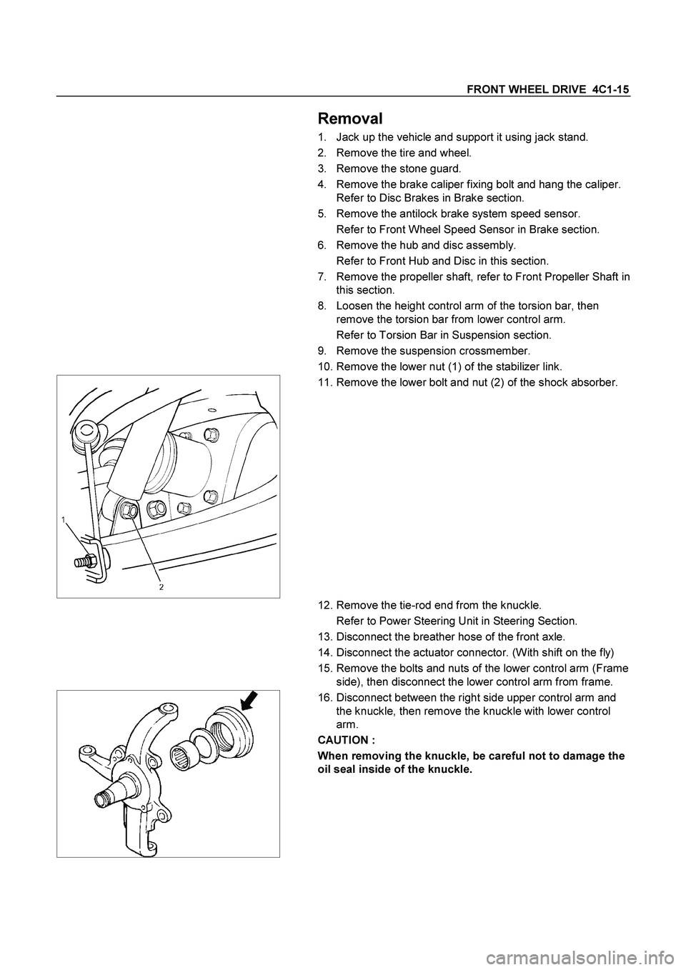
10. Remove the lower nut (1) of the stabilizer link.
11. Remove the lower bolt and nut (2) of the shock absorber.
12. Remove the tie-rod end from the knuckle.
Refer to Power Steering Unit in Steering Section.
13. Disconnect the breather hose of the front axle.
14. Disconnect the actuator connector. (With shift on the fly)
15. Remove the bolts and nuts of the lower control arm (Frame
side), then disconnect the lower control arm from frame.
16. Disconnect between the right side upper control arm and
the knuckle, then remove the knuckle with lower control
arm.
CAUTION :
When removing the knuckle, be careful not to damage the
oil seal inside of the knuckle.
Page 236 of 4264

4C1-16 FRONT WHEEL DRIVE
17. Support the differential case by the jack.
18. Remove the front axle mounting bolts and nuts, lower the
jack slowly. Remove the left side drive shaft end from the
knuckle, then lower the axle assembly from the vehicle.
CAUTION :
1. During the work, be sure that the axle assembly is
supported securly.
2. Be careful not to damage the bellows of the power
steering unit by interference.
3. Be careful not to damage the breater pipe and breater
pip bracket of the shift on the fly by interference.
Installation
1. Support the differential case by the jack.
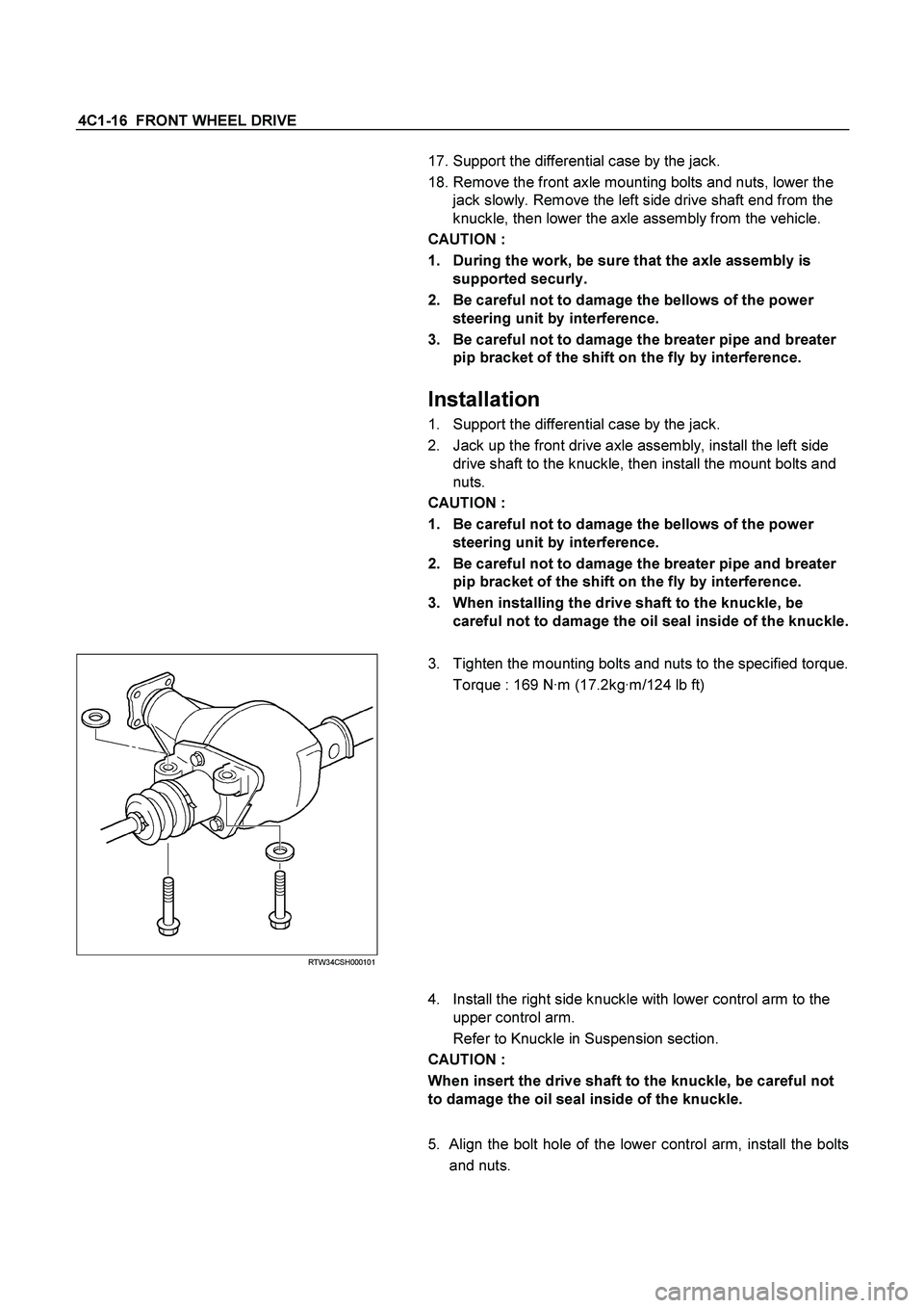
2. Jack up the front drive axle assembly, install the left side
drive shaft to the knuckle, then install the mount bolts and
nuts.
CAUTION :
1. Be careful not to damage the bellows of the power
steering unit by interference.
2. Be careful not to damage the breater pipe and breater
pip bracket of the shift on the fly by interference.
3. When installing the drive shaft to the knuckle, be
careful not to damage the oil seal inside of the knuckle.
RTW34CSH000101
3. Tighten the mounting bolts and nuts to the specified torque.
Torque : 169 N·m (17.2kg·m/124 lb ft)
4. Install the right side knuckle with lower control arm to the
upper control arm.
Refer to Knuckle in Suspension section.
CAUTION :
When insert the drive shaft to the knuckle, be careful not
to damage the oil seal inside of the knuckle.
5. Align the bolt hole of the lower control arm, install the bolts
and nuts.
Page 237 of 4264

FRONT WHEEL DRIVE 4C1-17
NOTE :
Adjust the buffer clearance before tighten the bolts and nuts of
the lower control arm.
6. Install the breather hose of the front axle.
7. Install the actuator connector of the shift on the fly. (With
shift on the fly)
8. Install the tie-rod end of the power steering unit to the
knuckle, tighten the nut to the specified torque.
Torque : 98 N·m (10.0kg·m/73 lb ft)
9. Install lower bolts and nuts of the shock absorber, tighten it
to the specified torque.
Torque : 93 N·m (9.5kg·m/69 lb ft)
10. Install lower nuts of the stabilizer link, tighten it to the
specified torque.
Torque : 50 N·m (5.1kg·m/37 lb ft)
11. Install the suspension crossmember.
12. Install the torsion bar.
Refer to Torsion Bar in Suspension section.
13. Install the front propeller shaft.
Refer to Front Propeller Shaft in this section.
14. Install the hub and disc assembly and adjust the bearing
preload.
Refer to Front Hub and Disc in this section.
15. Install the wheel speed sensor of the antilock brake
system.
16. Install the brake caliper. Tighten the bolt of the caliper
bracket to the specified torque.
Torque : 155 N·m (15.8kg·m/115 lb ft)
17. Install the stone guard.
18. Install the tire and wheel.
19. Lower the vehicle, adjust the trim height.
Refer to Trim Height Adjustment in Steering section.
20. Tighten the bolts and nuts of the lower control arm to the
specified torque.
Refer to Lower Control Arm in Suspension section.