Page 2097 of 4264

RTW46EM F000401
CIRCUIT DESCRIPTION
The “Check Engine\" lamp (MIL) should always be
illuminated and steady with")
3.5L ENGINE DRIVEABILITY AND EMISSIONS 6E -101
NO CHECK ENGINE LAMP (MIL)
RTW46EM F000401
CIRCUIT DESCRIPTION
The “Check Engine" lamp (MIL) should always be
illuminated and steady with the ignition “ON" and the
engine stopped. Ignition feed voltage is supplied to the
MIL bulb through the meter fuse. The Engine Control
Module (ECM) turns the MIL “ON" by grounding the MIL
driver circuit.
DIAGNOSTIC AIDS
An intermittent MIL may be cased by a poor connection,
rubbed-through wire insulation, or a wire broken inside
the insulation. Check for the following items:
Inspect the ECM harness and connections fo
r
improper mating, broken locks, improperly formed o
r
damaged terminals, poor terminal-to-wire connection,
and damaged harness.
If the engine runs OK, check for a faulty light bulb, an
open in the MIL driver circuit, or an open in the
instrument cluster ignition feed.
If the engine cranks but will not run, check for an
open ECM ignition or battery feed, or a poor ECM to
engine ground.
Page 2670 of 4264

Circuit Description
The check engine lamp should be illuminated and
steady for about five seconds with the ignition “ON” and
th")
6E–94 ENGINE DRIVEABILITY AND EMISSIONS
NO CHECK ENGINE LAMP (MIL)
Circuit Description
The check engine lamp should be illuminated and
steady for about five seconds with the ignition “ON” and
the engine stopped. Ignition feed voltage is supplied to
the check engine lamp bulb through the meter fuse.
The Engine Control Module (ECM) turns the check
engine lamp “ON” by grounding the check engine lamp
driver circuit.
Diagnostic Aids
An intermittent check engine lamp may be cased by a
poor connection, rubbed-through wire insulation, or awire broken inside the insulation. Check for the
following items:
Inspect the ECM harness and connections for
improper mating, broken locks, improperly formed or
damaged terminals, poor terminal-to-wire connection,
and damaged harness.
If the engine runs OK, check for a faulty light bulb, an
open in the check engine lamp driver circuit, or an
open in the instrument cluster ignition feed.
If the engine cranks but will not run, check for an
open ECM ignition or battery feed, or a poor ECM to
engine ground.
No Check Engine Lamp (MIL)
Step Action Value(s) Yes No
1 Check the “Meter” fuse (15A).
If the fuse is burnt out, repair as necessary.
Was the problem found?—Verify repair Go to Step 2
Page 3080 of 4264
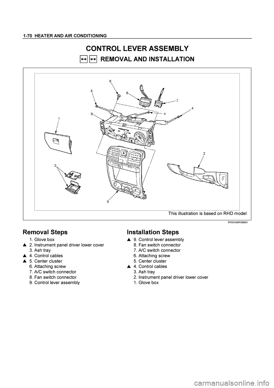
1-70 HEATER AND AIR CONDITIONING
CONTROL LEVER ASSEMBLY
REMOVAL AND INSTALLATION
This illustration is based on RHD model
RTW310MF000601
Removal Steps
1. Glove box
� 2. Instrument panel driver lower cover
3. Ash tray
� 4. Control cables
� 5. Center cluster
6. Attaching screw
7. A/C switch connector
8. Fan switch connector
9. Control lever assembly
Installation Steps
�
9. Control lever assembly
8. Fan switch connector
7. A/C switch connector
6. Attaching screw
5. Center cluster
� 4. Control cables
3. Ash tray
2. Instrument panel driver lower cover
1. Glove box
Page 3081 of 4264
HEATER AND AIR CONDITIONING 1-71
Important Operation - Removal
2. Instrument Panel Driver Lower Cover
Refer to “INSTRUMENT PANEL” in CAB section.
RTW310SH000101
4. Control Cables
Disconnect control cables at each unit side.
5. Center Cluster
Refer to “INSTRUMENT PANEL” in CAB section.
Page 3322 of 4264
 Yes No
1 Check the meter fuse for the instrument cluster
ignition feed circuit.
Is the fuse normal? �
Go to Step 3")
11A-36 IMMOBILIZER SYSTEM
NO IMMOBILIZER WARNING LAMP
Step Action Value(s) Yes No
1 Check the meter fuse for the instrument cluster
ignition feed circuit.
Is the fuse normal? �
Go to Step 3
Go to Step 2
2 Replace the fuse.
Is the action complete? �
Verify repair
Go to Step 3 �
3 1. Key position is "OFF".
2. Disconnect the meter.
3. Disconnect the engine control module (ECM).
4. Check the circuit between meter and ECM for an
open, short to round, or short to voltage.
Also, check the meter circuit for an open or short to
ground and the DLC ground circuit for an open.
Was a problem found? �
Go to Step 4
Go to Step 5
4 Repair or replace the meter circuit.
Was the action complete? �
Go to Step 5
�
5 1. Key position is "ON," engine "OFF."
2. Observe the check engine lamp.
Is the check engine lamp "ON"? �
Go to Step 6
Go to Step 7
6 Repair or replace the meter.
Was the action complete? �
Go to Step 7 �
7 1. Key position is "OFF".
2. Check the check engine lamp bulb.
Is the check engine lamp bulb normal? �
Go to Step 9
Go to Step 8
8 Replace the check engine lamp bulb.
Is the action complete? �
Verify repair
Go to Step 9 �
9 1. Key position is "OFF".
2. Connect the meter.
3. Connect the engine control module (ECM).
4. Key position is "ON".
5. Observe the check engine lamp.
Note: If a key switch is turned ON, check engine lamp
will turn on and a check engine lamp will be turned off
after a few seconds.
Is the check engine lamp "ON"? �
Verify repair
Go to Step 10
10 Replace the engine control module (ECM).
IMPORTANT: The replacement ICU must be
programmed the immobilizer data by scan tool.
Was the action complete? �
Verify repair �
Page:
< prev 1-8 9-16 17-24