Page 539 of 4264
CAB 10-31
13.Ashtray Case
� Pull out the ashtray case.
14. Center Cluster Assembly
1) Pull out the cluster at the 6 clip positions.
2) Disconnect the cigarette lighter, accessory socket,
hazard switch and clock connectors.
15. Control Lever Assembly
�
Remove the 2 fixing screws.
17.Ashtray Bracket
�
Remove the 3 fixing screws and illumination connector.
Caution:
For precautions on installation or removal of SRS-air bag
system, refer to section 9 "Supplemental Restraint System
(SRS) - AIR BAG".
21. Passenger Air Bag
�
Remove 2 fixing bolts, 2 fixing nuts and connector.
22. Side Ventilation Grille.
� Pull out the grilles and disconnect switch connecto
r
(Driver’s side).
23. Vent Duct Assembly/Defroster Nozzle Assembly
�
Refer to section 1 “HVAC” for defroster nozzle and
ventilation duct removal steps.
25. Instrument Panel
�
Remove the clip and 6 fixing bolts.
26. Cross Beam
Page 540 of 4264
10-32 CAB
INSTALLATION
This illustration is based on RHD model
RTW4A0LF001101
Installation Steps
1. Cross beam
2. Instrument panel
3. Instrument harness assembly
4. Vent duct assembly/Defroster nozzle
assembly
5. Side ventilation grille
6. Passenger air bag
7. Glove box cover
8. Passenger lower bracket
9. Meter assembly
10. Ashtray bracket
11. Storage box assembly
12. Control lever assembly
13. Center cluster assembly
14. Ashtray case
� 15. Instrument panel & Cross beam
assembly
16. Side cover
17. Front cover
18. Front pillar trim cover
19. Dash side trim cover
20. Meter cluster assembly
� 21. Steering wheel/Steering cowl
22. Driver air bag
23. Driver knee bolster assembly
24. Instrument panel driver lower cover assembly
25. Glove box
26. Front console assembly
Page 787 of 4264

ELECTRICAL-BODY AND CHASSIS 8A-129
Installation
Follow the removal procedure in the reverse order to install the
headlight.
Pay close attention to the important points mentioned in the
following paragraphs.
Connector
Be absolutely sure that the headlight connector is securely
connected.
This will prevent a contact and an open circuit.
This illustration is based on RHD model
LIGHTING SWITCH
Removal
1. Disconnect the battery ground cable.
2. Remove the steering wheel
1.
Refer to the “STEERING” Section of this manual.
3. Remove the Instrument panel lower cover
2.
4. Remove the steering column cover
3.
This illustration is based on RHD model
5. Disconnect the connector.
6. Remove the lighting switch from the steering shaft.
Installation
Follow the removal procedure in the reverse order to install the
lighting switch.
Pay close attention to the important points mentioned in the
following paragraphs.
Connector
Be absolutely sure that the lighting switch connector is securely
connected.
This will prevent a poor contact and an open circuit.
Wire Harness
Do not pinch the wire harnesses between the cluster and the
meter hood during the cluster installation procedure.
Wire damage will result.
Page 818 of 4264
8A-160 ELECTRICAL-BODY AND CHASSIS
RTU4Z0SH000901
ILLUMINATION SWITCH
RTW48ASH000601
Inspection
Check to see if there is any continuity between the terminals of
the switch.
Replace the switch when the result of inspection is found
abnormal.
RTW48ASH000501
Removal
Preparation:
Disconnect the battery ground cable.
1. Instrument panel driver lower cover assembly
Refer to the removal steps Sec.10
2. Harness switch
3. Illumination control
To remove the switch, push the lock from the back side of
the cluster assembly.
4. Remove the bulb.
Page 835 of 4264

ELECTRICAL-BODY AND CHASSIS 8A-177
REAR COMBINATION LIGHT
Back Up Light
Removal
1. Open the rear gate.
2. Remove the screws.
3. Remove the rear combination light assembly.
4. Turn the bulb
3 counterclockwise to remove it.
Installation
Follow the removal procedure in the reverse order to install the
rear combination light.
Pay close attention to the important points mentioned in the
following paragraphs.
Bulbs
Be absolutely sure that each bulb is correctly installed.
This will prevent a poor contact and an open circuit.
This illustration is based on RHD model
HAZARD WARNING FLASHER SWITCH
Removal
1. Disconnect the battery ground cable.
2. Instrument Panel Cluster Assembly
� Refer to Section 10 “BODY” for instrument panel cluste
r
assembly removal steps.
3. Hazard Warning Switch
� Disconnect the switch connector.
� To remove the switch, push the lock from the back side
of the cluster assembly.
Installation
To install, follow the removal procedure in the reverse order.
Connector
Be absolutely sure that the hazard warning flasher switch
connector is securely connected.
This will prevent a poor contact and an open circuit.
Page 920 of 4264
8A-262 ELECTRICAL-BODY AND CHASSIS
REMOVAL AND INSTALLATION
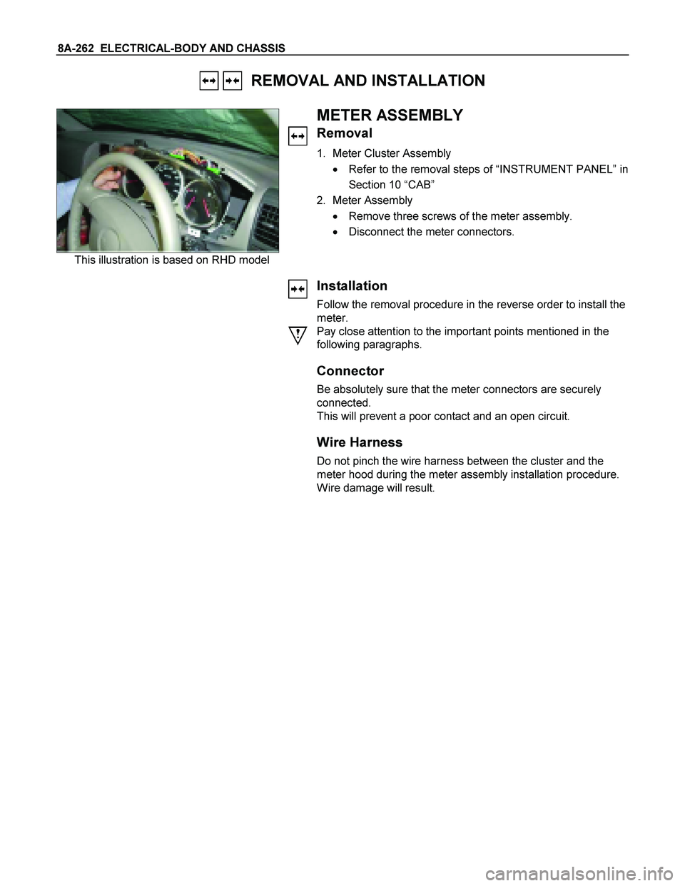
This illustration is based on RHD model
METER ASSEMBLY
Removal
1. Meter Cluster Assembly
� Refer to the removal steps of “INSTRUMENT PANEL” in
Section 10 “CAB”
2. Meter Assembly
� Remove three screws of the meter assembly.
� Disconnect the meter connectors.
Installation
Follow the removal procedure in the reverse order to install the
meter.
Pay close attention to the important points mentioned in the
following paragraphs.
Connector
Be absolutely sure that the meter connectors are securely
connected.
This will prevent a poor contact and an open circuit.
Wire Harness
Do not pinch the wire harness between the cluster and the
meter hood during the meter assembly installation procedure.
Wire damage will result.
Page 1013 of 4264
ELECTRICAL-BODY AND CHASSIS 8A-355
REMOVAL AND INSTALLATION
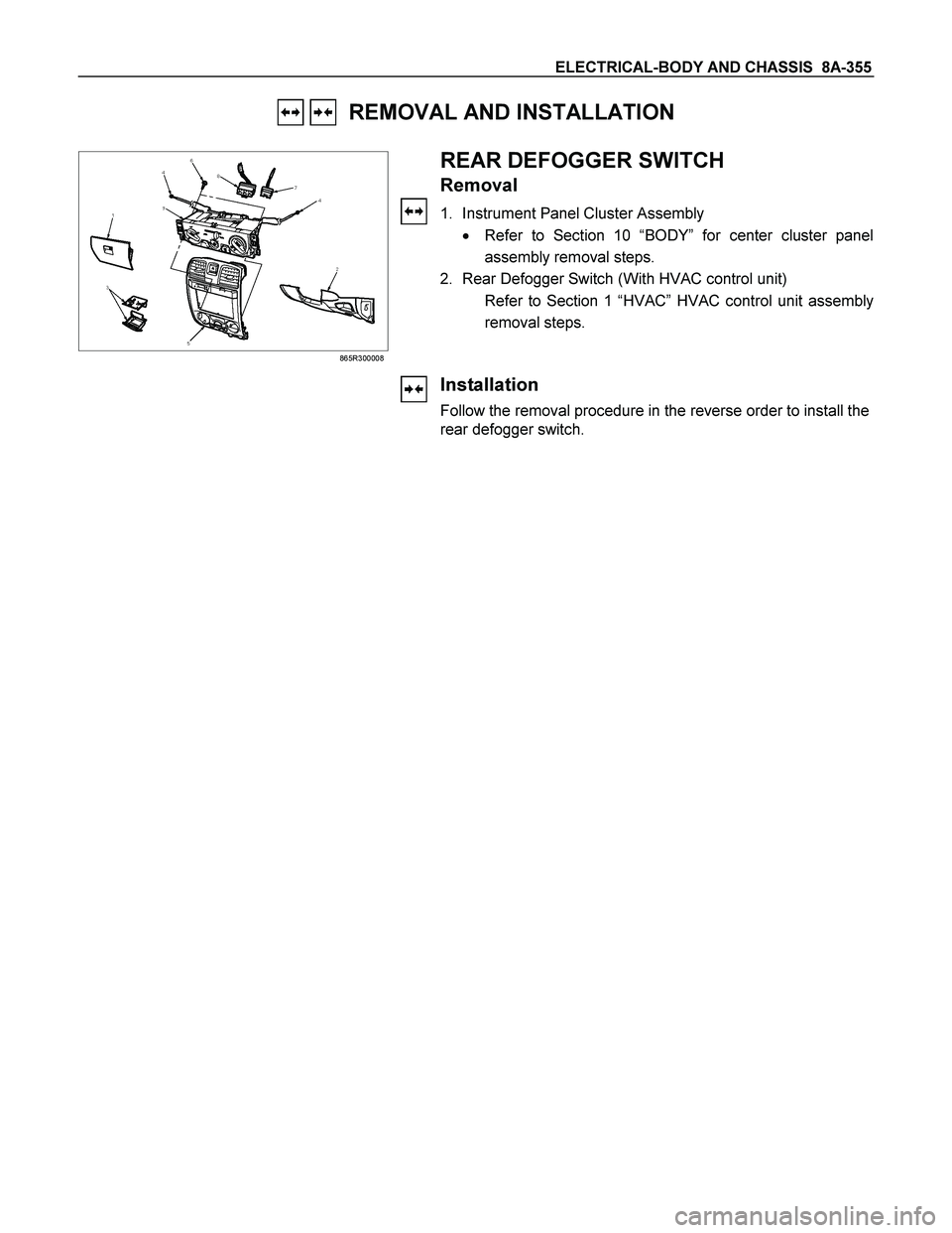
865R300008
REAR DEFOGGER SWITCH
Removal
1. Instrument Panel Cluster Assembly
� Refer to Section 10 “BODY” for center cluster panel
assembly removal steps.
2. Rear Defogger Switch (With HVAC control unit)
Refer to Section 1 “HVAC” HVAC control unit assembly
removal steps.
Installation
Follow the removal procedure in the reverse order to install the
rear defogger switch.
Page 1481 of 4264

Circuit Description
The check engine lamp should be illuminated and
steady for about five seconds with the ignition “O")
4JA1/4JH1 ENGINE DRIVEABILITY AND EMISSIONS 6E–109
NO CHECK ENGINE LAMP (MIL)
Circuit Description
The check engine lamp should be illuminated and
steady for about five seconds with the ignition “ON” and
the engine stopped. Ignition feed voltage is supplied to
the check engine lamp bulb through the meter fuse.
The Engine Control Module (ECM) turns the check
engine lamp “ON” by grounding the check engine lamp
driver circuit.
Diagnostic Aids
An intermittent check engine lamp may be cased by a
poor connection, rubbed-through wire insulation, or awire broken inside the insulation. Check for the
following items:
Inspect the ECM harness and connections for
improper mating, broken locks, improperly formed or
damaged terminals, poor terminal-to-wire connection,
and damaged harness.
If the engine runs OK, check for a faulty light bulb, an
open in the check engine lamp driver circuit, or an
open in the instrument cluster ignition feed.
If the engine cranks but will not run, check for an
open ECM ignition or battery feed, or a poor ECM to
engine ground.