Page 540 of 4264
10-32 CAB
INSTALLATION
This illustration is based on RHD model
RTW4A0LF001101
Installation Steps
1. Cross beam
2. Instrument panel
3. Instrument harness assembly
4. Vent duct assembly/Defroster nozzle
assembly
5. Side ventilation grille
6. Passenger air bag
7. Glove box cover
8. Passenger lower bracket
9. Meter assembly
10. Ashtray bracket
11. Storage box assembly
12. Control lever assembly
13. Center cluster assembly
14. Ashtray case
� 15. Instrument panel & Cross beam
assembly
16. Side cover
17. Front cover
18. Front pillar trim cover
19. Dash side trim cover
20. Meter cluster assembly
� 21. Steering wheel/Steering cowl
22. Driver air bag
23. Driver knee bolster assembly
24. Instrument panel driver lower cover assembly
25. Glove box
26. Front console assembly
Page 793 of 4264
ELECTRICAL-BODY AND CHASSIS 8A-135
LIGHTING RELAY, TAIL RELAY
Check continuity between the relay terminals.
2 - 1............................. No continuity
(When battery voltage is applied between 3 and 4)
2 - 1............................. Continuity
GLOVE BOX ILLUMINATION
Removal
1. Remove the bulb cover 1.
2. Remove the bulb
2.
Installation
To install, follow the removal steps in the reverse order.
POWER/3rd START SW
Removal
� Refer to the “Front consol” Section 10 of this manual.
1. Disconnect the battery ground cable.
2. Remove the power/3rd start switch.
3. Remove the bulb.
Installation
To install, follow the removal steps in the reverse order.
A/T LEVER LIGHT BULB
Removal
� Refer to the “Front consol” Section 10 of this manual.
1. Remove the A/T lever cover.
2. Remove the light bulb
1.
Installation
To install, follow the removal steps in the reverse order.
Page 852 of 4264

8A-194 ELECTRICAL-BODY AND CHASSIS
Installation
Follow the removal procedure in the reverse order to install the
spot light.
Pay close attention to the important points mentioned in the
following paragraphs.
Connector
Be absolutely sure that the spot light connector is securely
connected.
This will prevent a poor contact and an open circuit.
Bulb
Be absolutely sure that the spot light bulb is correctly installed.
This will prevent a poor contact and an open circuit.
RTW48ASH000801
WARNING BUZZER (ALARMER
CONTROL UNIT)
Removal
1. Disconnect the battery ground cable.
2. Remove the glove box
� Remove the screw.
3. Remove the Alarmer C/U assembly
� Remove the screw.
Installation
Follow the removal procedure in the reverse order to install the
warning buzzer.
Pay close attention to the important points mentioned in the
following paragraphs.
Connector
Be absolutely sure that the warning buzzer connector is
securely connected.
This will prevent a poor contact and an open circuit.
Page 1077 of 4264
ELECTRICAL-BODY AND CHASSIS 8A-419
No. Connector face No. Connector face
B-32
NOT USED B-44
Keyless Entry (B)
B-33
Illumination control B-45
WhiteAlarmer control unit
B-34
NOT USED B-46
Gray
Rear defogger timer
B-35
Yellow
Infrator; passenger side B-47
WhiteGlove box illumination
B-36
Yellow
Infrator; Driver side B-48
BlackG/sensor
B-37
~
B-39 NOT USED B-49
White
A/T Lever
B-40
Black
Acc socket relay B-50
WhitePower/3rd start switch
B-41
Natural
Acc socket B-51
~
B-52 NOT USED
B-42
White
Acc socket B-53
WhiteJ/B I1
B-43
Keyless Entry (A) B-54
WhiteJ/B I2
Page 3070 of 4264
1-60 HEATER AND AIR CONDITIONING
EVAPORATOR (WITH A/C)
REMOVAL AND INSTALLATION
This illustration is based on RHD model
Removal Steps
1. Glove box
2. Passenger lower bracket
3. Electronic thermostat connector
4. Drain hose
5. Refrigerant line
6. Evaporator assembly
Installation Steps
6. Evaporator assembly
5. Refrigerant line
4. Drain hose
3. Electronic thermostat connector
2. Passenger lower bracket
1. Glove box
Page 3073 of 4264
HEATER AND AIR CONDITIONING 1-63
DUCT (WITHOUT A/C)
REMOVAL AND INSTALLATION
This illustration is based on RHD model
RTW310LF001601
Removal Steps
1. Glove box
2. Passenger lower bracket
3. Evaporator assembly
Installation Steps
3. Evaporator assembly
2. Passenger lower bracket
1. Glove box
Page 3080 of 4264
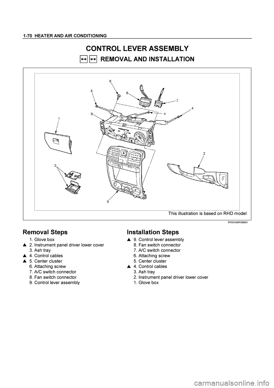
1-70 HEATER AND AIR CONDITIONING
CONTROL LEVER ASSEMBLY
REMOVAL AND INSTALLATION
This illustration is based on RHD model
RTW310MF000601
Removal Steps
1. Glove box
� 2. Instrument panel driver lower cover
3. Ash tray
� 4. Control cables
� 5. Center cluster
6. Attaching screw
7. A/C switch connector
8. Fan switch connector
9. Control lever assembly
Installation Steps
�
9. Control lever assembly
8. Fan switch connector
7. A/C switch connector
6. Attaching screw
5. Center cluster
� 4. Control cables
3. Ash tray
2. Instrument panel driver lower cover
1. Glove box
Page:
< prev 1-8 9-16 17-24


B-33
Illumination control B-45
WhiteAlarmer control unit
B-34
NOT U")

REMOVAL AND INSTALLATION
This illustration is based on RHD model
Removal Steps
1. Glove box
2. Passenger lower bracket")

REMOVAL AND INSTALLATION
This illustration is based on RHD model
RTW310LF001601
Removal Steps
1. Glove box
2. Passenger lowe")