Page 120 of 4264

9A1-50 RESTRAINT CONTROL SYSTEM
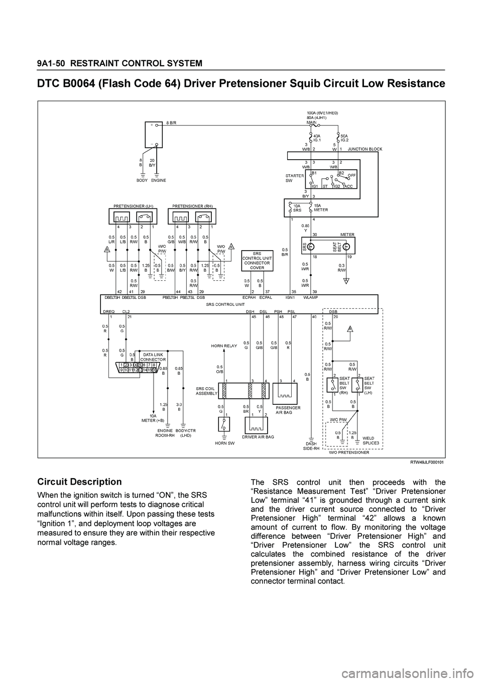
DTC B0064 (Flash Code 64) Driver Pretensioner Squib Circuit Low Resistance
RTW49JLF000101
Circuit Description
When the ignition switch is turned “ON”, the SRS
control unit will perform tests to diagnose critical
malfunctions within itself. Upon passing these tests
“Ignition 1”, and deployment loop voltages are
measured to ensure they are within their respective
normal voltage ranges.
The SRS control unit then proceeds with the
“Resistance Measurement Test” “Driver Pretensioner
Low” terminal “41” is grounded through a current sink
and the driver current source connected to “Drive
r
Pretensioner High” terminal “42” allows a known
amount of current to flow. By monitoring the voltage
difference between “Driver Pretensioner High” and
“Driver Pretensioner Low” the SRS control unit
calculates the combined resistance of the drive
r
pretensioner assembly, harness wiring circuits “Drive
r
Pretensioner High” and “Driver Pretensioner Low” and
connector terminal contact.
Page 123 of 4264

RESTRAINT CONTROL 9A1-53
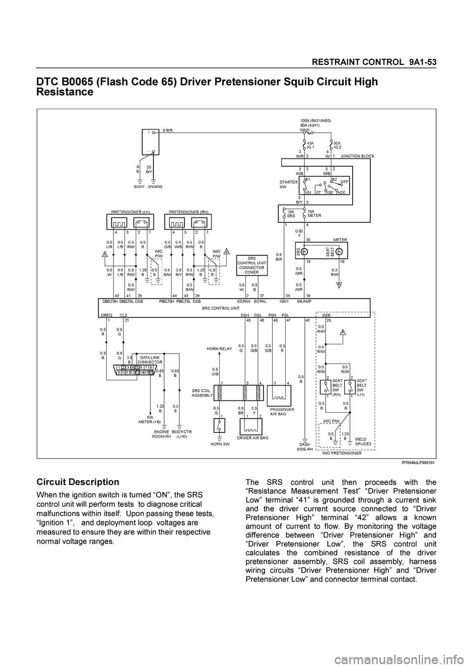
DTC B0065 (Flash Code 65) Driver Pretensioner Squib Circuit High
Resistance
RTW49JLF000101
Circuit Description
When the ignition switch is turned “ON”, the SRS
control unit will perform tests to diagnose critical
malfunctions within itself. Upon passing these tests,
“Ignition 1”, and deployment loop voltages are
measured to ensure they are within their respective
normal voltage ranges.
The SRS control unit then proceeds with the
“Resistance Measurement Test” “Driver Pretensioner
Low” terminal “41” is grounded through a current sink
and the driver current source connected to “Drive
r
Pretensioner High” terminal “42” allows a known
amount of current to flow. By monitoring the voltage
difference between “Driver Pretensioner High” and
“Driver Pretensioner Low”, the SRS control unit
calculates the combined resistance of the drive
r
pretensioner assembly, SRS coil assembly, harness
wiring circuits “Driver Pretensioner High” and “Drive
r
Pretensioner Low” and connector terminal contact.
Page 126 of 4264

9A1-56 RESTRAINT CONTROL SYSTEM
DTC B0066 (Flash Code 66) Driver Pretensioner Squib Circuit Voltage
Range/Performance
RTW49JLF000101
Circuit Description
When the ignition switch is turned “ON”, the SRS
control unit will perform tests to diagnose critical
malfunctions within itself. Upon passing these tests,
“Ignition 1”, and deployment loop voltages are
measured to ensure they are within their respective
normal voltage ranges.
The SRS control unit monitors the voltage at “Drive
r
Pretensioner Low” terminal “41” and “Passenger
Pretensioner Low” terminal “43” to detect shorts to
ground/+B in the air bag assembly circuits.
DTC Will Set When
Neither of the pretensioner is open.
“Ignition 1” is within the normal operating voltage range.
This test is run once each ignition cycle and
“Continuous Monitoring”. Once these conditions are met
and the voltage at “Driver Pretensioner Low” is out of a
specified value, DTC B0066 will set.
Action Taken
SRS control unit turns “ON” the “AIR BAG” warning
lamp and sets a diagnostic trouble code.
Page 129 of 4264

RESTRAINT CONTROL 9A1-59
DTC B0670 (Flash Code 63) Airbag Telltale Circuit Malfunction
RTW49JLF000101
Circuit Description
When the ignition switch is turned “ON”, battery voltage
is applied to the “AIR BAG” warning lamp and to the
“Ignition 1” input terminal “35”. The SRS control unit
responds by flashing the “AIR BAG” warning lamp
seven times. The SRS control unit monitors the lamp
driver output by comparing the output state at “SRS
Warning Lamp” terminal “39” to the microprocesso
r
commanded state. When “Ignition 1” is in the specified
value, and the output state does not match the
commanded state of the lamp driver for 500
milliseconds, DTC B0670 is set.
DTC Will Set When
“Ignition 1” voltage is in the specified value and the
output state at the “SRS Warning Lamp” terminal does
not match the commanded state of the lamp driver for
500 milliseconds. This test is run every 100
milliseconds during “Continuous Monitoring” tests and
once per each ignition cycle at the beginning.
Action Taken
SRS control unit attempts to turn “ON” the “AIR BAG”
warning lamp and sets a diagnostic trouble code.
DTC Will Clear When
The ignition switch is turned “OFF.”
Page 205 of 4264

REAR AXLE 4B-41
425RS066
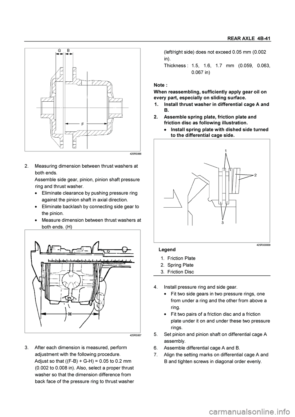
2. Measuring dimension between thrust washers at
both ends.
Assemble side gear, pinion, pinion shaft pressure
ring and thrust washer.
� Eliminate clearance by pushing pressure ring
against the pinion shaft in axial direction.
�
Eliminate backlash by connecting side gear to
the pinion.
�
Measure dimension between thrust washers at
both ends. (H)
425RS067
3. After each dimension is measured, perform
adjustment with the following procedure.
Adjust so that ((F-B) + G-H) = 0.05 to 0.2 mm
(0.002 to 0.008 in). Also, select a proper thrust
washer so that the dimension difference from
back face of the pressure ring to thrust washer
(left/right side) does not exceed 0.05 mm (0.002
in).
Thickness : 1.5, 1.6, 1.7 mm (0.059, 0.063,
0.067 in)
Note :
When reassembling, sufficiently apply gear oil on
every part, especially on sliding surface.
1. Install thrust washer in differential cage A and
B.
2. Assemble spring plate, friction plate and
friction disc as following illustration.
�
�� � Install spring plate with dished side turned
to the differential cage side.
425R300009
Legend
1. Friction Plate
2. Spring Plate
3. Friction Disc
4. Install pressure ring and side gear.
�
Fit two side gears in two pressure rings, one
from under a ring and the other from above a
ring.
�
Fit two pairs of a friction disc and a friction
plate under it on and under these two pressure
rings.
5. Set pinion and pinion shaft on differential cage A
assembly.
6. Assemble differential cage A and B.
7. Align the setting marks on differential cage A and
B and tighten screws in diagonal order evenly.
Page 276 of 4264

4C1-56 FRONT WHEEL DRIVE
Preload Adjustment
Tighten the hub nut at 29.4 N�m (3 kgf�m / 21.716 lb.ft), then
loosen the nut to the full.
Tighten the hub nut at the value given below, using a spring
scale on the wheel pin.
Bearing Preload N(lb)
New bearing and New oil seal 20 - 25 (4.4 - 5.5)
Used bearing and New oil seal 12 - 18 (2.68 - 4.0)
If the measured bearing preload is outside the specifications,
adjust it by loosening or tightening the bearing nut.
9. Lock Washer
Turn the side with larger diameter of the tapered bore to the
vehicle outer side, and attach the washer.
If the bolt holes in the lock plate are not aligned with the
corresponding holes in the nut, reverse the lock plate.
If the bolt holes are still out of alignment, turn in the nut just
enough to obtain alignment,. Screw is to be fastened tightly so
its head may come lower than the surface of the washer.
11. Snap ring, shims (4
�
�� �4 model only)
Adjust the clearance between the flange and the snap ring.
Clearance mm(in)
0 - 0.2 (0 - 0.08)
Adjust shims available
mm(in)
0.2, 0.3, 0.5, 1.0
(0.008, 0.011, 0.020, 0.039)
RTW440SH000901
13.
Bolt
Torque N�m (kgf�m/lb�ft
)
59 (6.0 / 43)
Page 285 of 4264

FRONT WHEEL DRIVE 4C1-65
Preload Adjustment
Tighten the hub nut at 29.4 N�m (3 kgf�m / 21.716 lb.ft), then
loosen the nut to the full.
Tighten the hub nut at the value given below, using a spring
scale on the wheel pin.
Bearing Preload N(lb)
New bearing and New oil seal 20 - 25 (4.4 - 5.5)
Used bearing and New oil seal 12 - 18 (2.68 - 4.0)
If the measured bearing preload is outside the specifications,
adjust it by loosening or tightening the bearing nut.
21. Lock Washer
Turn the side with larger diameter of the tapered bore to the
vehicle outer side, and attach the washer.
If the bolt holes in the lock plate are not aligned with the
corresponding holes in the nut, reverse the lock plate.
If the bolt holes are still out of alignment, turn in the nut just
enough to obtain alignment,. Screw is to be fastened tightly so
its head may come lower than the surface of the washer.
22. Body Assembly
Apply adhesive (Loctite 15 or equivalent) to the both joining
faces.
23. Snap Ring and Shims
Adjust the clearance between the free wheeling hub body and
the snap ring.
Clearance mm(in)
0 - 0.2 (0 - 0.08)
Adjust Shims Available mm(in)
0.2, 0.3, 0.5, 1.0
(0.008, 0.011, 0.020, 0.039)
24. Cover Assembly
Align stopper nails to grooves of body.
Page 338 of 4264

5A-22 BRAKE CONTROL SYSTEM
“ABS” Warning Lamp
When ABS and trouble occurs to actuate “ABS”
warning lamp, the trouble code corresponding to the
trouble is stored in the EHCU. Only ordinary brake is
available with ABS being unactuated. Even when
“ABS” warning lamp is actuated, if the starter switch is
set ON after setting it OFF once, the EHCU checks up
on the entire system and, if there is no abnormality,
judges ABS to work currently and the warning lamp is lit
normally even though the trouble code is stored.
NOTE: Illumination of the “ABS” warning lamp indicates
that anti-lock braking is no longer available. Power
assisted braking without anti-lock control is still
available.
Normal Operation
“ABS ” Warning Lamp
When the ignition is first moved from “OFF” to “RUN”,
the amber “ABS” warning lamp will turn “ON”. The
“ABS” warning lamp will turn “ON” during engine
starting and will usually stay “ON” for approximately
three seconds after the ignition switch is returned to the
“ON” position. The warning lamp should remain “OFF”
at all other times.
Brake (EBD) Warning Lamp
825L300001
Vehicles equipped with the EBD (Electronic Brake-force
Distribution) System have an have “Brake” warning
lamp in the instrument panel.
If ABS warning lamp and Brake warning lamp are turn
"ON", then EBD is failed. ( Parking brake switch is
"OFF")
In the following conditions, EBD warning lamp is "ON".
Starter switch is "ON", engine "OFF".
( Parking brake switch is "OFF")
If engine is started, then EBD warning lamp is "OFF".
( Parking brake switch is "OFF")