2004 ISUZU TF SERIES display
[x] Cancel search: displayPage 2667 of 4264
ENGINE DRIVEABILITY AND EMISSIONS 6E–91
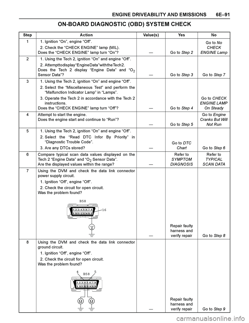
ON-BOARD DIAGNOSTIC (OBD) SYSTEM CHECK
Step Action Value(s) Yes No
1 1. Ignition “On”, engine “Off”.
2. Check the “CHECK ENGINE” lamp (MIL).
Does the “CHECK ENGINE” lamp turn “On”?—Go to Step 2Go to No
CHECK
ENGINE Lamp
2 1. Using the Tech 2, ignition “On” and engine “Off”.
2. Attempt to display “Engine Data” w i t h t h e T e c h 2 .
Does the Tech 2 display “Engine Data” and “O
2Sensor Data”? —Go to Step 3Go to Step 7
3 1. Using the Tech 2, ignition “On” and engine “Off”.
2. Select the “Miscellaneous Test” and perform the
“Malfunction Indicator Lamp” in “Lamps”.
3. Operate the Tech 2 in accordance with the Tech 2
instructions.
Does the “CHECK ENGINE” lamp turn “Off”? —Go to Step 4Go to CHECK
ENGINE LAMP
On Steady
4 Attempt to start the engine.
Does the engine start and continue to “Run”?
—Go to Step 5Go to Engine
Cranks But Will
Not Run
5 1. Using the Tech 2, ignition “On” and engine “Off”.
2. Select the “Read DTC Infor By Priority” in
“Diagnostic Trouble Code”.
3. Are any DTCs stored?—Go to DTC
ChartGo to Step 6
6 Compare typical scan data values displayed on the
Te c h 2 “Engine Data” and “O
2 Sensor Data”.
Are the displayed values within the range?—Refer to
SYMPTOM
DIAGNOSISRefer to
TYPICAL
SCAN DATA
7 Using the DVM and check the data link connector
power supply circuit.
1. Ignition “Off”, engine “Off”.
2. Check the circuit for open circuit.
Was the problem found?
—Repair faulty
harness and
verify repair Go to Step 8
8 Using the DVM and check the data link connector
ground circuit.
1. Ignition “Off”, engine “Off”.
2. Check the circuit for open circuit.
Was the problem found?
—Repair faulty
harness and
verify repair Go to Step 9
V
16
B58
5 4B58
Page 2674 of 4264
6E–98 ENGINE DRIVEABILITY AND EMISSIONS
FUEL METERING SYSTEM CHECK
Some failures of the fuel metering system will result in
an “Engine Cranks But Will Not Run” symptom. If this
condition ex ists, refer to the Cranks But Will Not Run
chart. This chart will determine if the problem is caused
by the ignition system, the ECM, or the fuel pump
electrical circuit.
Refer to Fuel System Electrical Test for the fuel system
wiring schematic.
If there is a fuel delivery problem, refer to Fuel System
Diagnosis, which diagnoses the fuel injectors, the fuel
pressure regulator, and the fuel pump.
Followings are applicable to the vehicles with
closed Loop System:
If a malfunction occurs in the fuel metering system, it
usually results in either a rich HO2S signal or a lean
HO2S signal. This condition is indicated by the HO2S
voltage, which causes the ECM to change the fuel
calculation (fuel injector pulse width) based on the
HO2S reading. Changes made to the fuel calculation
will be indicated by a change in the long term fuel trim
values which can be monitored with a Scan Tool. Ideal
long term fuel trim values are around 0%; for a lean
HO2S signal, the ECM will add fuel, resulting in a fuel
trim value above 0%. Some variations in fuel trim values
are normal because all engines are not ex actly the
same. If the evaporative emission canister purge is 02
status may be rich condition. 02 status indicates the
lean condition, refer to DTC P1171 for items which can
cause a lean HO2S signal.
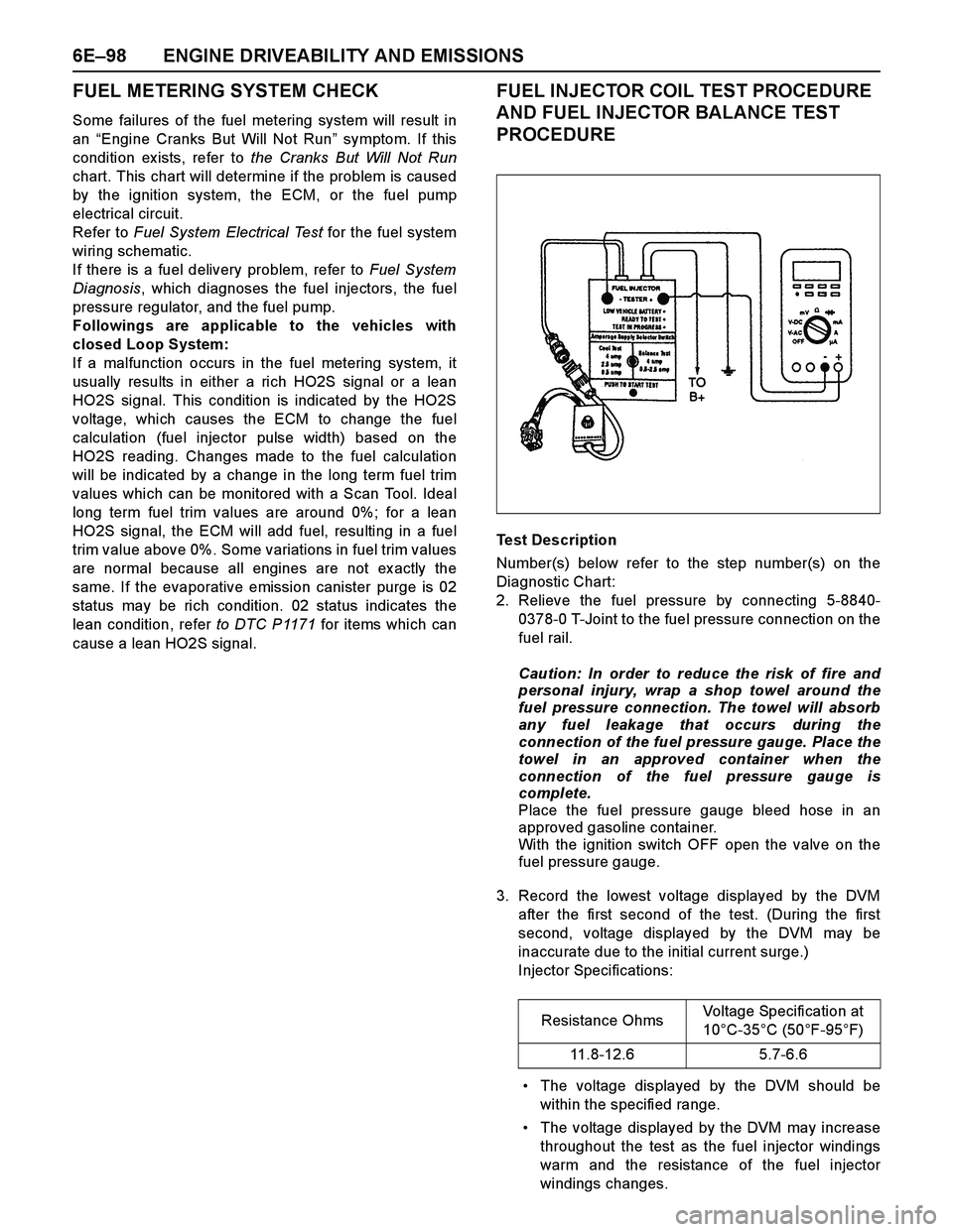
FUEL INJECTOR COIL TEST PROCEDURE
AND FUEL INJECTOR BALANCE TEST
PROCEDURE
Test Description
Number(s) below refer to the step number(s) on the
Diagnostic Chart:
2. Relieve the fuel pressure by connecting 5-8840-
0378-0 T-Joint to the fuel pressure connection on the
fuel rail.
Caution: In order to reduce the risk of fire and
personal injury, wrap a shop towel around the
fuel pressure connection. The towel will absorb
any fuel leakage that occurs during the
connection of the fuel pressure gauge. Place the
towel in an approved container when the
connection of the fuel pressure gauge is
complete.
Place the fuel pressure gauge bleed hose in an
approved gasoline container.
With the ignition switch OFF open the valve on the
fuel pressure gauge.
3. Record the lowest voltage displayed by the DVM
after the first second of the test. (During the first
second, voltage displayed by the DVM may be
inaccurate due to the initial current surge.)
Injector Specifications:
The voltage displayed by the DVM should be
within the specified range.
The voltage displayed by the DVM may increase
throughout the test as the fuel injector windings
warm and the resistance of the fuel injector
windings changes.Resistance OhmsVoltage Specification at
10°C-35°C (50°F-95°F)
11.8-12.6 5.7-6.6
Page 2696 of 4264

6E–120 ENGINE DRIVEABILITY AND EMISSIONS
connectors for backed-out terminals, improper
mating, broken locks, improperly formed or damaged
terminals, and poor terminal-to-wire connection.
If these codes are also set, it could indicate a
problem with the 5 Volt reference circuit.
Damaged harness - Inspect the wiring harness fordamage, short to ground, short to battery positive,
and open circuit. If the harness appears to be OK,
observe the MAP display on the Tech 2 while moving
connectors and wiring harnesses related to the
sensor. A change in the display will indicate the
location of the fault.
Diagnostic Trouble Code (DTC) P0107
Manifold Absolute Pressure Circuit Low Input
Step A ction Value(s) Yes No
1 Was the “On-Board Diagnostic (OBD) System Check”
performed?
—Go to Step 2Go to On Board
Diagnostic
(OBD) System
Check
2 1. Connect the Tech 2.
2. Review and record the failure information.
3. Select “F0: Read DTC Infor By Priority” in “F0:
Diagnostic Trouble Code”.
Is the DTC P0107 stored as “Present Failure”?—Go to Step 3Refer to
Diagnostic Aids
and Go to Step
3
3 1. Using the Tech2, ignition “On” and engine “Off”.
2. Select “Clear DTC Information” with the Tech2 and
clear the DTC information.
3. Operate the vehicle and monitor the “F5: Failed
This Ignition” in “F2: DTC Information”.
Was the DTC P0107 stored in this ignition cycle?—Go to Step 4Refer to
Diagnostic Aids
and Go to Step
4
4 Check for poor/faulty connection at the MAP sensor or
ECM connector. If a poor/faulty connection is found,
repair as necessary.
Was the problem found?
—Verify repair Go to Step 5
5 Visually check the MAP.
Was the problem found? —Go to Step 9 Go to Step 6
6 Using the DVM and check the MAP sensor power
supply circuit.
1. Ignition “On”, engine “Off”.
2. Disconnect the MAP sensor connector.
3. Check the circuit for open or short to ground
circuit.
Was the DVM indicated specified value?
Approx imately
5.0V Go to Step 8Go to Step 7
16
31 24E85 E60(J1)
V
E85
3
Page 2700 of 4264
6E–124 ENGINE DRIVEABILITY AND EMISSIONS
Diagnostic Aids
Check for the following conditions:
Poor connection at ECM - Inspect harness
connectors for backed-out terminals, improper
mating, broken locks, improperly formed or damaged
terminals, and poor terminal-to-wire connection.
If these codes are also set, it could indicate aproblem with the 5 Volt reference circuit.
Damaged harness - Inspect the wiring harness for
damage; an open circuit, a short to ground, or a short
to voltage. If the harness appears to be OK, observe
the MAP display on the Tech 2 while moving
connectors and wiring harnesses related to the
sensor. A change in the display will indicate the
location of the fault.
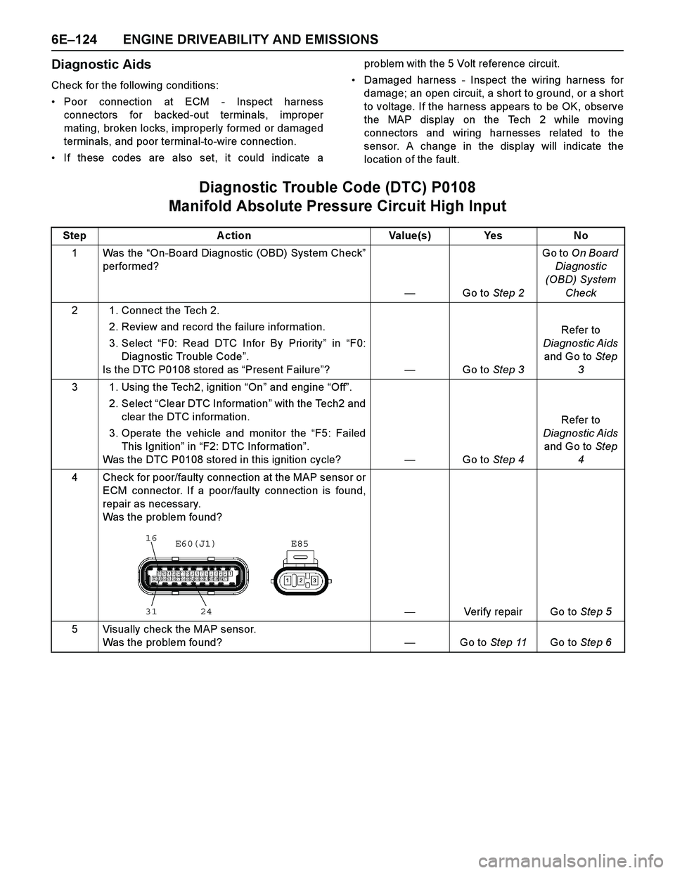
Diagnostic Trouble Code (DTC) P0108
Manifold Absolute Pressure Circuit High Input
Step Action Value(s) Yes No
1Was the “On-Board Diagnostic (OBD) System Check”
performed?
—Go to Step 2Go to On Board
Diagnostic
(OBD) System
Check
2 1. Connect the Tech 2.
2. Review and record the failure information.
3. Select “F0: Read DTC Infor By Priority” in “F0:
Diagnostic Trouble Code”.
Is the DTC P0108 stored as “Present Failure”?—Go to Step 3Refer to
Diagnostic Aids
and Go to Step
3
3 1. Using the Tech2, ignition “On” and engine “Off”.
2. Select “Clear DTC Information” with the Tech2 and
clear the DTC information.
3. Operate the vehicle and monitor the “F5: Failed
This Ignition” in “F2: DTC Information”.
Was the DTC P0108 stored in this ignition cycle?—Go to Step 4Refer to
Diagnostic Aids
and Go to Step
4
4 Check for poor/faulty connection at the MAP sensor or
ECM connector. If a poor/faulty connection is found,
repair as necessary.
Was the problem found?
—Verify repair Go to Step 5
5 Visually check the MAP sensor.
Was the problem found?—Go to Step 11Go to Step 6
16
31 24E85 E60(J1)
Page 2704 of 4264
6E–128 ENGINE DRIVEABILITY AND EMISSIONS
circuit. If the harness appears to be OK, observe the
IAT display on the Tech 2 while moving connectors
and wiring harnesses related to the IAT sensor. Achange in the IAT display will indicate the location of
the fault.
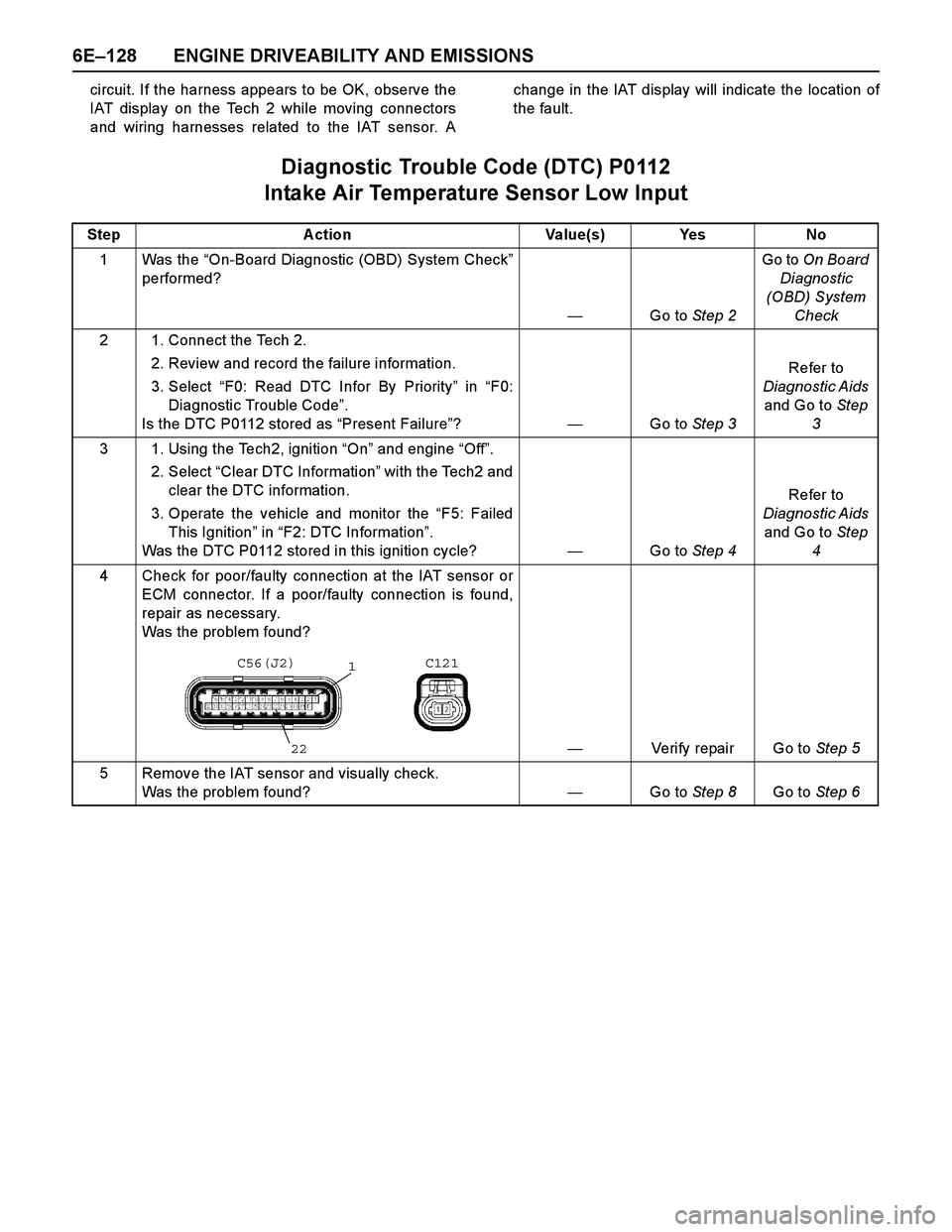
Diagnostic Trouble Code (DTC) P0112
Intake Air Temperature Sensor Low Input
Step A ction Value(s) Yes No
1 Was the “On-Board Diagnostic (OBD) System Check”
performed?
—Go to Step 2Go to On Board
Diagnostic
(OBD) System
Check
2 1. Connect the Tech 2.
2. Review and record the failure information.
3. Select “F0: Read DTC Infor By Priority” in “F0:
Diagnostic Trouble Code”.
Is the DTC P0112 stored as “Present Failure”?—Go to Step 3Refer to
Diagnostic Aids
and Go to Step
3
3 1. Using the Tech2, ignition “On” and engine “Off”.
2. Select “Clear DTC Information” with the Tech2 and
clear the DTC information.
3. Operate the vehicle and monitor the “F5: Failed
This Ignition” in “F2: DTC Information”.
Was the DTC P0112 stored in this ignition cycle?—Go to Step 4Refer to
Diagnostic Aids
and Go to Step
4
4 Check for poor/faulty connection at the IAT sensor or
ECM connector. If a poor/faulty connection is found,
repair as necessary.
Was the problem found?
—Verify repair Go to Step 5
5 Remove the IAT sensor and visually check.
Was the problem found? —Go to Step 8Go to Step 6
C56(J2) C121
1
22
Page 2708 of 4264

6E–132 ENGINE DRIVEABILITY AND EMISSIONS
terminals, and poor terminal-to-wire connection.
Damaged harness - Inspect the wiring harness for
damage, short to ground, short to battery positive,
and open circuit. If the harness appears to be OK,observe the IAT display on the Tech 2 while moving
connectors and wiring harnesses related to the IAT
sensor. A change in the IAT display will indicate the
location of the fault.
Diagnostic Trouble Code (DTC) P0113
Intake Air Temperature Sensor High Input
Step A ction Value(s) Yes No
1 Was the “On-Board Diagnostic (OBD) System Check”
performed?
—Go to Step 2Go to On Board
Diagnostic
(OBD) System
Check
2 1. Connect the Tech 2.
2. Review and record the failure information.
3. Select “F0: Read DTC Infor By Priority” in “F0:
Diagnostic Trouble Code”.
Is the DTC P0113 stored as “Present Failure”?—Go to Step 3Refer to
Diagnostic Aids
and Go to Step
3
3 1. Using the Tech2, ignition “On” and engine “Off”.
2. Select “Clear DTC Information” with the Tech2 and
clear the DTC information.
3. Operate the vehicle and monitor the “F5: Failed
This Ignition” in “F2: DTC Information”.
Was the DTC P0113 stored in this ignition cycle?—Go to Step 4Refer to
Diagnostic Aids
and Go to Step
4
4 Check for poor/faulty connection at the IAT sensor or
ECM connector. If a poor/faulty connection is found,
repair as necessary.
Was the problem found?
—Verify repair Go to Step 5
5 Visually check the IAT sensor.
Was the problem found? —Go to Step 12Go to Step 6
C56(J2) C121
1
22
Page 2712 of 4264
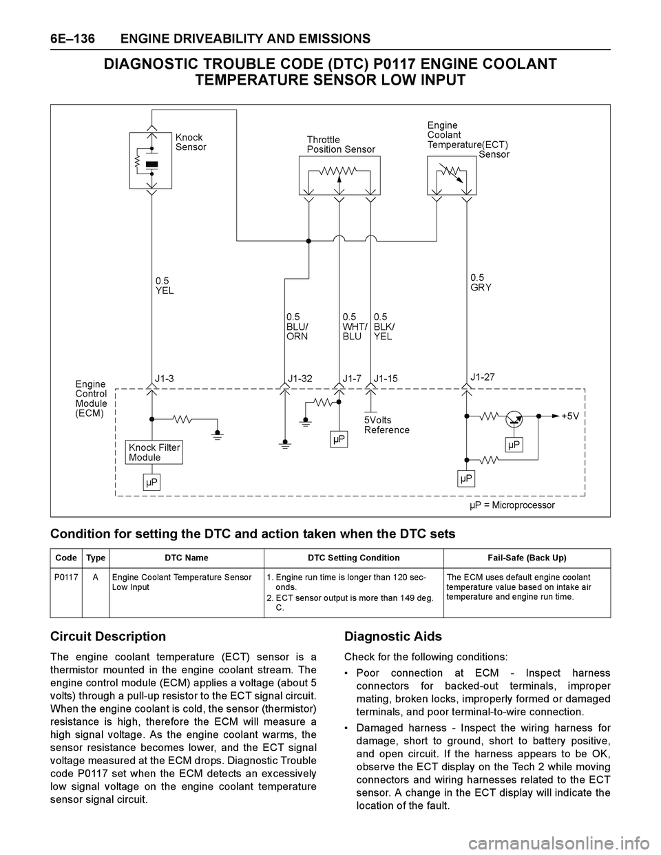
6E–136 ENGINE DRIVEABILITY AND EMISSIONS
DIAGNOSTIC TROUBLE CODE (DTC) P0117 ENGINE COOLANT
TEMPERATURE SENSOR LOW INPUT
Condition for setting the DTC and action taken when the DTC sets
Circuit Description
The engine coolant temperature (ECT) sensor is a
thermistor mounted in the engine coolant stream. The
engine control module (ECM) applies a voltage (about 5
volts) through a pull-up resistor to the ECT signal circuit.
When the engine coolant is cold, the sensor (thermistor)
resistance is high, therefore the ECM will measure a
high signal voltage. As the engine coolant warms, the
sensor resistance becomes lower, and the ECT signal
voltage measured at the ECM drops. Diagnostic Trouble
code P0117 set when the ECM detects an ex cessively
low signal voltage on the engine coolant temperature
sensor signal circuit.
Diagnostic Aids
Check for the following conditions:
Poor connection at ECM - Inspect harness
connectors for backed-out terminals, improper
mating, broken locks, improperly formed or damaged
terminals, and poor terminal-to-wire connection.
Damaged harness - Inspect the wiring harness for
damage, short to ground, short to battery positive,
and open circuit. If the harness appears to be OK,
observe the ECT display on the Tech 2 while moving
connectors and wiring harnesses related to the ECT
sensor. A change in the ECT display will indicate the
location of the fault.
Code Type DTC Name DTC Setting Condition Fail-Safe (Back Up)
P0117 A Engine Coolant Temperature Sensor
Lo w Input1. Engine run time is longer than 120 sec-
onds.
2. ECT sensor output is more than 149 deg.
C. The ECM uses default engine coolant
temperature value based on intake air
temperature and engine run time.
Page 2715 of 4264
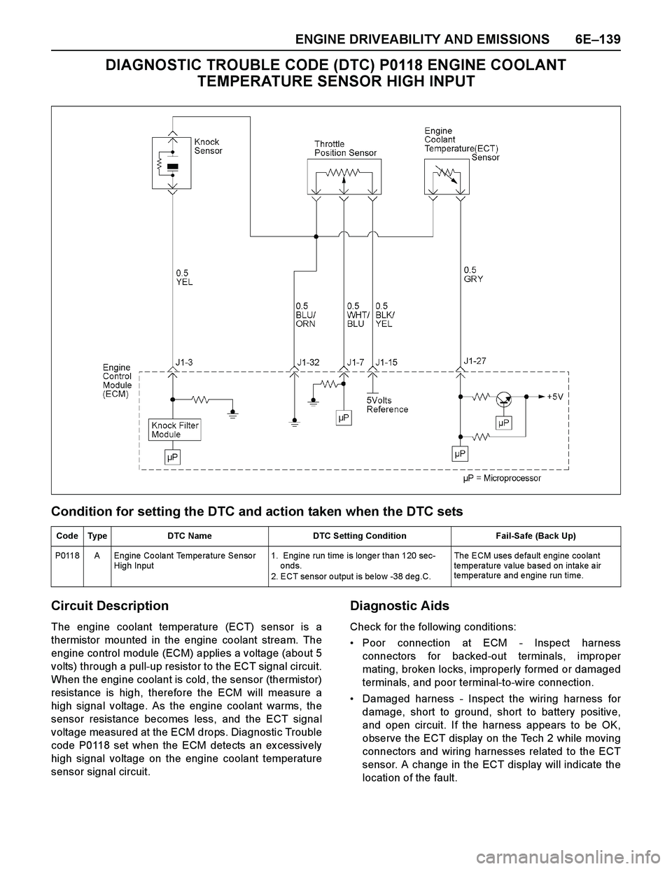
ENGINE DRIVEABILITY AND EMISSIONS 6E–139
DIAGNOSTIC TROUBLE CODE (DTC) P0118 ENGINE COOLANT
TEMPERATURE SENSOR HIGH INPUT
Condition for setting the DTC and action taken when the DTC sets
Circuit Description
The engine coolant temperature (ECT) sensor is a
thermistor mounted in the engine coolant stream. The
engine control module (ECM) applies a voltage (about 5
volts) through a pull-up resistor to the ECT signal circuit.
When the engine coolant is cold, the sensor (thermistor)
resistance is high, therefore the ECM will measure a
high signal voltage. As the engine coolant warms, the
sensor resistance becomes less, and the ECT signal
voltage measured at the ECM drops. Diagnostic Trouble
code P0118 set when the ECM detects an ex cessively
high signal voltage on the engine coolant temperature
sensor signal circuit.
Diagnostic Aids
Check for the following conditions:
Poor connection at ECM - Inspect harness
connectors for backed-out terminals, improper
mating, broken locks, improperly formed or damaged
terminals, and poor terminal-to-wire connection.
Damaged harness - Inspect the wiring harness for
damage, short to ground, short to battery positive,
and open circuit. If the harness appears to be OK,
observe the ECT display on the Tech 2 while moving
connectors and wiring harnesses related to the ECT
sensor. A change in the ECT display will indicate the
location of the fault.
Code Type DTC Name DTC Setting Condition Fail-Safe (Back Up)
P0118 A Engine Coolant Temperature Sensor
High Input1. Engine run time is longer than 120 sec-
onds.
2. ECT sensor output is below -38 deg.C. The ECM uses default engine coolant
temperature value based on intake air
temperature and engine run time.