Page 2834 of 4264

6E–258 ENGINE DRIVEABILITY AND EMISSIONS
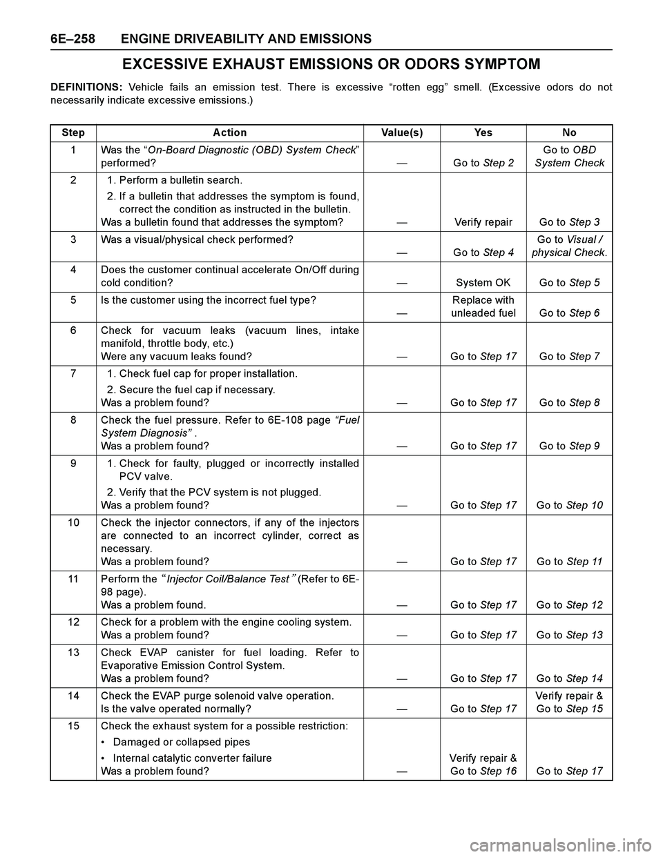
EXCESSIVE EXHAUST EMISSIONS OR ODORS SYMPTOM
DEFINITIONS: Vehicle fails an emission test. There is ex cessive “rotten egg” smell. (Ex cessive odors do not
necessarily indicate ex cessive emissions.)
Step Action Value(s) Yes No
1Was the “On-Board Diagnostic (OBD) System Check”
performed?—Go to Step 2Go to OBD
System Check
2 1. Perform a bulletin search.
2. If a bulletin that addresses the symptom is found,
correct the condition as instructed in the bulletin.
Was a bulletin found that addresses the symptom?—Verify repair Go to Step 3
3 Was a visual/physical check performed?
—Go to Step 4Go to Visual /
physical Check.
4 Does the customer continual accelerate On/Off during
cold condition?—System OK Go to Step 5
5 Is the customer using the incorrect fuel type?
—Replace with
unleaded fuel Go to Step 6
6 Check for vacuum leaks (vacuum lines, intake
manifold, throttle body, etc.)
Were any vacuum leaks found?—Go to Step 17Go to Step 7
7 1. Check fuel cap for proper installation.
2. Secure the fuel cap if necessary.
Was a problem found?—Go to Step 17Go to Step 8
8 Check the fuel pressure. Refer to 6E-108 page “Fuel
System Diagnosis” .
Was a problem found?—Go to Step 17Go to Step 9
9 1. Check for faulty, plugged or incorrectly installed
PCV valve.
2. Verify that the PCV system is not plugged.
Was a problem found? —Go to Step 17Go to Step 10
10 Check the injector connectors, if any of the injectors
are connected to an incorrect cylinder, correct as
necessary.
Was a problem found?—Go to Step 17Go to Step 11
11 Perform the �Injector Coil/Balance Test� (Refer to 6E-
98 page).
Was a problem found.—Go to Step 17Go to Step 12
12 Check for a problem with the engine cooling system.
Was a problem found?—Go to Step 17Go to Step 13
13 Check EVAP canister for fuel loading. Refer to
Evaporative Emission Control System.
Was a problem found?—Go to Step 17Go to Step 14
14 Check the EVAP purge solenoid valve operation.
Is the valve operated normally?—Go to Step 17Veri fy repai r &
Go to Step 15
15 Check the ex haust system for a possible restriction:
Damaged or collapsed pipes
Internal catalytic converter failure
Was a problem found?—Verify repair &
Go to Step 16Go to Step 17
Page 2847 of 4264

ENGINE DRIVEABILITY AND EMISSIONS 6E–271
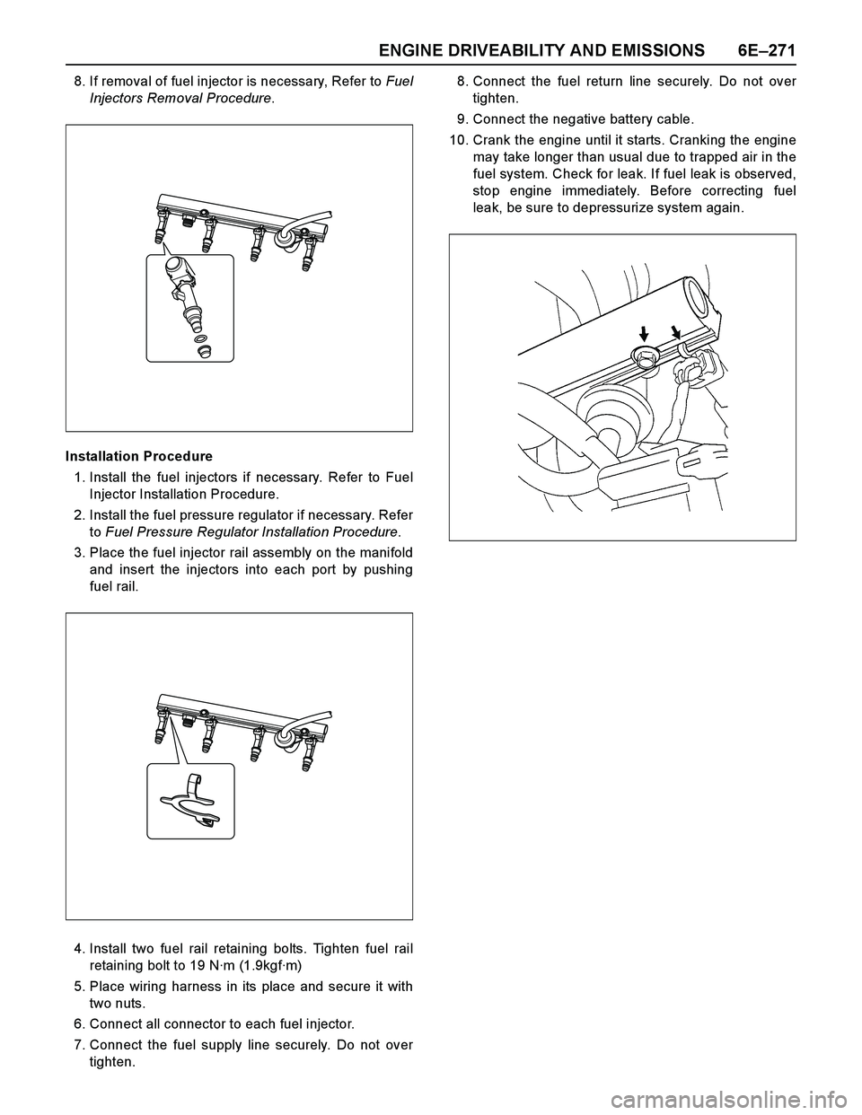
8. If removal of fuel injector is necessary, Refer to Fuel
Injectors Removal Procedure.
Installation Procedure
1. Install the fuel injectors if necessary. Refer to Fuel
Injector Installation Procedure.
2. Install the fuel pressure regulator if necessary. Refer
to Fuel Pressure Regulator Installation Procedure.
3. Place the fuel injector rail assembly on the manifold
and insert the injectors into each port by pushing
fuel rail.
4. Install two fuel rail retaining bolts. Tighten fuel rail
retaining bolt to 19 N·m (1.9kgf·m)
5. Place wiring harness in its place and secure it with
two nuts.
6. Connect all connector to each fuel injector.
7. Connect the fuel supply line securely. Do not over
tighten.8. Connect the fuel return line securely. Do not over
tighten.
9. Connect the negative battery cable.
10. Crank the engine until it starts. Cranking the engine
may take longer than usual due to trapped air in the
fuel system. Check for leak. If fuel leak is observed,
stop engine immediately. Before correcting fuel
leak, be sure to depressurize system again.
Page 2938 of 4264
2B-6 SHEET METAL
Important Operations - Installation
4. Control Cable
Reroute the control cable to its original position, and check and
see if the lock assembly and control lever work normally.
2. Engine Hood Lock Assembly
Adjustment
1) Install the engine hood lock assembly (4) and temporaril
y
tighten the bolts securing it.
2) Close the hood.
3) Position the hood so that the stepped portion between the
hood (1) and the fender (2) is precisely 1.5 mm (0.06 in)
high.
4) Final tighten the bolts securing the engine hood lock
assembly.
5) Turn the buffers (3) counterclockwise until the stepped
portion between the hood and the fender disappears.
6) Tighten the hood lock assembly fixing bolts to the specified
torque.
Torque N�
m(kgf�
m/lb�
in)
10 (1.0
/ 87)
Page 3037 of 4264
HEATER AND AIR CONDITIONING 1-27
REPAIR OF REFRIGERANT LEAKS
Refrigerant Line Connections
RTW410SH000101
Install new O-ring, if required. When disconnecting or
connecting lines, use two wrenches to prevent the connecting
portion from twisting or becoming damaged.
When connecting the refrigerant line at the block joint, securely
insert the projecting portion of the joint portion into the
connecting hole on the unit side and secure with a bolt.
Apply specified compressor oil to the O-rings prior to
connecting.
CAUTION:
Compressor (PAG) oil to be used varies according to
compressor model. Be sure to apply oil specified for the
model of compressor.
O-rings must be closely aligned with raised portion of
refrigerant line.
Page 3093 of 4264

HEATER AND AIR CONDITIONING 1-83
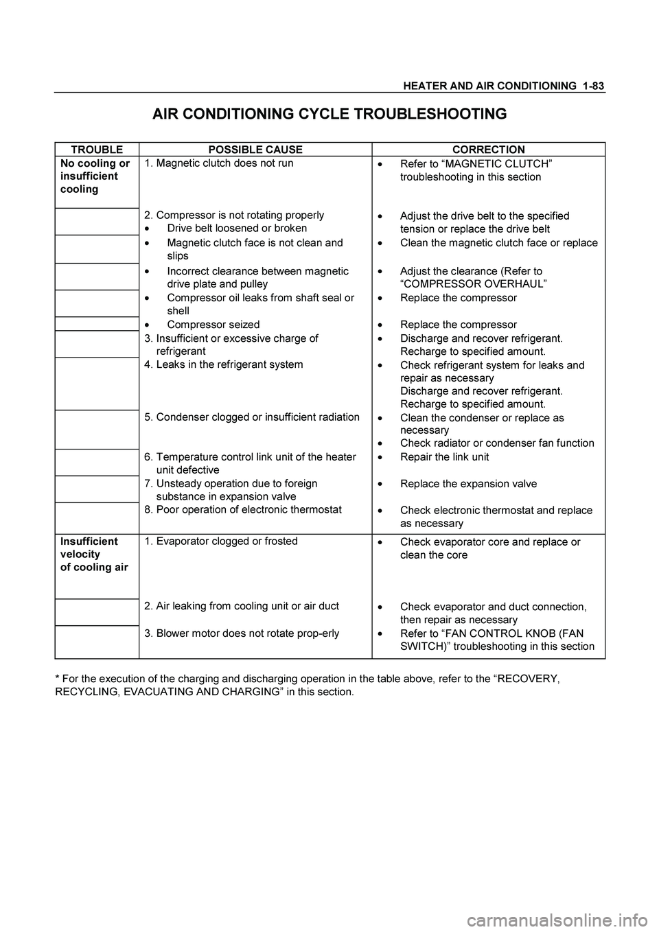
AIR CONDITIONING CYCLE TROUBLESHOOTING
TROUBLE POSSIBLE CAUSE CORRECTION
No cooling or
insufficient
cooling
1. Magnetic clutch does not run
��
Refer to “MAGNETIC CLUTCH”
troubleshooting in this section
2. Compressor is not rotating properly
��Drive belt loosened or broken ��
Adjust the drive belt to the specified
tension or replace the drive belt
��Magnetic clutch face is not clean and
slips ��Clean the magnetic clutch face or replace
��
Incorrect clearance between magnetic
drive plate and pulley ��
Adjust the clearance (Refer to
“COMPRESSOR OVERHAUL”
��
Compressor oil leaks from shaft seal or
shell ��
Replace the compressor
��
Compressor seized ��
Replace the compressor
3. Insufficient or excessive charge of
refrigerant ��
Discharge and recover refrigerant.
Recharge to specified amount.
4. Leaks in the refrigerant system
��
Check refrigerant system for leaks and
repair as necessary
Discharge and recover refrigerant.
Recharge to specified amount.
5. Condenser clogged or insufficient radiation
��Clean the condenser or replace as
necessary
��
Check radiator or condenser fan function
6. Temperature control link unit of the heater
unit defective ��
Repair the link unit
7. Unsteady operation due to foreign
substance in expansion valve ��
Replace the expansion valve
8. Poor operation of electronic thermostat
��
Check electronic thermostat and replace
as necessary
Insufficient
velocity
of cooling air
1. Evaporator clogged or frosted
��
Check evaporator core and replace or
clean the core
2. Air leaking from cooling unit or air duct
��Check evaporator and duct connection,
then repair as necessary
3. Blower motor does not rotate prop-erly
��
Refer to “FAN CONTROL KNOB (FAN
SWITCH)” troubleshooting in this section
* For the execution of the charging and discharging operation in the table above, refer to the “RECOVERY,
RECYCLING, EVACUATING AND CHARGING” in this section.
Page 3179 of 4264
MANUAL TRANSMISSION 7B1-15
C24NE
RTW37BLF0002
220RS006
5. Apply a force of about 113N (26 Ib) to the tip of the
shift fork in the direction of the transmission to
engage the clutch pressure plate and release
bearing. (6VE1 only)
NOTE: A clicking sound is heard when the release
bearing and the tip of the diaphragm spring engage
each other.
Check to see if they are securely engaged by pushing
the tip of the shift fork toward the engine while applying
a force of about 25 N (5.5 lb). If the shift fork will not
move, then they are securely engaged.
Page 3236 of 4264
7B1-72 MANUAL TRANSMISSION
RTW37BLF000201
5. Apply a force of about 113N (26 Ib) to the tip of the
shift fork in the direction of the transmission to
engage the clutch pressure plate and release
bearing. (6VE1 only)
NOTE: A clicking sound is heard when the release
bearing and the tip of the diaphragm spring engage
each other.
Check to see if they are securely engaged by pushing
the tip of the shift fork toward the engine while applying
a force of about 25 N (5.5 lb). If the shift fork will not
move, then they are securely engaged.
220RS006
Page 3285 of 4264
WORKSHOP MANUAL
TF SERIES
SECURITY
SECTION 11