Page 3409 of 4264
ANTITHEFT SYSTEM 11B – 63
DTC 55 Control unit defect
Step Action Value (s) Yes No
1
2
3Was the Antitheft System Check
performed?
Recheck the DTC.
1. Key position is “OFF” and keep the position
for more than 30 seconds.
2. Key position is “ON”.
3. Check the DTC on scan tool.
Is DTC 55 stored?
Replace the antitheft control unit (ACU).
IMPORTANT:The replacement ACU must be
programmed the security data by the tech2.
Was the action complete?—
—
—Go to Step 2
Go to Step 3
Verify repairGo to antitheft
System Check
Verify repair
—
Page 3410 of 4264
 Yes No
1
2
3
4
5Was the Antitheft System Check
performed?
Recheck the DTC.
1. Key positi")
11B – 64 ANTITHEFT SYSTEM
DTC 123 Output flasher short circit to ground or broken wire
Step Action Value (s) Yes No
1
2
3
4
5Was the Antitheft System Check
performed?
Recheck the DTC.
1. Key position is “OFF”.
2. Install the tech2 on vehicle.
3. Key position is “ON”.
4. Check the DTC on the tech2.
Is DTC 123 stored?
1. Check the flasher circuit for an open, short to
ground, or short to voltage.
Also, check the flasher connector for damage.
2. If a problem found, repair as necessary.
Was the problem found?
Check the flasher function.
1. Key position is “OFF”.
2. Connect a jamper wire between ACU terminal
28 and body ground.
3. Key position is “ON”.
4. Observe to operate flasher lamp.
If the problem found about the flasher lamp
circuit, repair as necessary.
Was the problem found?
Replace the antitheft control unit (ACU).
IMPORTANT:The replacement ACU must be
programmed the security data by the tech2.
Was the action complete?—
—
—
—
—Go to Step 2
Go to Step 3
Verify repair
Verify repair
Verify repairGo to antitheft
System Check
Refer to
Diagnostic Aids
Go to Step 4
Go to Step 5
—
Page 3411 of 4264
 Yes No
1
2
3
4
5Was the Antitheft System Check
performed?
Recheck the DTC.
1. Key position is “OFF”.
2. In")
ANTITHEFT SYSTEM 11B – 65
DTC 125 Output Alarm Horn Broken Wire
Step Action Value (s) Yes No
1
2
3
4
5Was the Antitheft System Check
performed?
Recheck the DTC.
1. Key position is “OFF”.
2. Install the Tech-2 on vehicle.
3. Key position is “ON”.
4. Check the DTC on the Tech-2.
Is DTC 125 stored?
1. Check the alarm horn circuit for an open,
short to ground, or short to voltage.
Also, check the alarm horn connector for
damage.
2. If a problem found, repair as necessary.
Was the problem found?
Check the alarm horn function.
1. Key position is “OFF”.
2. Connect a jamper wire between ACU terminal
5 and body ground.
3. Key position is “ON”.
4. Observe to operate sound with the alarm
horn.
If the problem found about the alarm horn,
replace as necessary.
Was the problem found?
Replace the antitheft control unit (ACU).
IMPORTANT:The replacement ACU must be
programmed the security data by the Tech-2.
Was the action complete?—
—
—
—
—Go to Step 2
Go to Step 3
Verify repair
Verify repair
Verify repairGo to antitheft
System Check
Refer to
Diagnostic Aids
Go to Step 4
Go to Step 5
—
Page 3482 of 4264

3B-52 POWER-ASSISTED STEERING SYSTEM
430R300007
17. Remove steering column cover.
18. Disconnect the wiring harness connectors located
under the steering column.
19. Remove the combination switch assembly with SRS
coil.
NOTE: The SRS coil is a part of the combination switch
assembly, which can not be replaced separately.
Therefore, be sure not to remove the SRS coil from the
combination switch assembly. (with SRS air bag)
430R300014
20. Turn the ignition switch to the ACC position.
21. Insert a pin (1) into the hole and push on it. Pull the
key cylinder free.
P1010003
Installation
1. Install lock cylinder assembly.
2. Install the combination switch assembly with SRS
coil. (with SRS air bag)
3. Turn the SRS coil counterclockwise to full, return
about 3 turns and align the neutral mark. (with SRS
air bag)
CAUTION:
When turning the SRS coil
counterclockwise to full, stop turning if resistance
is felt. Forced further turning may damage the cable
in the SRS coil.
(with SRS air bag)
826RW014
Legend
(1) Neutral mark
Page 3601 of 4264
TRANSFER CASE 7D-13
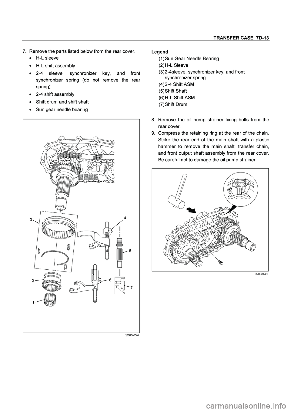
7.
Remove the parts listed below from the rear cover.
�
H-L sleeve
�
H-L shift assembly
�
2-4 sleeve, synchronizer key, and front
synchronizer spring (do not remove the rea
r
spring)
�
2-4 shift assembly
�
Shift drum and shift shaft
�
Sun gear needle bearing
260R300001
8.
Remove the oil pump strainer fixing bolts from the
rear cover.
9.
Compress the retaining ring at the rear of the chain.
Strike the rear end of the main shaft with a plastic
hammer to remove the main shaft, transfer chain,
and front output shaft assembly from the rear cover.
Be careful not to damage the oil pump strainer.
226R30001
Legend
(1) Sun Gear Needle Bearing
(2) H-L Sleeve
(3) 2-4sleeve, synchronizer key, and front
synchronizer spring
(4) 2-4 Shift ASM
(5) Shift Shaft
(6) H-L Shift ASM
(7) Shift Drum
Page 3609 of 4264

TRANSFER CASE 7D-21
Oil Pump
�
Remove foreign materials from the strainer. If the
strainer is damaged, replace it.
If the area into which the shaft is inserted is excessively
worn or damaged, replace the oil pump assembly.
Clutch Hub Spline Play
�
Set a dial indicator to the clutch hub to be measured.
�
Move the clutch hub as far as possible to both the
right and the left.
Note the dial indicator reading.
�
If the measured value exceeds the specified limit,
the clutch hub must be replaced.
Clutch hub spline play
Standard : 0 – 0.1 mm (0 – 0.004 in)
Limit : 0.2 mm (0.008 in)
226RS042
Bearings
1.
Inspect the condition of all the needles and ball
bearings. Wash bearings thoroughly in a cleaning
solvent. Apply compressed air to the bearings.
NOTE: Do not allow the bearings to spin. Turn them
slowly by hand. Spinning bearings may damage the
rollers.
2.
Lubricate the bearings with a light oil and check them
for roughness by slowly turning the race by hand.
Ball Bearing Play
1.
Use a dial indicator to measure the ball bearing play.
2.
If the measured value exceeds the specified limit, the
ball bearing must be replaced.
Limit : 0.2 mm (0.008 in)
226R3043
Synchronizers
The synchronizer hubs and sliding sleeves are a
selected assembly and should be kept together as
originally assembled.
Clean synchronizer components with clean solvent and
air dry.
Inspect the components for the following:
�
Teeth for wear, scuffs, nicks, burrs or breaks.
�
Keys and springs for wear, cracks or distortion,
replace if these conditions are present.
�
If scuffed, nicked or burred conditions cannot be
corrected with a soft stone or crocus cloth, replace
the component.
Page 3614 of 4264
7D-26 TRANSFER CASE
226R300003
11.
Use a press to install the 2-4 hub.
12.
Install the hub snap ring.
13.
Install the synchronizer key springs (2), the
synchronizer key, and the 2-4 sleeve to the 2-4 hub.
The key and the open end of the springs must be
facing in the opposite direction.
Legend
(1) Retaining Ring
(2) Carrier and Gear ASM
(3) Thrust Needle Bearing
(4) Sungear Input Shaft
(5) Planetary Dog Teeth
(6) Dog Teeth Snapring
Page 3615 of 4264
TRANSFER CASE 7D-27
14.
Insert the H-L sleeve into the main shaft.
226R300023
Legend
(1) H-L Sleeve
(3) Synchronizer Key and Key Spring
(2) 2-4 Sleeve
15.
Install the sleeve to the H-L shift assembly.
16.
Install the sleeve to the 2-4 shift assembly.
17.
Coat the area around each of the shift assembl
y
insertion holes (transfer case) with transfer oil.
18.
Install the main shaft together with the H-L shif
t
assembly and the 2-4 shift assembly to the shif
t
drum.
 Yes No
1
2
3Was the Antitheft System Check
performed?
Recheck the DTC.
1. Key position is “OFF” and keep the position")
, the")
 H-L Sleeve
(3) Synchronizer Key and Key Spring
(2) 2-4 Sleeve
15.
Install the sl")