Page 1785 of 4264

4JA1/4JH1 ENGINE DRIVEABILITY AND EMISSIONS 6E–413
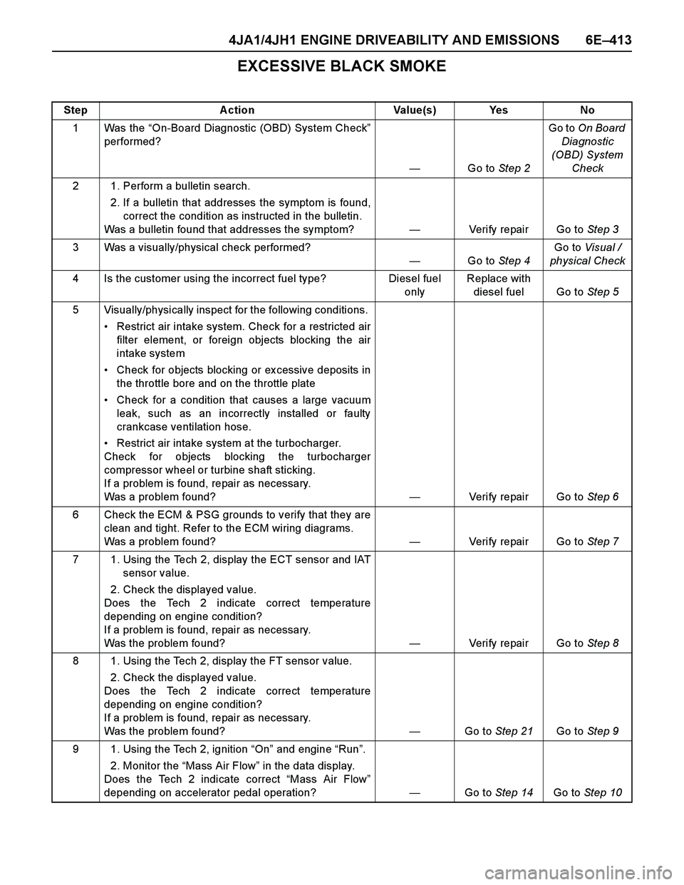
EXCESSIVE BLACK SMOKE
Step Action Value(s) Yes No
1Was the “On-Board Diagnostic (OBD) System Check”
performed?
—Go to Step 2Go to On Board
Diagnostic
(OBD) System
Check
2 1. Perform a bulletin search.
2. If a bulletin that addresses the symptom is found,
correct the condition as instructed in the bulletin.
Was a bulletin found that addresses the symptom?—Verify repair Go to Step 3
3 Was a visually/physical check performed?
—Go to Step 4Go to Visual /
physical Check
4 Is the customer using the incorrect fuel type? Diesel fuel
onlyReplace with
diesel fuel Go to Step 5
5 Visually/physically inspect for the following conditions.
Restrict air intake system. Check for a restricted air
filter element, or foreign objects blocking the air
intake system
Check for objects blocking or ex cessive deposits in
the throttle bore and on the throttle plate
Check for a condition that causes a large vacuum
leak, such as an incorrectly installed or faulty
crankcase ventilation hose.
Restrict air intake system at the turbocharger.
Check for objects blocking the turbocharger
compressor wheel or turbine shaft sticking.
If a problem is found, repair as necessary.
Was a problem found?—Verify repair Go to Step 6
6 Check the ECM & PSG grounds to verify that they are
clean and tight. Refer to the ECM wiring diagrams.
Was a problem found?—Verify repair Go to Step 7
7 1. Using the Tech 2, display the ECT sensor and IAT
sensor value.
2. Check the displayed value.
Does the Tech 2 indicate correct temperature
depending on engine condition?
If a problem is found, repair as necessary.
Was the problem found?—Verify repair Go to Step 8
8 1. Using the Tech 2, display the FT sensor value.
2. Check the displayed value.
Does the Tech 2 indicate correct temperature
depending on engine condition?
If a problem is found, repair as necessary.
Was the problem found?—Go to Step 21Go to Step 9
9 1. Using the Tech 2, ignition “On” and engine “Run”.
2. Monitor the “Mass Air Flow” in the data display.
Does the Tech 2 indicate correct “Mass Air Flow”
depending on accelerator pedal operation? —Go to Step 14Go to Step 10
Page 1795 of 4264

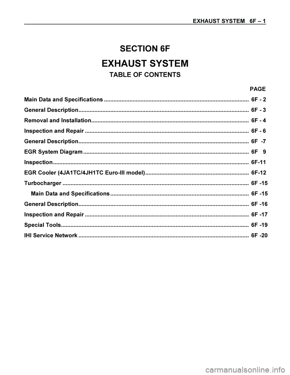
EXHAUST SYSTEM 6F – 1
SECTION 6F
EXHAUST SYSTEM
TABLE OF CONTENTS
PAGE
Main Data and Specifications ........................................................................................... 6F - 2
General Description........................................................................................................... 6F - 3
Removal and Installation................................................................................................... 6F - 4
Inspection and Repair ....................................................................................................... 6F - 6
General Description........................................................................................................... 6F -7
EGR System Diagram ........................................................................................................ 6F 9
Inspection ........................................................................................................................... 6F-11
EGR Cooler (4JA1TC/4JH1TC Euro-III model) ................................................................. 6F-12
Turbocharger ..................................................................................................................... 6F -15
Main Data and Specifications ....................................................................................... 6F -15
General Description........................................................................................................... 6F -16
Inspection and Repair ....................................................................................................... 6F -17
Special Tools...................................................................................................................... 6F -19
IHI Service Network ........................................................................................................... 6F -20
Page 1803 of 4264
EXHAUST SYSTEM 6F – 9
EGR SYSTEM DIAGRAM 4JA1T (L)
RTW46AMF000301
EGR System Operation
Inspect EGR valve motion visually while changing engine RPM under no load condition after warming-up.
Inspection point (Engine RPM)
RPM Idling
900 � 960 2000 3250
Engine Front Side VSV-1 ON ON ON OFF
Engine Rear Side VSV-2 ON OFF ON OFF
ON means VSV should receive signal to move EGR valve.
OFF means VSV shouldn’t receive signal to move EGR valve.
Page 1997 of 4264

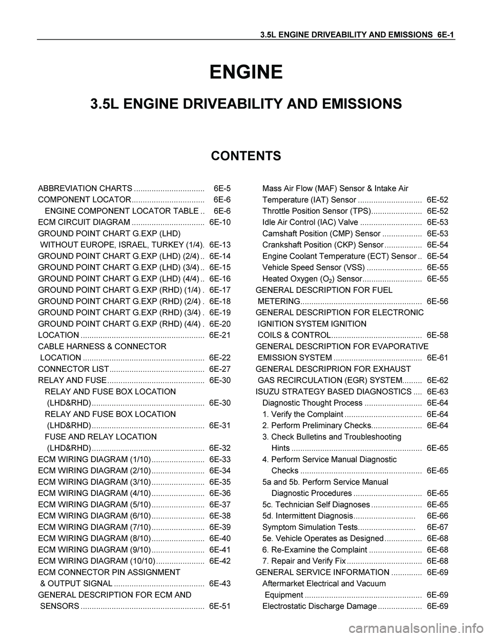
3.5L ENGINE DRIVEABILITY AND EMISSIONS 6E-1
ENGINE
3.5L ENGINE DRIVEABILITY AND EMISSIONS
CONTENTS
ABBREVIATION CHARTS ................................ 6E-5
COMPONENT LOCATOR ................................. 6E-6
ENGINE COMPONENT LOCATOR TABLE .. 6E-6
ECM CIRCUIT DIAGRAM ................................. 6E-10
GROUND POINT CHART G.EXP (LHD)
WITHOUT EUROPE, ISRAEL, TURKEY (1/4). 6E-13
GROUND POINT CHART G.EXP (LHD) (2/4) .. 6E-14
GROUND POINT CHART G.EXP (LHD) (3/4) .. 6E-15
GROUND POINT CHART G.EXP (LHD) (4/4) .. 6E-16
GROUND POINT CHART G.EXP (RHD) (1/4) . 6E-17
GROUND POINT CHART G.EXP (RHD) (2/4) . 6E-18
GROUND POINT CHART G.EXP (RHD) (3/4) . 6E-19
GROUND POINT CHART G.EXP (RHD) (4/4) . 6E-20
LOCATION ........................................................ 6E-21
CABLE HARNESS & CONNECTOR
LOCATION ....................................................... 6E-22
CONNECTOR LIST ........................................... 6E-27
RELAY AND FUSE ............................................ 6E-30
RELAY AND FUSE BOX LOCATION
(LHD&RHD) ................................................... 6E-30
RELAY AND FUSE BOX LOCATION
(LHD&RHD) ................................................... 6E-31
FUSE AND RELAY LOCATION
(LHD&RHD) ................................................... 6E-32
ECM WIRING DIAGRAM (1/10) ........................ 6E-33
ECM WIRING DIAGRAM (2/10) ........................ 6E-34
ECM WIRING DIAGRAM (3/10) ........................ 6E-35
ECM WIRING DIAGRAM (4/10) ........................ 6E-36
ECM WIRING DIAGRAM (5/10) ........................ 6E-37
ECM WIRING DIAGRAM (6/10) ........................ 6E-38
ECM WIRING DIAGRAM (7/10) ........................ 6E-39
ECM WIRING DIAGRAM (8/10) ........................ 6E-40
ECM WIRING DIAGRAM (9/10) ........................ 6E-41
ECM WIRING DIAGRAM (10/10) ...................... 6E-42
ECM CONNECTOR PIN ASSIGNMENT
& OUTPUT SIGNAL ......................................... 6E-43
GENERAL DESCRIPTION FOR ECM AND
SENSORS ........................................................ 6E-51
Mass Air Flow (MAF) Sensor & Intake Air
Temperature (IAT) Sensor ............................. 6E-52
Throttle Position Sensor (TPS)....................... 6E-52
Idle Air Control (IAC) Valve ............................ 6E-53
Camshaft Position (CMP) Sensor .................. 6E-53
Crankshaft Position (CKP) Sensor ................. 6E-54
Engine Coolant Temperature (ECT) Sensor .. 6E-54
Vehicle Speed Sensor (VSS) ......................... 6E-55
Heated Oxygen (O
2) Sensor........................... 6E-55
GENERAL DESCRIPTION FOR FUEL
METERING....................................................... 6E-56
GENERAL DESCRIPTION FOR ELECTRONIC
IGNITION SYSTEM IGNITION
COILS & CONTROL ......................................... 6E-58
GENERAL DESCRIPTION FOR EVAPORATIVE
EMISSION SYSTEM ........................................ 6E-61
GENERAL DESCRIPRION FOR EXHAUST
GAS RECIRCULATION (EGR) SYSTEM......... 6E-62
ISUZU STRATEGY BASED DIAGNOSTICS .... 6E-63
Diagnostic Thought Process .......................... 6E-64
1. Verify the Complaint ................................... 6E-64
2. Perform Preliminary Checks....................... 6E-64
3. Check Bulletins and Troubleshooting
Hints ........................................................... 6E-65
4. Perform Service Manual Diagnostic
Checks ....................................................... 6E-65
5a and 5b. Perform Service Manual
Diagnostic Procedures ............................... 6E-65
5c. Technician Self Diagnoses ....................... 6E-65
5d. Intermittent Diagnosis............................ 6E-66
Symptom Simulation Tests.......................... 6E-67
5e. Vehicle Operates as Designed ................. 6E-68
6. Re-Examine the Complaint ........................ 6E-68
7. Repair and Verify Fix .................................. 6E-68
GENERAL SERVICE INFORMATION .............. 6E-69
Aftermarket Electrical and Vacuum
Equipment ..................................................... 6E-69
Electrostatic Discharge Damage .................... 6E-69
Page 2006 of 4264
6E-10 3.5L ENGINE DRIVEABILITY AND EMISSIONS
ECM CIRCUIT DIAGRAM
RTW48AXF001401
Page 2029 of 4264
3.5L ENGINE DRIVEABILITY AND EMISSIONS 6E-33
ECM WIRING DIAGRAM (1/10)
RTW46EMF000401
Page 2030 of 4264
6E-34 3.5L ENGINE DRIVEABILITY AND EMISSIONS
ECM WIRING DIAGRAM (2/10)
RUW46EMF000101
Page 2031 of 4264
3.5L ENGINE DRIVEABILITY AND EMISSIONS 6E-35
ECM WIRING DIAGRAM (3/10)
RUW46EMF000201