Page 1067 of 4264
ELECTRICAL-BODY AND CHASSIS 8A-409
CIRCUIT DIAGRAM (LHD) Sheet 2/2
RTW48AXF025101
Page 1072 of 4264
8A-414 ELECTRICAL-BODY AND CHASSIS
CIRCUIT DIAGRAM
RTW48AXF028201
Page 1075 of 4264
ELECTRICAL-BODY AND CHASSIS 8A-417
CIRCUIT DIAGRAM
RTW48AXF012501
Page 1099 of 4264

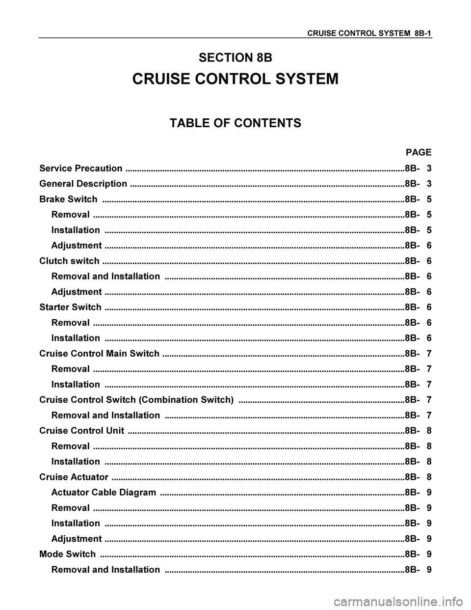
CRUISE CONTROL SYSTEM 8B-1
SECTION 8B
CRUISE CONTROL SYSTEM
TABLE OF CONTENTS
PAGE
Service Precaution .........................................................................................................................8B- 3
General Description .......................................................................................................................8B- 3
Brake Switch ...................................................................................................................................8B- 5
Removal .......................................................................................................................................8B- 5
Installation ..................................................................................................................................8B- 5
Adjustment ..................................................................................................................................8B- 6
Clutch switch ...................................................................................................................................8B- 6
Removal and Installation ........................................................................................................8B- 6
Adjustment ..................................................................................................................................8B- 6
Starter Switch ..................................................................................................................................8B- 6
Removal .......................................................................................................................................8B- 6
Installation ..................................................................................................................................8B- 6
Cruise Control Main Switch .........................................................................................................8B- 7
Removal .......................................................................................................................................8B- 7
Installation ..................................................................................................................................8B- 7
Cruise Control Switch (Combination Switch) ........................................................................8B- 7
Removal and Installation ........................................................................................................8B- 7
Cruise Control Unit ........................................................................................................................8B- 8
Removal .......................................................................................................................................8B- 8
Installation ..................................................................................................................................8B- 8
Cruise Actuator ...............................................................................................................................8B- 8
Actuator Cable Diagram ..........................................................................................................8B- 9
Removal .......................................................................................................................................8B- 9
Installation ..................................................................................................................................8B- 9
Adjustment ..................................................................................................................................8B- 9
Mode Switch ....................................................................................................................................8B- 9
Removal and Installation ........................................................................................................8B- 9
Page 1100 of 4264

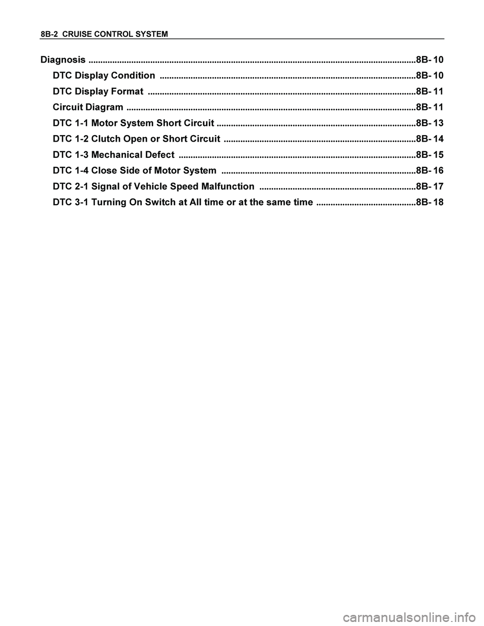
8B-2 CRUISE CONTROL SYSTEM
Diagnosis ..........................................................................................................................................8B- 10
DTC Display Condition ............................................................................................................8B- 10
DTC Display Format .................................................................................................................8B- 11
Circuit Diagram ..........................................................................................................................8B- 11
DTC 1-1 Motor System Short Circuit ....................................................................................8B- 13
DTC 1-2 Clutch Open or Short Circuit .................................................................................8B- 14
DTC 1-3 Mechanical Defect ....................................................................................................8B- 15
DTC 1-4 Close Side of Motor System ..................................................................................8B- 16
DTC 2-1 Signal of Vehicle Speed Malfunction ..................................................................8B- 17
DTC 3-1 Turning On Switch at All time or at the same time ..........................................8B- 18
Page 1106 of 4264
8B-8 CRUISE CONTROL SYSTEM
Cruise Control Unit
RTW3A0SH001101
Removal
1. Disconnect the battery ground cable.
2. Remove the dash side trim panel (LH) (1).
3. Disconnect the connector.
4. Remove a fixing nut to remove the cruise control unit (2).
Installation
To install, follow the removal steps in the reverse order.
Cruise Actuator
Actuator Cable Diagram
RTW3A0SF000301
Legend
(1) Cruise Actuator Assembly
(2) Cruise Control Cable
(3) Accelerator Cable
(4) Throttle Link (Cruise Control Side)
Page 1110 of 4264
8B-12 CRUISE CONTROL SYSTEM
CIRCUIT DIAGRAM
RTW48AXF003801
Page 1341 of 4264
ENGINE ELECTRICAL 6D – 3
GENERAL DESCRIPTION
GENERATOR STARTER MOTOR
066L300004065L300002
The basic charging system is the IC integral regulator charging system. The internal components are connected
electrically as shown in charging circuit diagram.
The generator features a solid state regulator that is mounted inside the generator. All regulator components are
enclosed into a solid mold, and this unit along with the brush holder assembly is attached to the slip ring end frame.
The generator voltage setting cannot be adjusted.
The starter motor circuit is composed of a 4-pole 4-brush type direct current series motor. The starter motor circuit
utilizes negative ground polarity.