Page 1860 of 4264
6A-36 ENGINE MECHANICAL (6VE1 3.5L)
014RW024
Legend
(1) Right Bank
(2) Left Bank
(3) Alignment Mark on Camshaft Drive Gear
(4) Alignment Mark on Camshaft
(5) Alignment Mark on Retainer
3. Tighten twenty bolts on numerical order an one
side bank as shown in the illustration.
Torque : 10 N�
�� �m (1.0 kg�
�� �m/7 lb ft)
014RW031
5. Install cylinder head cover RH.
� Refer to installation procedure for CYLINDER
HEAD COVER RH in this manual.
6. Install cylinder head cover LH.
� Refer to installation procedure for CYLINDER
HEAD COVER LH in this manual.
7. Install timing belt.
� Refer to installation procedure for TIMING
BELT in this manual. 8. Install crankshaft pulley.
� Refer to installation procedure fo
r
CRANKSHAFT PULLEY in this manual.
Page 1861 of 4264
 6A-37
Cylinder Head
Removal
1. Remove engine hood.
2. Disconnect battery ground cable.
3. Drain radiator coolant.
4. Drain engine oil.
5. Remove crankshaft pulley")
ENGINE MECHANICAL (6VE1 3.5L) 6A-37
Cylinder Head
Removal
1. Remove engine hood.
2. Disconnect battery ground cable.
3. Drain radiator coolant.
4. Drain engine oil.
5. Remove crankshaft pulley.
� Refer to removal procedure for Crankshaf
t
Pulley in this manual.
6. Remove timing belt.
� Refer to removal procedure for Timing Belt in
this manual.
7. Remove cylinder head cover LH.
� Refer to removal procedure for Cylinder Head
Cover LH in this manual.
8. Remove cylinder head cover RH.
� Refer to removal procedure for Cylinder Head
Cover RH in this manual.
9. Remove common chamber.
� Refer to removal procedure for Common
Chamber in this manual.
10. Remove cylinder head assembly.
1. Loosen eights bolts for tight cylinder head.
2. Remove cylinder head assembly.
014RW028
Legend
(1) Cylinder Head
(2) Cylinder Head Bolt
(3) Camshaft
Installation
1. Install cylinder head assembly to cylinder block.
1. Put cylinder head gasket on the cylinder block.
NOTE: There is discrimination mark “R" for righ
t
bank and “L" for left bank on the cylinder head
gasket as shown in the illustration.
Do not reuse cylinder head gasket.
011RW005
2. Align dowel pin hole to dowel pin on the
cylinder block.
3. Tighten two bolts temporarily by hand to
prevent the cylinder head assembly from
moving.
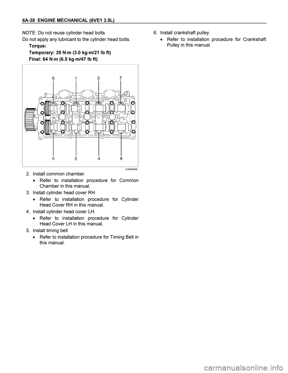
4. Using 9�8511�4209�0 cylinder head bol
t
wrench, tighten bolts in numerical order as
shown in the illustration to the specified torque.
Page 1862 of 4264
6A-38 ENGINE MECHANICAL (6VE1 3.5L)
NOTE: Do not reuse cylinder head bolts.
Do not apply any lubricant to the cylinder head bolts.
Torque:
Temporary: 29 N�
�� �m (3.0 kg�
�� �m/21 lb ft)
Final: 64 N�
�� �m (6.5 kg�
�� �m/47 lb ft)
014RW029
2. Install common chamber.
� Refer to installation procedure for Common
Chamber in this manual.
3. Install cylinder head cover RH.
� Refer to installation procedure for Cylinde
r
Head Cover RH in this manual.
4. Install cylinder head cover LH.
� Refer to installation procedure for Cylinde
r
Head Cover LH in this manual.
5. Install timing belt.
� Refer to installation procedure for Timing Belt in
this manual. 6. Install crankshaft pulley.
� Refer to installation procedure for Crankshaf
t
Pulley in this manual.
Page 1867 of 4264
ENGINE MECHANICAL (6VE1 3.5L) 6A-43
Crankshaft and Main Bearings
Removal
F06RW010
Legend
(1) Engine Assembly
(2) Crankshaft Pulley
(3) Timing Belt Cover
(4) Timing Belt
(5) Crankcase with Oil Pan
(6) Oil Pipe
(7) Oil Strainer
(8) Oil Pump Assembly
(9) Cylinder Body Side Bolt
(10) Oil Gallery
(11) Flywheel
(12) Rear Oil Seal Retainer
(13) Connecting Rod Cap
(14) Crankshaft Main Bearing Cap
(15) Crankshaft and Main Bearing
Page 1868 of 4264

1. Remove engine assembly.
� Refer to removal procedure for Engine
Assembly in this manual.
2. Remove timing belt.
� Refer to removal procedure for Timing Belt")
6A-44 ENGINE MECHANICAL (6VE1 3.5L)
1. Remove engine assembly.
� Refer to removal procedure for Engine
Assembly in this manual.
2. Remove timing belt.
� Refer to removal procedure for Timing Belt in
this manual.
3. Remove oil pan and crankcase.
� Refer to removal procedure for Oil Pan and
Crankcase in this manual.
4. Remove oil pipe with O-ring.
5. Remove oil strainer assembly with O-ring.
6. Remove oil pump assembly.
� Refer to removal procedure for Oil Pump in this
manual.
7. Remove cylinder body side bolts.
8. Remove oil gallery.
9. Remove flywheel.
10. Remove rear oil seal retainer.
� Refer to removal procedure for Rear Oil Seal in
this manual.
11. Remove connecting rod caps.
12. Remove crankshaft main bearing caps.
13. Remove crankshaft and main bearings.
Installation
1. Install crankshaft and main bearings.
� Install main bearing in the cylinder block and
main bearing cap respectively.
Apply new engine oil to upper and lower main
bearings.
NOTE:
� Do not apply engine oil to the bearing back faces.
� Make sure that main bearings are in correc
t
position.
� Install crankshaft with care.
� Apply engine oil to the thrust washer.
� Install thrust washer on No.3 journal.
� Oil grooves in thrust washer must face the
crankshaft.
015RS012
015RS013
2. Install crankshaft main bearing caps.
�
Apply engine oil to the thread and seating
surface of each bearing cap fixing bolt.
NOTE:
� Do not apply engine oil to the bearing back faces.
� Install bearing caps in the order of numbers,
starting with cylinder block front side.
� Tighten main bearing fixing bolts to the specified
torque.
Torque: 39 N�
�� �m (4.0 kg�
�� �m/29 lb ft)
�
After tightening the bolts, make sure that the
crankshaft rotates smoothly.
3. Install connecting rod caps.
� The cap number must be same as connecting
rod number.
�
Apply engine oil to the thread and seating
surface of each nut.
Page 1871 of 4264
 6A-47
11. Install crankcase.
� Remove oil on crankcase mounting surface
and dry the surface.
� Properly apply a 4.5 mm (0.7 in) wide bead o
f
sealant (TB1207C or equi")
ENGINE MECHANICAL (6VE1 3.5L) 6A-47
11. Install crankcase.
� Remove oil on crankcase mounting surface
and dry the surface.
� Properly apply a 4.5 mm (0.7 in) wide bead o
f
sealant (TB1207C or equivalent) to the
crankcase mounting surface. The bead mus
t
be continuous.
� The crankcase must be installed within 5
minutes after sealant application to preven
t
premature hardening of sealant.
� Tighten fixing bolts to the specified torque.
Torque: 10 N�
�� �m (1.0 kg�
�� �m/1 lb ft)
013RW010
013RW004
12. Install oil pan
� Remove oil on oil pan mounting surface and
dry the surface.
� Properly apply a 4.5 mm (0.7 in) wide bead o
f
sealant (TB1207C or equivalent) to the oil pan
mounting surface. The bead must be
continuous.
� The oil pan must be installed within 5 minutes
after sealant application to prevent premature
hardening of sealant.
� Tighten fixing bolts to the specified torque.
Torque: 25 N�
�� �m (2.5 kg�
�� �m/18 lb ft)
013RW003
013RW002
13. Install timing belt.
� Refer to installation procedure for Timing Belt in
this manual.
14. Install engine assembly.
� Refer to installation procedure for Engine
Assembly in this manual.
Page 1917 of 4264
ENGINE MECHANICAL (6VE1 3.5L) 6A-93
Main Data and Specification
General Specification
Item Specifications
Engine type, number of cylinders and arrangement Water cooled, four cycle V6
Form of combustion chamber Pent-roof type
Valve mechanism 4-Cams, 4-Valves, DOHC Gear & Belt Drive
Cylinder liner type Casted in cylinder block
Total piston displacement 3494 cc
Cylinder bore x stroke 93.4mm x 85.0mm
(3.6772 in � 3.3465 in)
Compression ratio 8.6
Compression pressure at 300rpm 1.37 MPa (14.0 Kg/cm2)
Engine idling speed rpm Non adjustable (750)
Valve clearance Intake: 0.28 mm (0.11 in)
Exhaust: 0.30mm (0.12 in)
Oil capacity 5.3 liters
Ignition timing
Non adjustable (12� BTDC at idle rpm)
Spark plug PK16PR11, RC10PYP4, K16PR-P11
Plug gap 1.0 mm – 1.1 mm (0.0394 in – 0.0433 in)
Page 1920 of 4264
6A-96 ENGINE MECHANICAL (6VE1 3.5L)
Crankshaft main bearing, Flywheel, Crankcase, Oil pan, Timing belt tensioner, Timing pulley, timing belt
cover, Oil pump, Oil gallery, Oil strainer and water pump
N�
�� �m (kg�
�� �m/ lb ft)
RTW46ALF000701

014RW024
Legend
(1) Right Bank
(2) Left Bank
(3) Alignment Mark on Camshaft Drive Gear
(4) Alignment Mark on Camshaft
(5) Alignment Mark on Re")
 6A-43
Crankshaft and Main Bearings
Removal
F06RW010
Legend
(1) Engine Assembly
(2) Crankshaft Pulley
(3) Timing Belt Cover
(4) Timing Belt
(5) C")
 6A-93
Main Data and Specification
General Specification
Item Specifications
Engine type, number of cylinders and arrangement Water cooled, four cycle V6
Form of")

Crankshaft main bearing, Flywheel, Crankcase, Oil pan, Timing belt tensioner, Timing pulley, timing belt
cover, Oil pump, Oil gallery, Oil strainer and water pum")