Page 1927 of 4264
ENGINE COOLING (6VE1 3.5L) 6B-3
Water Pump
The EC pump is a centrifugal impeller type and is driven
by a timing belt.
030RS001
Thermostat
The thermostat is a wax pellet type with a air hole(1)
and is installed in the thermostat housing.
031RW002
Radiator
The radiator is a tube type with corrugated fins. In order
to raise the boiling point of the coolant, the radiator is
fitted with a cap in which the valve is operated at 93.3
�
122.7 kPa (13.5 � 17.8 psi) pressure. (No oil cooler
provided for M/T)
110RS001
Antifreeze Solution
Calculating mixing ratio
F06RW005
Page 1931 of 4264
ENGINE COOLING (6VE1 3.5L) 6B-7
Water Pump
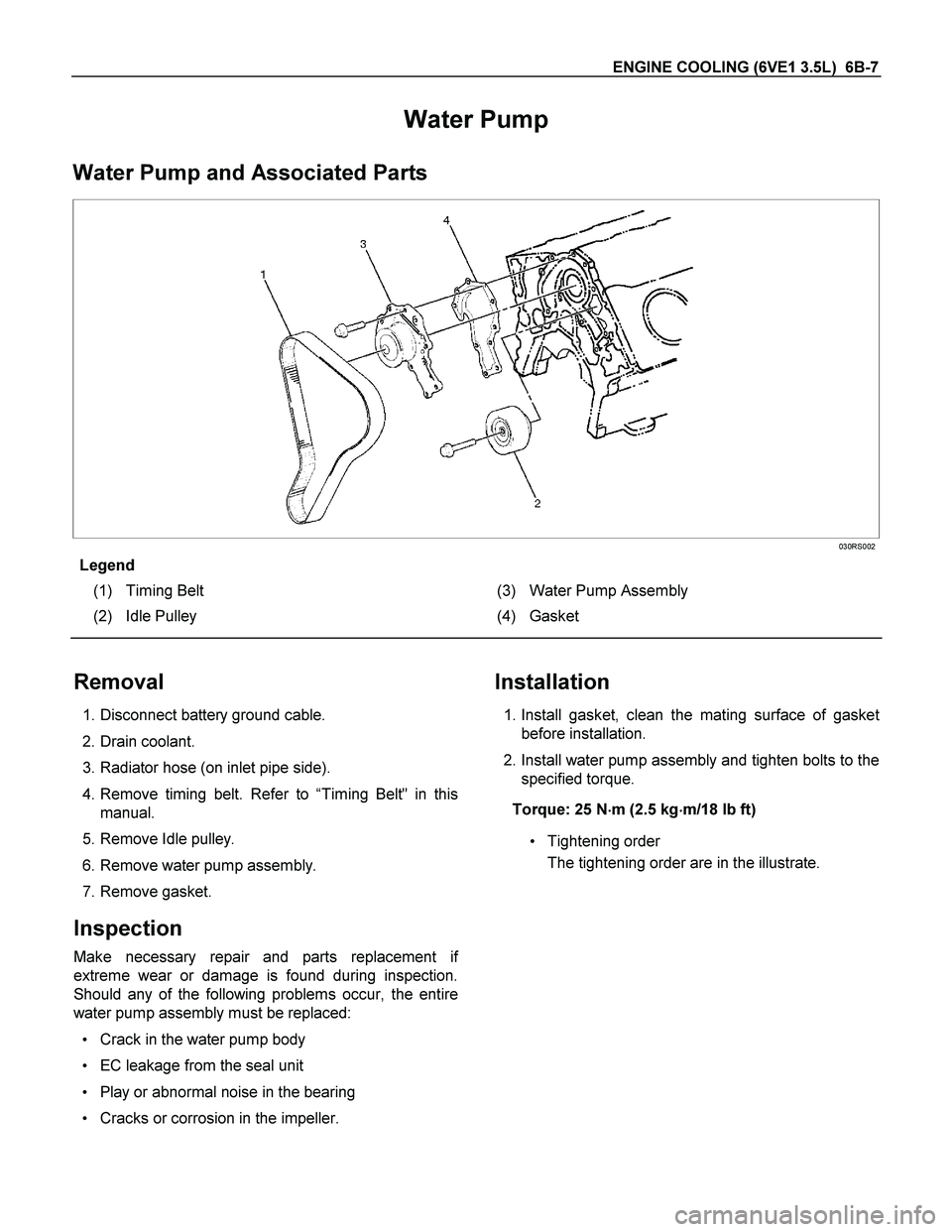
Water Pump and Associated Parts
030RS002
Legend
(1) Timing Belt (3) Water Pump Assembly
(2) Idle Pulley (4) Gasket
Removal
1. Disconnect battery ground cable.
2. Drain coolant.
3. Radiator hose (on inlet pipe side).
4. Remove timing belt. Refer to “Timing Belt" in this
manual.
5. Remove Idle pulley.
6. Remove water pump assembly.
7. Remove gasket.
Inspection
Make necessary repair and parts replacement if
extreme wear or damage is found during inspection.
Should any of the following problems occur, the entire
water pump assembly must be replaced:
Crack in the water pump body
EC leakage from the seal unit
Play or abnormal noise in the bearing
Cracks or corrosion in the impeller.
Installation
1. Install gasket, clean the mating surface of gasket
before installation.
2. Install water pump assembly and tighten bolts to the
specified torque.
Torque: 25 N�
�� �m (2.5 kg�
�� �m/18 lb ft)
Tightening order
The tightening order are in the illustrate.
Page 1932 of 4264
6B-8 ENGINE COOLING (6VE1 3.5L)
NOTE: To prevent the oil leakage, apply the LOCTITE
262 or an equivalent, to the arrow marked fixing bol
t
thread.
030RW008
3. Idle pulley
Install idle pulley and tighten bolt to the specified
torque.
Torque: 52 N�
�� �m (5.3 kg�
�� �m/38 lb ft)
4. Timing belt
Install timing belt. Refer to timing belt installation
step in “Timing Belt" in this manual.
5. Connect radiator inlet hose and replenish EC.
6. Connect battery ground cable.
Page 2336 of 4264
6E-340 3.5L ENGINE DRIVEABILITY AND EMISSIONS
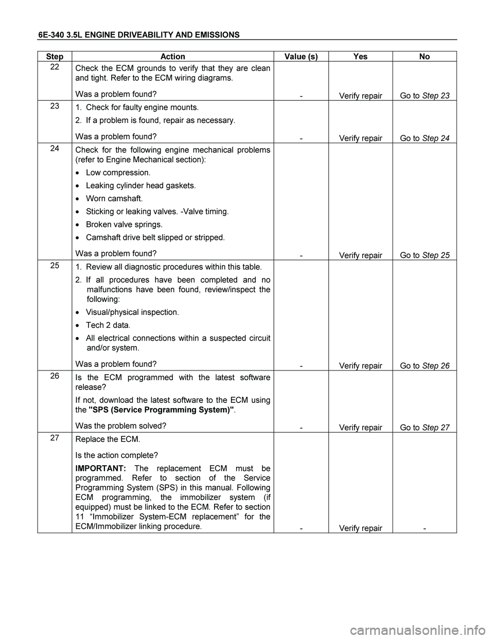
Step Action Value (s) Yes No
22
Check the ECM grounds to verify that they are clean
and tight. Refer to the ECM wiring diagrams.
Was a problem found?
- Verify repair Go to Step 23
23
1. Check for faulty engine mounts.
2. If a problem is found, repair as necessary.
Was a problem found?
- Verify repair Go to Step 24
24
Check for the following engine mechanical problems
(refer to Engine Mechanical section):
� Low compression.
� Leaking cylinder head gaskets.
� Worn camshaft.
� Sticking or leaking valves. -Valve timing.
� Broken valve springs.
� Camshaft drive belt slipped or stripped.
Was a problem found?
- Verify repair Go to Step 25
25
1. Review all diagnostic procedures within this table.
2. If all procedures have been completed and no
malfunctions have been found, review/inspect the
following:
� Visual/physical inspection.
� Tech 2 data.
� All electrical connections within a suspected circuit
and/or system.
Was a problem found?
- Verify repair Go to Step 26
26
Is the ECM programmed with the latest software
release?
If not, download the latest software to the ECM using
the "SPS (Service Programming System)".
Was the problem solved?
- Verify repair Go to Step 27
27
Replace the ECM.
Is the action complete?
IMPORTANT: The replacement ECM must be
programmed. Refer to section of the Service
Programming System (SPS) in this manual. Following
ECM programming, the immobilizer system (if
equipped) must be linked to the ECM. Refer to section
11 “Immobilizer System-ECM replacement” for the
ECM/Immobilizer linking procedure.
- Verify repair -
Page 2347 of 4264
3.5L ENGINE DRIVEABILITY AND EMISSIONS 6E-351
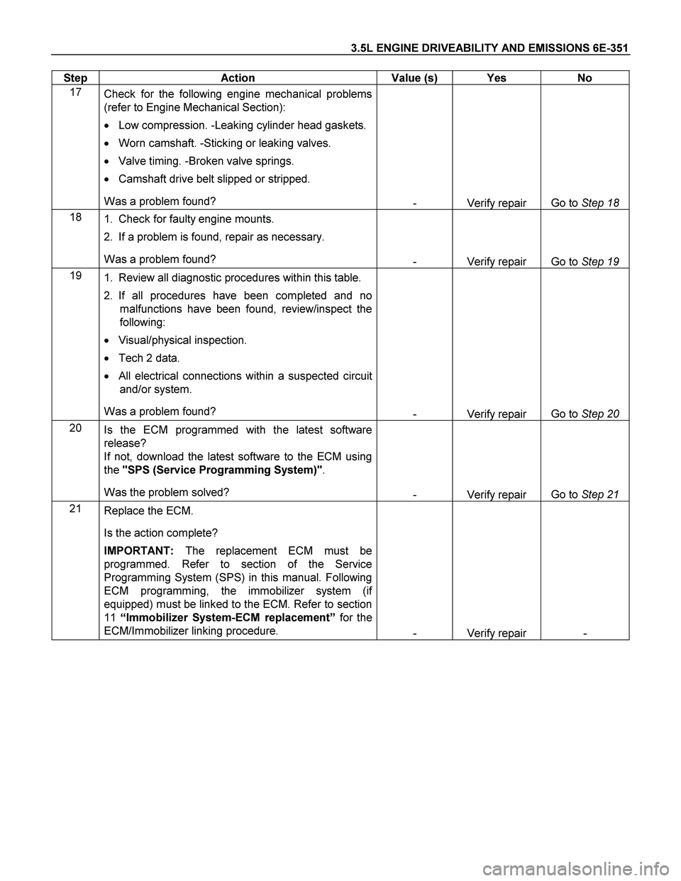
Step Action Value (s) Yes No
17
Check for the following engine mechanical problems
(refer to Engine Mechanical Section):
� Low compression. -Leaking cylinder head gaskets.
� Worn camshaft. -Sticking or leaking valves.
� Valve timing. -Broken valve springs.
� Camshaft drive belt slipped or stripped.
Was a problem found?
- Verify repair Go to Step 18
18
1. Check for faulty engine mounts.
2. If a problem is found, repair as necessary.
Was a problem found?
- Verify repair Go to Step 19
19
1. Review all diagnostic procedures within this table.
2. If all procedures have been completed and no
malfunctions have been found, review/inspect the
following:
� Visual/physical inspection.
� Tech 2 data.
� All electrical connections within a suspected circuit
and/or system.
Was a problem found?
- Verify repair Go to Step 20
20
Is the ECM programmed with the latest software
release?
If not, download the latest software to the ECM using
the "SPS (Service Programming System)".
Was the problem solved?
- Verify repair Go to Step 21
21
Replace the ECM.
Is the action complete?
IMPORTANT: The replacement ECM must be
programmed. Refer to section of the Service
Programming System (SPS) in this manual. Following
ECM programming, the immobilizer system (if
equipped) must be linked to the ECM. Refer to section
11 “Immobilizer System-ECM replacement” for the
ECM/Immobilizer linking procedure.
- Verify repair -
Page 2350 of 4264
6E-354 3.5L ENGINE DRIVEABILITY AND EMISSIONS
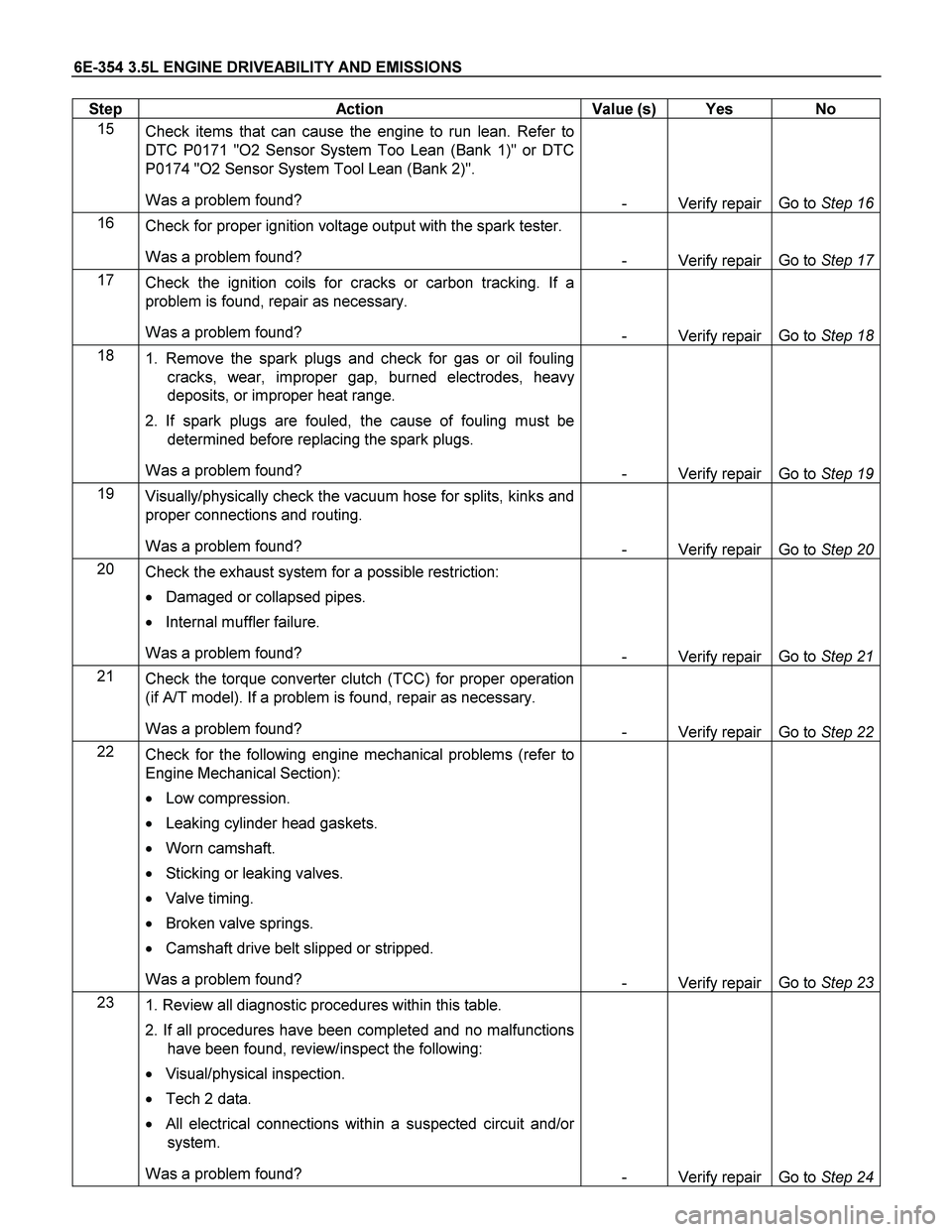
Step Action Value (s) Yes No
15
Check items that can cause the engine to run lean. Refer to
DTC P0171 "O2 Sensor System Too Lean (Bank 1)" or DTC
P0174 "O2 Sensor System Tool Lean (Bank 2)".
Was a problem found?
- Verify repair Go to Step 16
16
Check for proper ignition voltage output with the spark tester.
Was a problem found?
- Verify repair Go to Step 17
17
Check the ignition coils for cracks or carbon tracking. If a
problem is found, repair as necessary.
Was a problem found?
- Verify repair Go to Step 18
18
1. Remove the spark plugs and check for gas or oil fouling
cracks, wear, improper gap, burned electrodes, heavy
deposits, or improper heat range.
2. If spark plugs are fouled, the cause of fouling must be
determined before replacing the spark plugs.
Was a problem found?
- Verify repair Go to Step 19
19
Visually/physically check the vacuum hose for splits, kinks and
proper connections and routing.
Was a problem found?
- Verify repair Go to Step 20
20
Check the exhaust system for a possible restriction:
� Damaged or collapsed pipes.
� Internal muffler failure.
Was a problem found?
- Verify repair Go to Step 21
21
Check the torque converter clutch (TCC) for proper operation
(if A/T model). If a problem is found, repair as necessary.
Was a problem found?
- Verify repair Go to Step 22
22
Check for the following engine mechanical problems (refer to
Engine Mechanical Section):
� Low compression.
� Leaking cylinder head gaskets.
� Worn camshaft.
� Sticking or leaking valves.
� Valve timing.
� Broken valve springs.
� Camshaft drive belt slipped or stripped.
Was a problem found?
- Verify repair Go to Step 23
23
1. Review all diagnostic procedures within this table.
2. If all procedures have been completed and no malfunctions
have been found, review/inspect the following:
� Visual/physical inspection.
� Tech 2 data.
� All electrical connections within a suspected circuit and/or
system.
Was a problem found?
- Verify repair Go to Step 24
Page 2363 of 4264
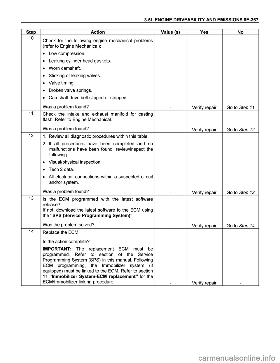
3.5L ENGINE DRIVEABILITY AND EMISSIONS 6E-367
Step Action Value (s) Yes No
10
Check for the following engine mechanical problems
(refer to Engine Mechanical):
� Low compression.
� Leaking cylinder head gaskets.
� Worn camshaft.
� Sticking or leaking valves.
� Valve timing.
� Broken valve springs.
� Camshaft drive belt slipped or stripped.
Was a problem found?
- Verify repair Go to Step 11
11
Check the intake and exhaust manifold for casting
flash. Refer to Engine Mechanical.
Was a problem found?
- Verify repair Go to Step 12
12
1. Review all diagnostic procedures within this table.
2. If all procedures have been completed and no
malfunctions have been found, review/inspect the
following:
� Visual/physical inspection.
� Tech 2 data.
� All electrical connections within a suspected circuit
and/or system.
Was a problem found?
- Verify repair Go to Step 13
13
Is the ECM programmed with the latest software
release?
If not, download the latest software to the ECM using
the "SPS (Service Programming System)".
Was the problem solved?
- Verify repair Go to Step 14
14
Replace the ECM.
Is the action complete?
IMPORTANT: The replacement ECM must be
programmed. Refer to section of the Service
Programming System (SPS) in this manual. Following
ECM programming, the Immobilizer system (if
equipped) must be linked to the ECM. Refer to section
11 “Immobilizer System-ECM replacement” for the
ECM/Immobilizer linking procedure.
- Verify repair -
Page 2393 of 4264
ENGINE LUBRICATION (6VE1 3.5L) 6G-9
Oil Pump
Removal
1. Disconnect battery ground cable.
2. Drain engine oil.
3. Remove crankcase assembly.
Refer to removal procedure for Oil Pan and
Crankcase in this manual.
4. Remove crankshaft pulley.
Refer to removal procedure for Crankshaf
t
Pulley in this manual.
5. Remove timing belt.
Refer to removal procedure for Timing Belt in
this manual.
6. Remove timing pulley from crankshaft.
7. Remove four fixing bolts from oil filter assembly.
8. Remove oil strainer fixing bolts, remove oil straine
r
assembly with O-ring.
9. Remove three bolts from oil pipe and O-ring.
10. Remove eight oil pump fixing bolts, then oil pump
assembly.
11. Remove sealant from mounting surface of oil pump
assembly, cylinder block and take care not to
damage mounting surfaces of oil pump and cylinde
r
block.
Installation
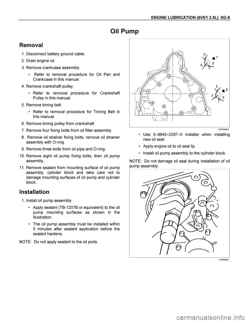
1. Install oil pump assembly
Apply sealant (TB-1207B or equivalent) to the oil
pump mounting surfaces as shown in the
illustration.
The oil pump assembly must be installed within
5 minutes after sealant application before the
sealant hardens.
NOTE: Do not apply sealant to the oil ports.
051RW002
Use 5–8840–2287–0 installer when installing
new oil seal.
Apply engine oil to oil seal lip.
Install oil pump assembly to the cylinder block.
NOTE: Do not damage oil seal during installation of oil
pump assembly.
015RS001