Page 391 of 4264
BRAKE CONTROL SYSTEM 5A-75
DTC C0265 (Flash Code 65) Fail Safe Relay (FSR) Shorted to Ground
DTC C0266 (Flash Code 66) Fail Safe Relay (FSR) Shorted to Battery
RTW45AMF000201
Step Action
Value(s) Yes No
1 Was the “Basic Diagnostic Flow Chart” performed?
- Go to Step 2 Go to Basic
Diagnostic
Flow Chart
2 1. Ignition “OFF”.
2. Check the EHCU circuit for an open, short to
ground, or short to voltage. Also, check the EHCU
ignition feed circuit for an open or short to ground
and the EHCU ground circuit for an open or short to
voltage.
3. If a problem is found, repair as necessary.
Was a problem found?
- Verify repair Go to Step 3
3 1. Ignition “ON,” engine “OFF.”
2. Select “Display DTCs” with the Tech 2.
Note: Perform the various tests (actuator test, test
run, brake test, etc.) then observe the DTC with a
Tech2.
Are any DTCs stored? - Go to Step 4 Verify repair
Page 659 of 4264

ELECTRICAL-BODY AND CHASSIS 8A-1
SECTION 8A
ELECTRICAL-BODY AND CHASSIS
TABLE OF CONTENTS
PAGE
General Information ........................................................................................................ 8A- 4
Notes for Working on Electrical Items .......................................................................... 8A- 5
Symbols and Abbreviations ........................................................................................... 8A- 11
Symbols ...................................................................................................................... 8A- 11
Abbreviations ............................................................................................................. 8A- 12
Parts for Electrical Circuit .............................................................................................. 8A- 13
Wiring .......................................................................................................................... 8A- 13
Fuse ............................................................................................................................. 8A- 15
Fusible Link ................................................................................................................ 8A- 15
Relay ............................................................................................................................ 8A- 16
Diode ........................................................................................................................... 8A- 17
Connector ................................................................................................................... 8A- 18
Battery ......................................................................................................................... 8A- 19
Reading the Circuit Diagram .......................................................................................... 8A- 22
Parts Location ............................................................................................................ 8A- 22
Circuit Diagram ........................................................................................................... 8A- 23
Connector List ............................................................................................................. 8A- 23
Main Data and Specifications ........................................................................................ 8A- 24
Bulb Specifications .................................................................................................... 8A- 24
Relay and Fuse ................................................................................................................ 8A- 26
Relay and Fuse Box Location ................................................................................... 8A- 26
Relay Location ............................................................................................................ 8A- 28
Page 660 of 4264

8A-2 ELECTRICAL-BODY AND CHASSIS
PAGE
Fuse and Slow Blow Fuse Location (Relay and Fuse Box) .................................... 8A- 31
Fuse Location ............................................................................................................. 8A- 33
Diode Location ........................................................................................................... 8A- 34
Fuse Block Circuit ...................................................................................................... 8A- 35
Fuse Block Circuit (C24SE) ....................................................................................... 8A- 35
Fuse Block Circuit (6VE1) ......................................................................................... 8A- 37
Fuse Block Circuit (4JA1-TC/4JH1-TC) - RHD ......................................................... 8A- 39
Fuse Block Circuit (4JA1-TC/4JH1-TC) – LHD ......................................................... 8A- 41
Fuse Block Circuit (4JH1-L) ...................................................................................... 8A- 43
Grounding Point ............................................................................................................. 8A- 45
Ground Point .............................................................................................................. 8A- 45
Ground Point Location .............................................................................................. 8A- 61
Main Cable harness Routing .......................................................................................... 8A- 63
C24SE / 6VE1 / 4JA1-L / 4JH1-TC .............................................................................. 8A- 63
Instrument Harness .................................................................................................... 8A- 71
System Repair .................................................................................................................8A- 73
Start and Charging ..................................................................................................... 8A- 73
Engine Control Module (ECM) ................................................................................... 8A- 89
Exhaust Gas Recalculation (EGR): 4JA1-L Only ...................................................... 8A- 109
Lighting ....................................................................................................................... 8A- 114
Front Fog Light ........................................................................................................... 8A- 136
Rear Fog Light ............................................................................................................ 8A- 144
Head Light Leveling ................................................................................................... 8A- 149
Illumination ................................................................................................................. 8A- 154
Hazard Warning Flasher, Turn Signal Light, Back Up Light,
Horn and Stop Light ................................................................................................. 8A- 161
Dome Light, Spot Light and Warning Buzzer .......................................................... 8A- 181
Windshield Wiper and Washer .................................................................................. 8A- 196
Transmission Control Module (TCM) ....................................................................... 8A- 214
Meter, Warning Light and Indicator Light ................................................................ 8A- 223
Heater and Air Conditioning ...................................................................................... 8A- 281
Power Door Lock ....................................................................................................... 8A- 293
Page 662 of 4264

8A-4 ELECTRICAL-BODY AND CHASSIS
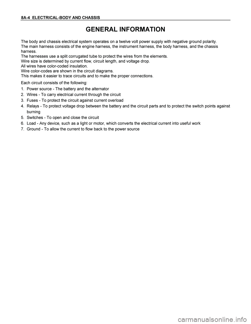
GENERAL INFORMATION
The body and chassis electrical system operates on a twelve volt power supply with negative ground polarity.
The main harness consists of the engine harness, the instrument harness, the body harness, and the chassis
harness.
The harnesses use a split corrugated tube to protect the wires from the elements.
Wire size is determined by current flow, circuit length, and voltage drop.
All wires have color-coded insulation.
Wire color-codes are shown in the circuit diagrams.
This makes it easier to trace circuits and to make the proper connections.
Each circuit consists of the following:
1. Power source - The battery and the alternator
2. Wires - To carry electrical current through the circuit
3. Fuses - To protect the circuit against current overload
4. Relays - To protect voltage drop between the battery and the circuit parts and to protect the switch points against
burning
5. Switches - To open and close the circuit
6. Load - Any device, such as a light or motor, which converts the electrical current into useful work
7. Ground - To allow the current to flow back to the power source
Page 669 of 4264
ELECTRICAL-BODY AND CHASSIS 8A-11
SYMBOLS AND ABBREVIATIONS
SYMBOLS
Symbol Meaning of Symbol Symbol Meaning of Symbol
Fuse
Bulb
Fusible link
Double filament bulb
Fusible link wire
Motor
Switch
Variable resistor Rheostat
Switch
Coil (inductor), solenoid,
magnetic valve
Switch (Normal close type)
Contact wiring
Relay
Battery
Diode
Connector
Electronic Parts
Light emitting diode
Resistor
Reed switch
Speaker
Condenser
Buzzer
Horn
Circuit breaker
Vacuum switching valve
Page 674 of 4264
8A-16 ELECTRICAL-BODY AND CHASSIS
RELAY
Battery and load location may require that a switch be placed
some distance from either component.
This means a longer wire and a higher voltage drop
1. The
installation of a relay between the battery and the load reduces
the voltage drop
2.
Because the switch controls the relay, amperage through the
switch can be reduced.
Relay Specifications and Configurations
Name/
Color Rated
voltage/ Coil
resistance Internal circuit Name/
color Rated
Voltage/Coil
resistance Internal circuit
1T
(MICRO
ISO)
/Black 12V
Approx. 92�
Minimum
operating
voltage: 7V at
20�C (77�F)
1M (MINI
ISO)
/Black 12V Approx.
94� Minimum
operating
voltage: 7V at
20�C (77�F)
1M
(MICRO
ISO)
/Black 12V
Approx. 132-3
� Minimum
operating
voltage: 7V at
20�C (77�F)
1M
(power)/
Black 12V Approx.
94� Minimum
operating
voltage: 7V at
20�C (77�F)
* Relay contact shown in the wiring diagram indicates condition before actuation.
Page 684 of 4264
8A-26 ELECTRICAL-BODY AND CHASSIS
RELAY AND FUSE
RELAY AND FUSE BOX LOCATION (RHD)
Page 685 of 4264
ELECTRICAL-BODY AND CHASSIS 8A-27
RELAY AND FUSE BOX LOCATION (LHD)
RTW48ALF000201