Page 3419 of 4264

FRONT ALIGNMENT 3A-3
Inspection
Before making any adjustments affecting caster, camber or
toe-in, the following front end inspection should be made.
1. Inspect the tires for proper inflation pressure. Refer to
Main Data and Specifications in Wheel and Tire System
section.
2. Make sure that the vehicle is unlade condition (Withno
passenger or loading).
3. Make sure that the spare tire is installed at the normal
position.
4. Inspect the front wheel bearings for proper adjustment.
Refer to Front Hub and Disc Overhaul in Suspension
section.
5. Inspect the ball joints and tie rod ends. If excessive
looseness is noted, correct before adjusting. Refer to
Steering Linkage in this section.
6. Inspect the wheel and tires for run-out. Refer to Wheel
Replacement in Wheel and Tire System section.
7. Inspect the trim height. If not within specifications, the
correction must be made before adjusting caster.
8. Inspect the steering unit for looseness at the frame.
9. Inspect shock absorbers for leaks or any noticeable noise.
Refer to Shock Absorber in Suspension section.
10. Inspect the control arms or stabilizer bar attachment fo
r
looseness. Refer to Suspension section.
11. Inspect the front end alignment using alignment equipment.
Follow the manufacturer’s instructions.
12. Park the vehicle on a level surface.
Page 3424 of 4264

3A-8 FRONT ALIGNMENT
Toe-in Adjustment
Measurement should be taken with the vehicle on a surface
plate.
If a surface plate is not available, toe-in should be checked
with the vehicle parked on a level floor.
1. Set front wheels to straight ahead position.
2. Align the toe-in gauge with center height of each wheel a
t
front end.
3.
Apply center marks to each wheel, then take measurement
of distance A between the center marks on each wheel.
4. Slowly move the vehicle rearward until the center marks
reach the rear end position.
5. Take measurement of distance B between the cente
r
marks at rear end.
The toe-in can be calculated with next formula.
Toe-in = B - A
Toe-in mm (in)
4�
2
(Except high ride suspension) 0�
2 (0�
0.08)
To adjust the toe-in angle, loosen the lock nuts (2) on the tie
rod (1) and turn the tie rod. Turn both rods the same amount,
to keep the steering wheel centered.
Lock Nut Torque N�
m (kgf�
m/lb�
ft)
98�6.0 (10.0�0.6 / 72.3�4.3)
RTW330SH000101
Trim Height
Trim Height : at Curb Weight (Reference Data)
Trim height (Z) = A - B
Front mm (in)
Z
105(4.13)
Page 3428 of 4264

3A-12 FRONT ALIGNMENT
Toe-in Adjustment
Measurement should be taken with the vehicle on a surface
plate.
If a surface plate is not available, toe-in should be checked
with the vehicle parked on a level floor.
1. Set front wheels to straight ahead position.
2. Align the toe-in gauge with center height of each wheel a
t
front end.
3.
Apply center marks to each wheel, then take measurement
of distance A between the center marks on each wheel.
4. Slowly move the vehicle rearward until the center marks
reach the rear end position.
5. Take measurement of distance B between the cente
r
marks at rear end.
The toe-in can be calculated with next formula.
Toe-in = B - A
Toe-in mm (in)
4�2 (High ride suspension)
4�4 0�2 (0�0.08)
To adjust the toe-in angle, loosen the lock nuts (2) on the tie
rod (1) and turn the tie rod. Turn both rods the same amount,
to keep the steering wheel centered.
Lock Nut Torque N�
m (kgf�
m/lb�
ft)
98�6.0 (10.0�0.6 / 72.3�4.3)
RTW330SH000201
Trim Height
Trim Height : at Curb Weight
Trim height (Z) = A - B
mm (in)
Z
140�
5 (5.51)
Page 3429 of 4264
FRONT ALIGNMENT 3A-13
450R100002-X
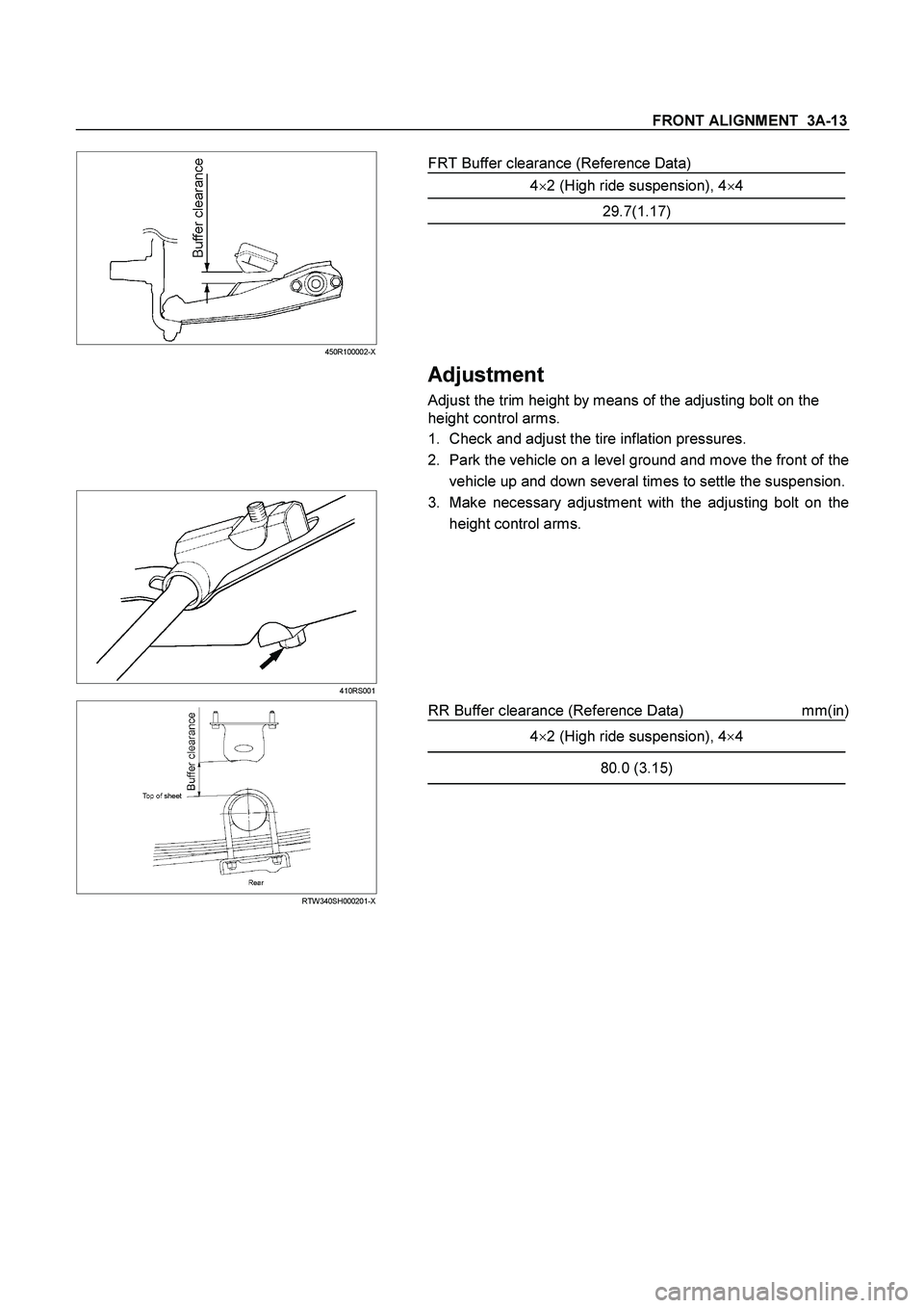
FRT Buffer clearance (Reference Data)
4�2 (High ride suspension), 4�4
29.7(1.17)
Adjustment
Adjust the trim height by means of the adjusting bolt on the
height control arms.
1. Check and adjust the tire inflation pressures.
2. Park the vehicle on a level ground and move the front of the
vehicle up and down several times to settle the suspension.
410RS001
3. Make necessary adjustment with the adjusting bolt on the
height control arms.
RTW340SH000201-X
RR Buffer clearance (Reference Data) mm(in)
4�
2 (High ride suspension), 4�
4
80.0 (3.15)
Page 3503 of 4264
, then tighten it to the specified
torque.
Torque: 55N
�
�� �m (5.6kg
�
�� �m/41lb ft)
3.")
FRONT SUSPENSION 3C-11
NOTE: Paint mark to be outer side of after assembly to
vehicle.
2. Install nut (2), then tighten it to the specified
torque.
Torque: 55N
�
�� �m (5.6kg
�
�� �m/41lb ft)
3. Install bolt (7) and nut (4), then tighten to the
specified torque.
Buffer clearance: 25.9 mm (1.02 in)
Torque: 137N�
�� �m (14.0kg�
�� �m/101 lb ft)
NOTE: Apply oil to the thread.
NOTE: Tighten the bolt and nut with the parts in the
position shown in the illustration below.
RTW340SH001301-X
4. Install nut (6), then tighten it to the specified
torque.
Torque: 50N�
�� �m (5.1kg�
�� �m/37 lb ft)
5. Tighten the cam bolt (8) and nut (3), it to the
interim torque, then turn the cam bolt to the setting
mark applied during disassembly.
6. Install ball joint nut, then tighten it to the specified
torque with just enough additional torque to align
cotter pin holes. Install new cotter pin (5).
Torque: 147N�
�� �m (15.0kg�
�� �m/108 lb ft)
NOTE: Check the trim height. Refer to Front Alignment
Inspection and Adjustment.
7. Nut (3) tighten it to the specified torque.
Buffer clearance: 25.9 mm (1.02 in)
Torque: 186N�
�� �m (19.0kg�
�� �m/137 lb ft)
NOTE: Apply oil to the thread.
NOTE: Tighten the bolt and nut with the parts in the
position shown in the illustration below.
RTW340SH001301-X
8. Install wheel and tire assembly. Refer to wheel in
this section.
Page 3528 of 4264
3C-36 FRONT SUSPENSION
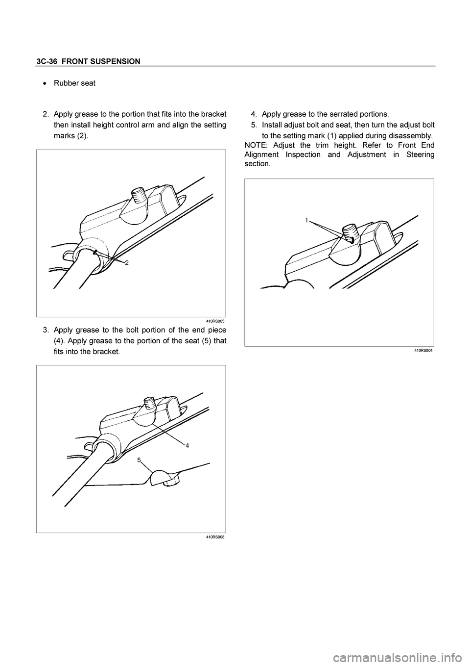
� Rubber seat
2.
Apply grease to the portion that fits into the bracket
then install height control arm and align the setting
marks (2).
410RS005
3. Apply grease to the bolt portion of the end piece
(4). Apply grease to the portion of the seat (5) that
fits into the bracket.
410RS008
4. Apply grease to the serrated portions.
5. Install adjust bolt and seat, then turn the adjust bolt
to the setting mark (1) applied during disassembly.
NOTE: Adjust the trim height. Refer to Front End
Alignment Inspection and Adjustment in Steering
section.
410RS004
Page 3531 of 4264

FRONT SUSPENSION 3C-39
Inspection and Repair
Make necessary correction or parts replacement if
wear, damage, corrosion or any other abnormal
condition are found through inspection.
Check the following parts:
�
Knuckle
�
Knuckle arm
� Thrust washer (4�4 Model Only)
Installation
1. Apply appropriate amount of multipurpose type
grease to the new bearing (Approx. 5 g) and
install needle bearing by using installer 5-8840-
2128-0 and grip 5-8840-0007-0. (4�
4 Model Only)
(4�4 Model Only)
901RW275
2. Apply multipurpose type grease to the thrust
washer, and install washer with chamfered side
facing knuckle. (4�4 Model Only)
3. Use a new oil seal, and apply multipurpose type
grease to the area surrounded by the lip (approx. 2
g). Then use installer 5-8840-2127-0 and grip 5-
8840-0007-0 to install oil seal. After fitting the oil
seal to the installer, drive it to the knuckle using a
hammer or bench press until the tool front face
contacts with the thrust washer. (4�
4 Model Only)
(4�4 Model Only)
901RW274
4. Install knuckle assembly.
5. Install upper ball joint and tighten the nut to the
specified torque, with just enough additional torque
to align cotter pin holes. Install new cotter pin (9).
Torque: 98 N�
�� �m (10.0kg�
�� �m/72 lb ft)
6. Install lower ball joint and tighten the nut to the
specified torque, with just enough additional torque
to align cotter pin holes. Install new cotter pin (2).
Torque: 147 N
�
�� �m (15.0kg
�
�� �m/108 lb ft)
7. Install back plate.
8. Install speed sensor harness.
9. Install torsion bar, refer to Torsion Bar in this
section.
NOTE: Adjust the trim height. Refer to Front End
Alignment Inspection and Adjustment in Steering.
Page 3539 of 4264
FRONT SUSPENSION 3C-47
14. Install cam plate and nut then tighten lower link nut
finger-tight.
NOTE: Apply oil to the thread.
NOTE: Tighten the nut (3) or bolt with the parts in the
position shown in the illustration below.
Buffer clearance: 29.7 mm (1.17 in)
Torque: 186 N�
�� �m (19.0kg�
�� �m/137 lb ft)
NOTE: Adjust the trim height. Refer to Front En
d
Alignment Inspection and Adjustment in Steering
section.
450R100002
 or bolt with the parts in the
position sho")