2004 ISUZU TF SERIES change time
[x] Cancel search: change timePage 1464 of 4264
6E–92 4JA1/4JH1 ENGINE DRIVEABILITY AND EMISSIONS
MISCELLANEOUS TEST
The state of each circuit can be tested by using
miscellaneous test menus. Especially when DTC
cannot be detected, a faulty circuit can be diagnosed by
testing each circuit by means of these menus.
Even DTC has been detected, the circuit tests using
these menus could help discriminate between a
mechanical trouble and an electrical trouble.
Connect Tech 2 and select "Powertrain", "4JA1-TC
Bosch" or "4JH1-TC Bosch" & "Miscellaneous Test".
F0: Lamps
F0: Glow Time Telltale Test
When the Tech 2 is operated, "Glow Time Indicator
Lamp" is turned on or off.
The circuit is correct if the "Glow Time Indicator Lamp"
in the instrument panel is turned on or off in accordance
with this operation.
F1: Relays
F0: Glow Time Relay Test
When the Tech 2 is operated, glow relay turns ON or
OFF.
The circuit is correct if glow relay is operated in
accordance with this operation.
F2: Solenoids
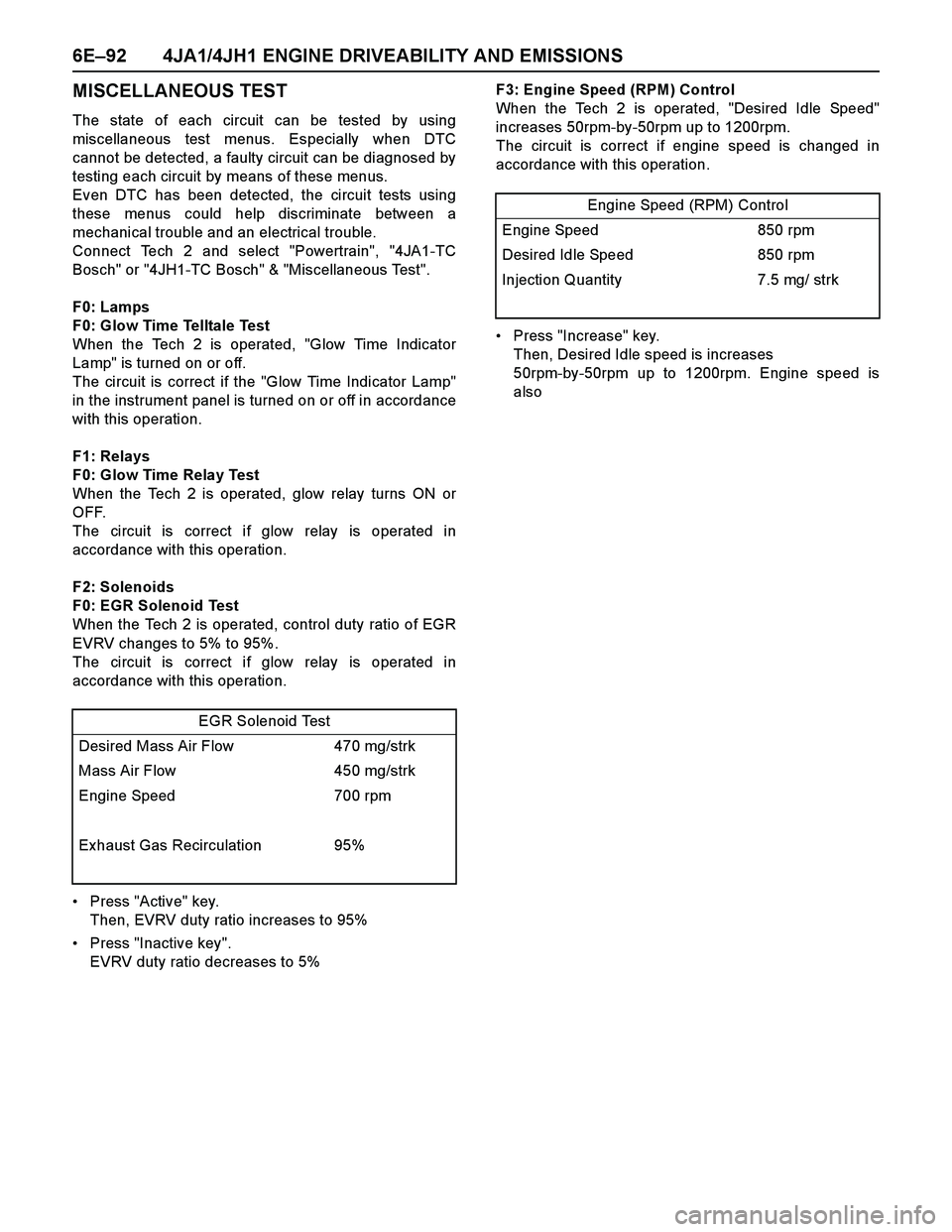
F0: EGR Solenoid Test
When the Tech 2 is operated, control duty ratio of EGR
EVRV changes to 5% to 95%.
The circuit is correct if glow relay is operated in
accordance with this operation.
Press "Active" key.
Then, EVRV duty ratio increases to 95%
Press "Inactive key".
EVRV duty ratio decreases to 5%F3: Engine Speed (RPM) Control
When the Tech 2 is operated, "Desired Idle Speed"
increases 50rpm-by-50rpm up to 1200rpm.
The circuit is correct if engine speed is changed in
accordance with this operation.
Press "Increase" key.
Then, Desired Idle speed is increases
50rpm-by-50rpm up to 1200rpm. Engine speed is
also
EGR Solenoid Test
Desired Mass Air Flow 470 mg/strk
Mass Air Flow 450 mg/strk
Engine Speed 700 rpm
Exhaust Gas Recirculation 95%
Engine Speed (RPM) Control
Engine Speed 850 rpm
Desired Idle Speed 850 rpm
Injection Quantity 7.5 mg/ strk
Page 1469 of 4264
![ISUZU TF SERIES 2004 Workshop Manual 4JA1/4JH1 ENGINE DRIVEABILITY AND EMISSIONS 6E–97
After recording the snapshot in Tech2, transfer the data
from Tech2 to PC by the below procedures.
1. Start TIS2000.
2. Select [Snapshot Upload] on ISUZU TF SERIES 2004 Workshop Manual 4JA1/4JH1 ENGINE DRIVEABILITY AND EMISSIONS 6E–97
After recording the snapshot in Tech2, transfer the data
from Tech2 to PC by the below procedures.
1. Start TIS2000.
2. Select [Snapshot Upload] on](/manual-img/61/57180/w960_57180-1468.png)
4JA1/4JH1 ENGINE DRIVEABILITY AND EMISSIONS 6E–97
After recording the snapshot in Tech2, transfer the data
from Tech2 to PC by the below procedures.
1. Start TIS2000.
2. Select [Snapshot Upload] on the TIS2000 start
screen.
3. Select [Upload from trouble diagnosis tool (transfer
from diagnosis tester)] or click the corresponding
icon of the tool bar.
4. Select Tech2, and transfer the recorded snapshot
information.
5. Select the transferred snapshot.
6. After ending transfer of the snapshot, data
parameter list is displayed on the screen.3. Snapshot data is displayed with TIS2000
[Snapshot Upload] function.
Snapshot is stored in the PC hard disk or floppy disk,
and can be displayed any time.
Stored snapshot can be displayed by the below
procedures.
1. Start TIS2000.
2. Select [Snapshot Upload] on the TIS2000 start
screen.
3. Select [Open the existing files] or click the
corresponding icon of the tool bar.
4. Select the transferred snapshot.
5. Open the snapshot, to display the data parameter
list on the screen.
Graph display Values and graphs (Max. 3 graphs):
1. Click the icon for graph display. [Graph Parameter]
window opens.
2. Click the first graph icon of the window upper part,
and select one parameter from the list of the window
lower part. Selected parameter is displayed nest to
the graph icon. Graph division can be selected in
the field on the parameter right side.
3. Repeat the same procedures with the 2nd and 3rd
icons.
4. After selecting all parameters to be displayed (Max .
3 parameters), click [OK] button.
5. Parameter selected is displayed in graph form on
the right of the data parameter on the screen.
6. Graph display can be moved with the navigation
icon.
7. For displaying another parameter by graph, click the
parameter of the list, drug the mouse to the display
screen while pressing the mouse button and release
the mouse button. New parameter is displayed at
the position of the previous parameter. For
displaying the graph display screen in full size,
move the cursor upward on the screen. When thecursor is changed to the magnifying glass form, click
the screen. Graph screen is displayed on the whole
screen.
Page 1472 of 4264
6E–100 4JA1/4JH1 ENGINE DRIVEABILITY AND EMISSIONS
2. Demand of Data
1. Connect Tech-2 to the vehicle. When activated by
turning on the power of Tech-2, push the “Enter”
switch.
2. Turn on the ignition switch (without starting the
engine)
3. In the main menu of Diagnostic Tester, push “F1:
Service Programming System (SPS)”.
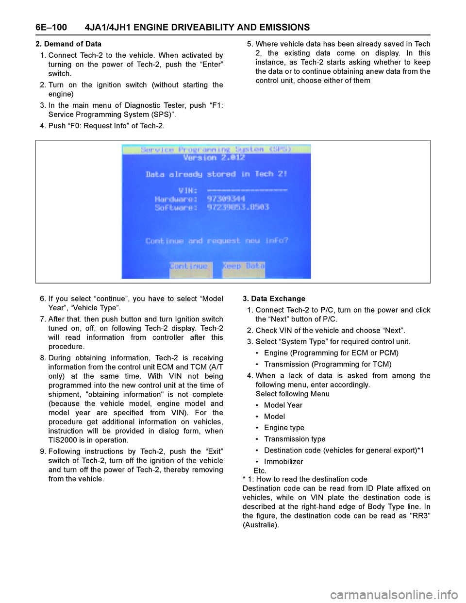
4. Push “F0: Request Info” of Tech-2.5. Where vehicle data has been already saved in Tech
2, the ex isting data come on display. In this
instance, as Tech-2 starts asking whether to keep
the data or to continue obtaining anew data from the
control unit, choose either of them
6. If you select “continue”, you have to select “Model
Year”, “Vehicle Type”.
7. After that. then push button and turn Ignition switch
tuned on, off, on following Tech-2 display. Tech-2
will read information from controller after this
procedure.
8. During obtaining information, Tech-2 is receiving
information from the control unit ECM and TCM (A/T
only) at the same time. With VIN not being
programmed into the new control unit at the time of
shipment, "obtaining information" is not complete
(because the vehicle model, engine model and
model year are specified from VIN). For the
procedure get additional information on vehicles,
instruction will be provided in dialog form, when
TIS2000 is in operation.
9. Following instructions by Tech-2, push the “Ex it”
switch of Tech-2, turn off the ignition of the vehicle
and turn off the power of Tech-2, thereby removing
from the vehicle.3. Data Exchange
1. Connect Tech-2 to P/C, turn on the power and click
the “Next” button of P/C.
2. Check VIN of the vehicle and choose “Next”.
3. Select “System Type” for required control unit.
Engine (Programming for ECM or PCM)
Transmission (Programming for TCM)
4. When a lack of data is asked from among the
following menu, enter accordingly.
Select following Menu
Model Year
Model
Engine type
Transmission type
Destination code (vehicles for general export)*1
Immobilizer
Etc.
* 1: How to read the destination code
Destination code can be read from ID Plate affix ed on
vehicles, while on VIN plate the destination code is
described at the right-hand edge of Body Type line. In
the figure, the destination code can be read as "RR3"
(Australia).
Page 1532 of 4264
6E–160 4JA1/4JH1 ENGINE DRIVEABILITY AND EMISSIONS
DIAGNOSTIC TROUBLE CODE (DTC) P0115 (SYMPTOM CODE 1)
(FLASH CODE 14) ENGINE COOLANT TEMPERATURE SENSOR CIRCUIT
HIGH INPUT
DIAGNOSTIC TROUBLE CODE (DTC) P0115 (SYMPTOM CODE 2)
(FLASH CODE 14) ENGINE COOLANT TEMPERATURE SENSOR CIRCUIT LOW
INPUT
Condition for setting the DTC and action taken when the DTC sets
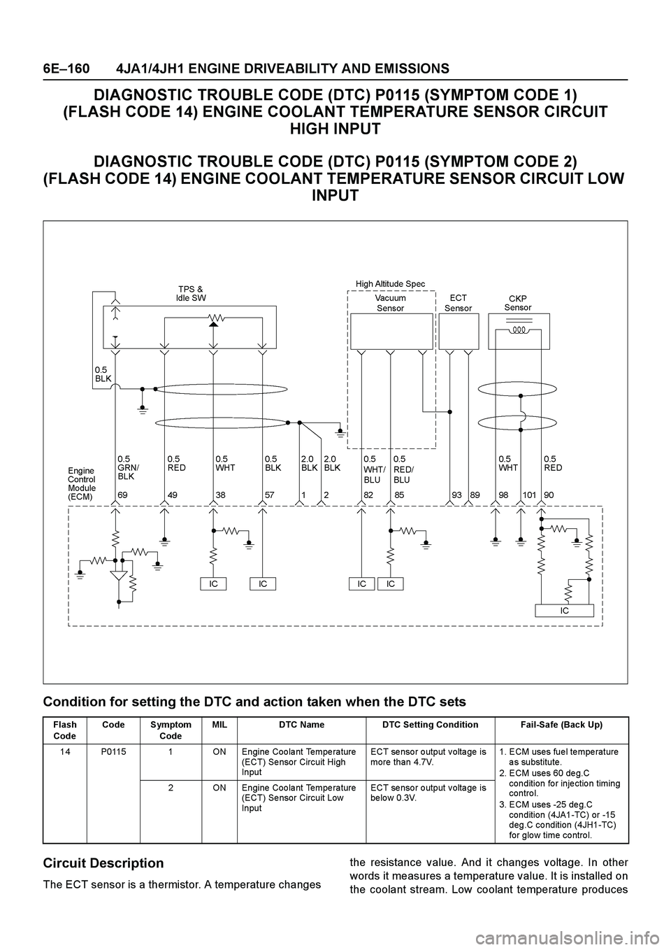
Circuit Description
The ECT sensor is a thermistor. A temperature changesthe resistance value. And it changes voltage. In other
words it measures a temperature value. It is installed on
the coolant stream. Low coolant temperature produces
Flash
CodeCode Symptom
CodeMIL DTC Name DTC Setting Condition Fail-Safe (Back Up)
14 P0115 1 ON Engine Coolant Temperature
(ECT) Se nsor Circuit High
InputECT sensor output voltage is
more than 4.7V.1. ECM uses fue l te mpe rature
as substitute.
2. ECM uses 60 de g.C
condition for injection timing
contro l.
3. ECM uses -25 de g.C
condition (4JA1-TC) or -15
deg.C condition (4JH1-TC)
for glo w time co ntro l. 2 ON Engine Coolant Temperature
(ECT) Se nsor Circuit Low
InputECT sensor output voltage is
be lo w 0.3V.
Page 1551 of 4264
4JA1/4JH1 ENGINE DRIVEABILITY AND EMISSIONS 6E–179
Circuit Description
The ECM is calculates an injection quantity and an
injection timing using the various sensors (crankshaft
position sensor, camshaft position sensor, engine
coolant temperature sensor, etc.). The timing control
valve (TCV) operation performs an injection timing
decision.
The TCV performs as a variable throttle, using the rapid
opening and closing cycle of the valve needle in the
TCV.
The TCV is assembled in the injection pump. The signal
of desired injection timing and actual injection timing are
ex changed via the CAN-bus between the PSG and
ECM.
If the timer position is out of tolerance (deviation or
fluctuation), DTC P0216 will be stored.
Diagnostic Aids
An intermittent may be caused by the following:
Poor connections.
Misrouted harness.
Rubbed through wire insulation.
Broken wire inside the insulation.
Insufficient air bleeding of fuel line.
Low fuel quantity in the fuel tank.
Check for the following conditions:
Insufficient air bleeding of fuel line inside, clogged
fuel filter or pinched fuel pipe/hose may cause the
DTC store or improper engine performance.Air bleeding procedure:
1.Operate the priming pump until strong resistance is
felt.
2.Wait 1 minute, and operate the priming pump until
strong resistance is felt.
3.Wait 1 minute, and operate the priming pump until
strong resistance is felt.
4.Turn the ignition switch to the "ON" position. Wait
until the glow indicator lamp turns off.
5.Turn the ignition switch to the "START" position and
crank the engine until it starts.
6.If the engine does not start, repeat Step 3 - 5.
7.Allow the engine to idle for 3 minutes to bleed air
completely form the fuel system and check for fuel
leakage.
Poor connection at ECM and PSG-Inspect harness
connectors for backed out terminals, improper
mating, broken locks, improperly formed or damaged
terminals, and poor terminal to wire connection.
Damaged harness-Inspect the wiring harness for
damage. If the harness appears to be OK, observe
the "Actual Injection Start" display on the Tech2 while
moving connectors and wiring harness related to the
sensor.
Page 1733 of 4264
4JA1/4JH1 ENGINE DRIVEABILITY AND EMISSIONS 6E–361
SYMPTOM DIAGNOSIS
PRELIMINARY CHECKS
Before using this section, perform the “On-Board
Diagnostic (OBD) System Check” and verify all of the
following items:
The engine control module (ECM) and check engine
lamp (MIL=malfunction indicator lamp are operating
correctly.
There are no Diagnostic Trouble Code(s) stored.
Tech 2 data is within normal operating range. Refer to
Typical Scan Data Values.
Verify the customer complaint and locate the correct
symptom in the table of contents. Perform the
procedure included in the symptom chart.
VISUAL/PHYSICAL CHECK
Several of the symptom procedures call for a careful
visual/physical check. This can lead to correcting a
problem without further checks and can save valuable
time. This check should include the following items:
ECM grounds for cleanliness, tightness and proper
location.
Vacuum hoses for splits, kinks, and proper
connection. Check thoroughly for any type of leak or
restriction.
Air intake ducts for collapsed or damaged areas.
Air leaks at throttle body mounting area, mass air flow
(MAF) sensor and intake manifold sealing surfaces.
Wiring for proper connections, pinches and cuts.
INTERMITTENT
Important: An intermittent problem may or may not turn
on the check engine lamp (MIL=malfunction indicator
lamp) or store a Diagnostic Trouble Code. Do NOT use
the Diagnostic Trouble Code (DTC) charts for
intermittent problems.
The fault must be present to locate the problem.
Most intermittent problems are cased by faulty electrical
connections or wiring. Perform a careful visual/physical
check for the following conditions.
Poor mating of the connector halves or a terminal not
fully seated in the connector (backed out).
Improperly formed or damaged terminal.
All connector terminals in the problem circuit should
be carefully checked for proper contact tension.
Poor terminal-to-wire connection. This requires
removing the terminal form the connector body to
check.
Check engine lamp (MIL=malfunction indicator lamp)
wire to ECM shorted to ground.
Poor ECM grounds. Refer to the ECM wiring
diagrams.Road test the vehicle with a Digital Multimeter
connected to a suspected circuit. An abnormal voltage
when the malfunction occurs is a good indication that
there is a fault in the circuit being monitored.
Using Tech 2 to help detect intermittent conditions. The
Tech 2 have several features that can be used to
located an intermittent condition. Use the following
features to find intermittent faults:
To check for loss of diagnostic code memory,
disconnect the MAF sensor and idle the engine until the
check engine lamp (MIL=malfunction indicator lamp)
comes on. Diagnostic Trouble Code P0100 should be
stored and kept in memory when the ignition is turned
OFF.
If not, the ECM is faulty. When this test is completed,
make sure that you clear the Diagnostic Trouble Code
P0100 from memory.
An intermittent check engine lamp (MIL=malfunction
indicator lamp) with no stored Diagnostic Trouble Code
may be caused by the following:
Check engine lamp (MIL=malfunction indicator lamp)
wire to ECM short to ground.
Poor ECM grounds. Refer to the ECM wiring
diagrams.
Check for improper installation of electrical options such
as light, cellular phones, etc. Check all wires from ECM
to the ignition control module for poor connections.
Check for an open diode across the A/C compressor
clutch and check for other open diodes (refer to wiring
diagrams in Electrical Diagnosis).
If problem has not been found, refer to ECM connector
symptom tables.
Check the “Broadcast Code” of the ECM, and
compare it with the latest Isuzu service bulletins and/
or Isuzu EEPROM reprogramming equipment to
determine if an update to the ECM's reprogrammable
memory has been released.
This identifies the contents of the reprogrammable
software and calibration contained in the ECM.
If the “Broadcast Code” is not the most current
available, it is advisable to reprogram the ECM's
EEPROM memory, which may either help identify a
hard-to find problem or may fix the problem.
The Service Programming System (SPS) will not allow
incorrect software programming or incorrect calibration
changes.
Page 1837 of 4264
ENGINE MECHANICAL (6VE1 3.5L) 6A-13
Troubleshooting Procedure
Abnormal noise stops when the spark plug on the
cylinder with defective part is shorted out.
Symptom Possible Cause Action
Piston and cylinder noise
(Faulty piston or cylinder usually
makes a combined mechanical
thumping noise which increases
when engine is suddenly accelerated
but diminishes gradually as the
engine warms up) Piston clearance increased due to
cylinder wear Replace piston and cylinder body
Piston seized Replace piston and cylinder body
Piston ring broken Replace piston and cylinder body
Piston defective Replace pistons and others
Troubleshooting Procedure
Short out each spark plug and listen for change in
engine noise.
Symptom Possible Cause Action
Piston pin noise
(Piston makes noise each time it
goes up and down) Piston pin or piston pin hole worn Replace piston, piston pin and
connecting rod assembly
Page 1937 of 4264
ENGINE COOLING (6VE1 3.5L) 6B-13
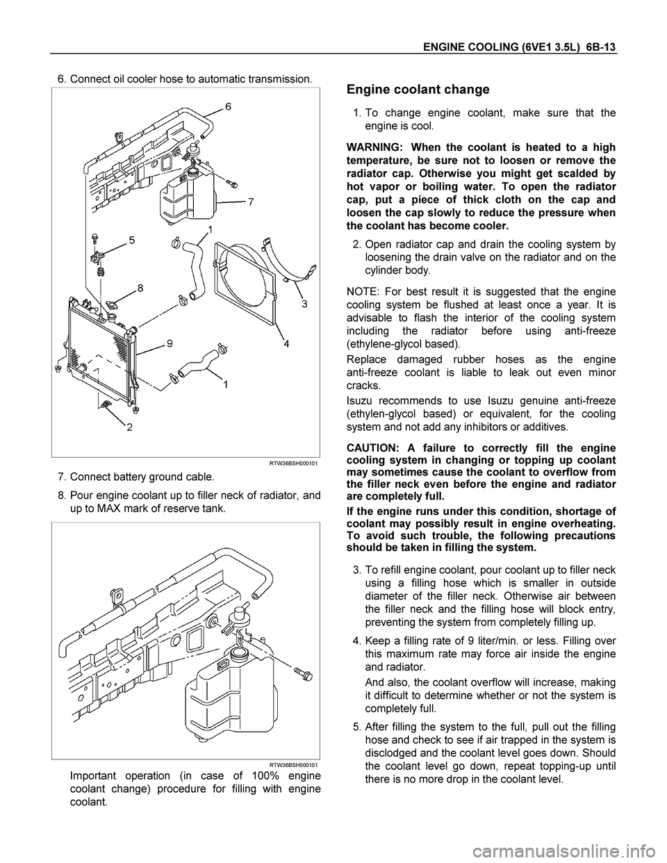
6. Connect oil cooler hose to automatic transmission.
RTW36BSH000101
7. Connect battery ground cable.
8. Pour engine coolant up to filler neck of radiator, and
up to MAX mark of reserve tank.
RTW36BSH000101
Important operation (in case of 100% engine
coolant change) procedure for filling with engine
coolant.
Engine coolant change
1. To change engine coolant, make sure that the
engine is cool.
WARNING: When the coolant is heated to a high
temperature, be sure not to loosen or remove the
radiator cap. Otherwise you might get scalded by
hot vapor or boiling water. To open the radiato
r
cap, put a piece of thick cloth on the cap and
loosen the cap slowly to reduce the pressure when
the coolant has become cooler.
2. Open radiator cap and drain the cooling system by
loosening the drain valve on the radiator and on the
cylinder body.
NOTE: For best result it is suggested that the engine
cooling system be flushed at least once a year. It is
advisable to flash the interior of the cooling system
including the radiator before using anti-freeze
(ethylene-glycol based).
Replace damaged rubber hoses as the engine
anti-freeze coolant is liable to leak out even mino
r
cracks.
Isuzu recommends to use Isuzu genuine anti-freeze
(ethylen-glycol based) or equivalent, for the cooling
system and not add any inhibitors or additives.
CAUTION: A failure to correctly fill the engine
cooling system in changing or topping up coolant
may sometimes cause the coolant to overflow from
the filler neck even before the engine and radiato
r
are completely full.
If the engine runs under this condition, shortage o
f
coolant may possibly result in engine overheating.
To avoid such trouble, the following precautions
should be taken in filling the system.
3. To refill engine coolant, pour coolant up to filler neck
using a filling hose which is smaller in outside
diameter of the filler neck. Otherwise air between
the filler neck and the filling hose will block entry,
preventing the system from completely filling up.
4. Keep a filling rate of 9 liter/min. or less. Filling ove
r
this maximum rate may force air inside the engine
and radiator.
And also, the coolant overflow will increase, making
it difficult to determine whether or not the system is
completely full.
5.
After filling the system to the full, pull out the filling
hose and check to see if air trapped in the system is
disclodged and the coolant level goes down. Should
the coolant level go down, repeat topping-up until
there is no more drop in the coolant level.