Page 182 of 4264
4B-18 REAR AXLE
17.
Install brake pipe and ABS sensor and tighten it to
the specified torque.
Torque :
ABS Sensor
8 N�
m (0.8 kg�
m/69 lb�
ft)
Brake Pipe
16 N�
m (1.6 kg�
m/12 lb�
ft)
420R30003
18.
Bleed brake pipe at the wheel cylinder. (Refer to
the section “Power-assisted Brake System”)
19.
Install brake drum.
�
Install propeller shaft. (Refer to Section “Rear
Propeller Shaft”.)
�
Refill differential oil.
�
Install wheel and tire.
�
Lower vehicle.
Page 207 of 4264
REAR AXLE 4B-43
TROUBLESHOOTING
Refer to this Section to quickly diagnose and repair
rear axle problems.
Each troubleshooting chart has three headings
arranged from left to right.
(1) Checkpoint
(2) Trouble Cause
(3) Countermeasure
This Section is divided into five sub-sections:
1. Abnormal Rear Axle Noise
1) Noise when the engine is driving the vehicle
2) Noise when the vehicle is coasting
3) Intermittent noise
4) Noise when the vehicle is turning
5) Constant noise
2. Vibration
3. Oil Leakage
1) Differential carrier leakage
2) Axle case leakage
3) Axle case to inside hub leakage
4) Axle case to inside brake drum leakage
4. Power Not Being Transmitted to the Wheels
(Propeller Shaft Operation is Normal)
Page 216 of 4264
4B-52 REAR AXLE
3) Axle Case to Inside Brake Drum Leakage
Checkpoint Trouble Cause Countermeasure
Replace the oil sealWorn or defective oil seal NGOil seal
Page 235 of 4264

FRONT WHEEL DRIVE 4C1-15
Removal
1. Jack up the vehicle and support it using jack stand.
2. Remove the tire and wheel.
3. Remove the stone guard.
4. Remove the brake caliper fixing bolt and hang the caliper.
Refer to Disc Brakes in Brake section.
5. Remove the antilock brake system speed sensor.
Refer to Front Wheel Speed Sensor in Brake section.
6. Remove the hub and disc assembly.
Refer to Front Hub and Disc in this section.
7. Remove the propeller shaft, refer to Front Propeller Shaft in
this section.
8. Loosen the height control arm of the torsion bar, then
remove the torsion bar from lower control arm.
Refer to Torsion Bar in Suspension section.
9. Remove the suspension crossmember.
10. Remove the lower nut (1) of the stabilizer link.
11. Remove the lower bolt and nut (2) of the shock absorber.
12. Remove the tie-rod end from the knuckle.
Refer to Power Steering Unit in Steering Section.
13. Disconnect the breather hose of the front axle.
14. Disconnect the actuator connector. (With shift on the fly)
15. Remove the bolts and nuts of the lower control arm (Frame
side), then disconnect the lower control arm from frame.
16. Disconnect between the right side upper control arm and
the knuckle, then remove the knuckle with lower control
arm.
CAUTION :
When removing the knuckle, be careful not to damage the
oil seal inside of the knuckle.
Page 237 of 4264

FRONT WHEEL DRIVE 4C1-17
NOTE :
Adjust the buffer clearance before tighten the bolts and nuts of
the lower control arm.
6. Install the breather hose of the front axle.
7. Install the actuator connector of the shift on the fly. (With
shift on the fly)
8. Install the tie-rod end of the power steering unit to the
knuckle, tighten the nut to the specified torque.
Torque : 98 N·m (10.0kg·m/73 lb ft)
9. Install lower bolts and nuts of the shock absorber, tighten it
to the specified torque.
Torque : 93 N·m (9.5kg·m/69 lb ft)
10. Install lower nuts of the stabilizer link, tighten it to the
specified torque.
Torque : 50 N·m (5.1kg·m/37 lb ft)
11. Install the suspension crossmember.
12. Install the torsion bar.
Refer to Torsion Bar in Suspension section.
13. Install the front propeller shaft.
Refer to Front Propeller Shaft in this section.
14. Install the hub and disc assembly and adjust the bearing
preload.
Refer to Front Hub and Disc in this section.
15. Install the wheel speed sensor of the antilock brake
system.
16. Install the brake caliper. Tighten the bolt of the caliper
bracket to the specified torque.
Torque : 155 N·m (15.8kg·m/115 lb ft)
17. Install the stone guard.
18. Install the tire and wheel.
19. Lower the vehicle, adjust the trim height.
Refer to Trim Height Adjustment in Steering section.
20. Tighten the bolts and nuts of the lower control arm to the
specified torque.
Refer to Lower Control Arm in Suspension section.
Page 262 of 4264
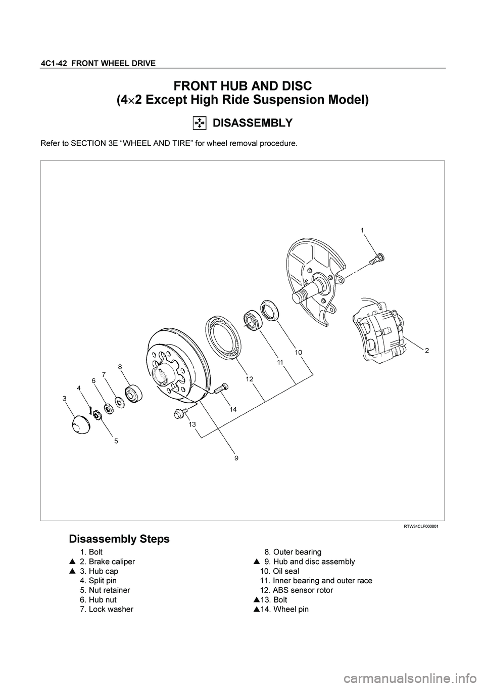
4C1-42 FRONT WHEEL DRIVE
FRONT HUB AND DISC
(4�
�� �2 Except High Ride Suspension Model)
DISASSEMBLY
Refer to SECTION 3E “WHEEL AND TIRE” for wheel removal procedure.
RTW34CLF000801
Disassembly Steps
1. Bolt
�
2. Brake caliper
�
3. Hub cap
4. Split pin
5. Nut retainer
6. Hub nut
7. Lock washer
8. Outer bearing
�
9. Hub and disc assembly
10. Oil seal
11. Inner bearing and outer race
12. ABS sensor rotor
�
13. Bolt
�
14. Wheel pin
Page 263 of 4264
FRONT WHEEL DRIVE 4C1-43
Important Operations
Before removal, jack up the front of vehicle and support frame
with jack stands.
2. Brake Caliper
(1) Remove the two bolts from the rear side of the knuckle arm,
then remove the brake caliper, with the brake hose
attached.
(2) Use a wire etc., for attaching the brake caliper to the uppe
r
link.
Refer to the section Brake.
3. Hub Cap
When removing hub cap, exercise care so as not to scratch or
distort hub fitting face.
9. Hub and Disc Assembly
Using a brass bar to remove the outer bearing outer race (1),
oil seal, inner bearing and inner bearing outer race (2) from the
hug.
If necessary, replace the wheel pin in the following manner.
13. Bolt
14. Wheel Pin ; Front Hub
(1) Scribe mark on hub to disc before disassembly to insure
proper assembly.
(2) Drive out the ABS sensor rotor using a metal bar and
hammer through the two bolt holes.
�
Discard the used ABS sensor rotor
Refer to the section Brake.
Page 265 of 4264
FRONT WHEEL DRIVE 4C1-45
INSPECTION AND REPAIR
Make necessary correction or parts replacement if wear, damage or any other abnormal conditions are found
through inspection.
For inspection and servicing of disc caliper, and relative parts, and ABS parts, refer to section 5 Brakes.
� Hub
� Hub bearing
� Bearing outer race
�
Disc
�
Oil seal
�
Knuckle spindle
�
ABS sensor rotor
�
Caliper
Visual Check
Check the following parts for wear, damage or other abnormal
conditions.

 Checkpoi")
 Axle Case to Inside Brake Drum Leakage
Checkpoint Trouble Cause Countermeasure
Replace the oil sealWorn or defective oil seal NGOil seal")
 Remove the two bolts from the rear sid")
