Page 1666 of 4264
6E–294 4JA1/4JH1 ENGINE DRIVEABILITY AND EMISSIONS
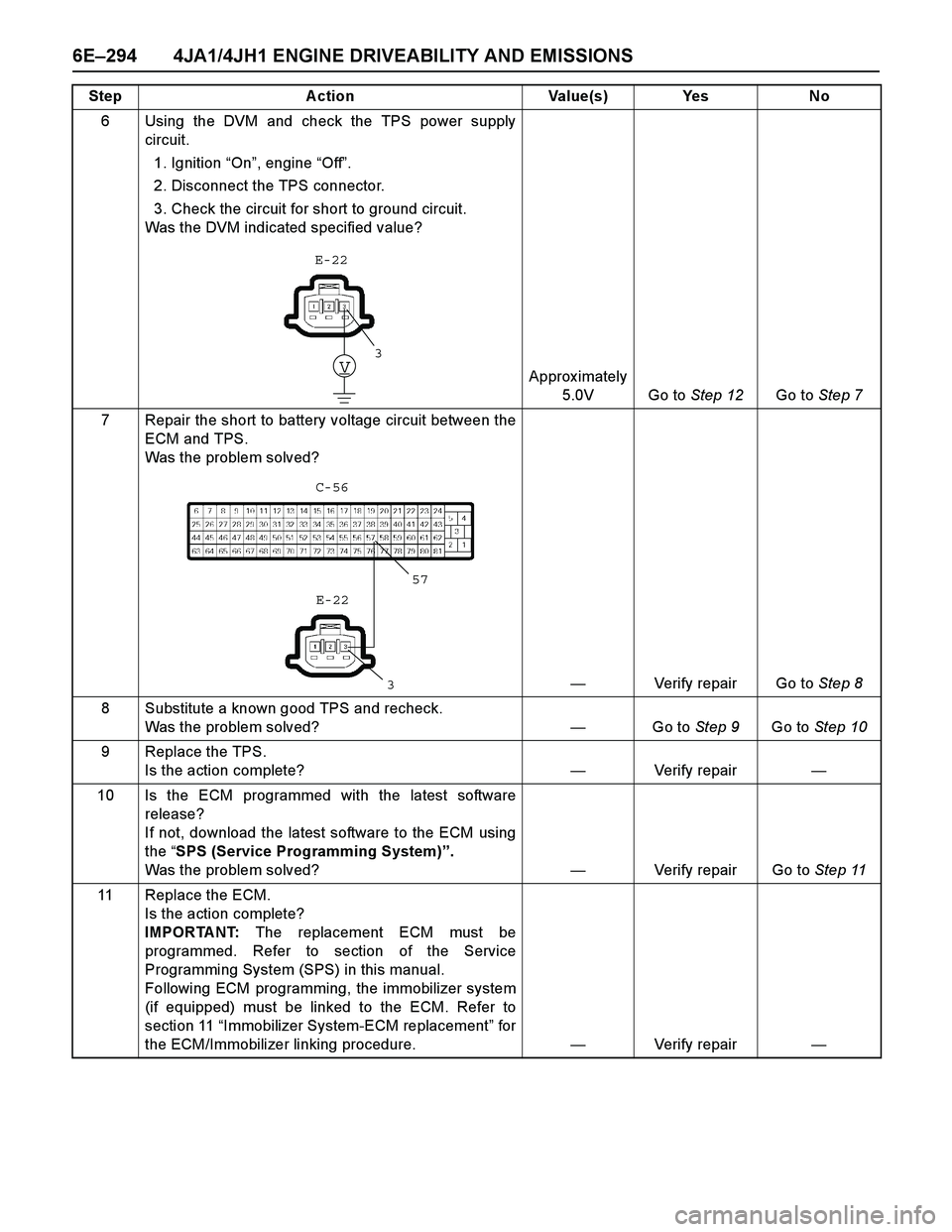
6 Using the DVM and check the TPS power supply
circuit.
1. Ignition “On”, engine “Off”.
2. Disconnect the TPS connector.
3. Check the circuit for short to ground circuit.
Was the DVM indicated specified value?
Approx imately
5.0V Go to Step 12Go to Step 7
7 Repair the short to battery voltage circuit between the
ECM and TPS.
Was the problem solved?
—Verify repair Go to Step 8
8 Substitute a known good TPS and recheck.
Was the problem solved?—Go to Step 9Go to Step 10
9 Replace the TPS.
Is the action complete?—Verify repair—
10 Is the ECM programmed with the latest software
release?
If not, download the latest software to the ECM using
the “SPS (Service Programming System)”.
Was the problem solved?—Verify repair Go to Step 11
11 Replace the ECM.
Is the action complete?
IMPORTANT: The replacement ECM must be
programmed. Refer to section of the Service
Programming System (SPS) in this manual.
Following ECM programming, the immobilizer system
(if equipped) must be linked to the ECM. Refer to
section 11 “Immobilizer System-ECM replacement” for
the ECM/Immobilizer linking procedure.—Verify repair— Step Action Value(s) Yes No
V3 E-22
57
3 C-56
E-22
Page 1790 of 4264
6E–418 4JA1/4JH1 ENGINE DRIVEABILITY AND EMISSIONS
ON-VEHICLE SERVICE PROCEDURE
ENGINE CONTROL MODULE
(ECM)
Location
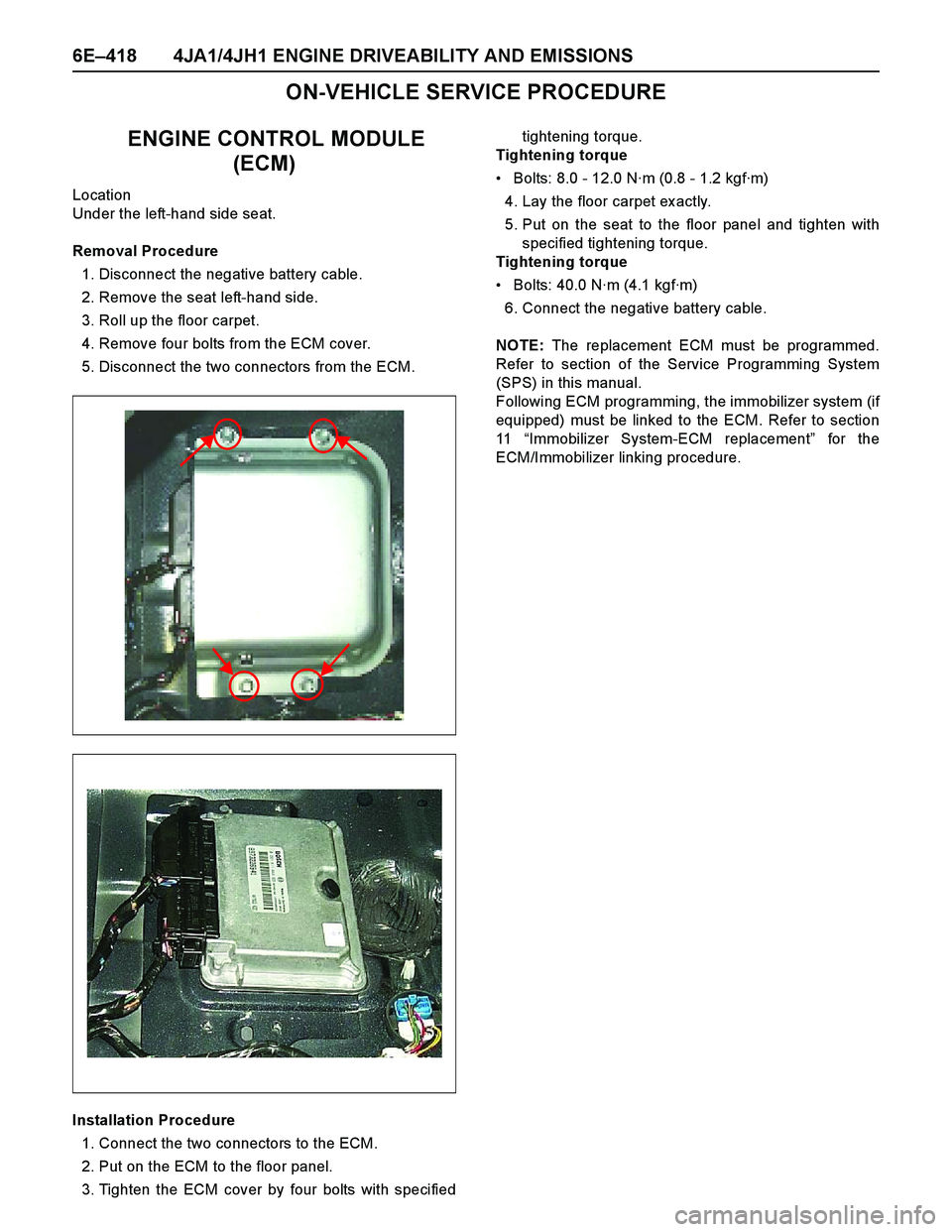
Under the left-hand side seat.
Removal Procedure
1. Disconnect the negative battery cable.
2. Remove the seat left-hand side.
3. Roll up the floor carpet.
4. Remove four bolts from the ECM cover.
5. Disconnect the two connectors from the ECM.
Installation Procedure
1. Connect the two connectors to the ECM.
2. Put on the ECM to the floor panel.
3. Tighten the ECM cover by four bolts with specifiedtightening torque.
Tightening torque
Bolts: 8.0 - 12.0 N·m (0.8 - 1.2 kgf·m)
4. Lay the floor carpet ex actly.
5. Put on the seat to the floor panel and tighten with
specified tightening torque.
Tightening torque
Bolts: 40.0 N·m (4.1 kgf·m)
6. Connect the negative battery cable.
NOTE: The replacement ECM must be programmed.
Refer to section of the Service Programming System
(SPS) in this manual.
Following ECM programming, the immobilizer system (if
equipped) must be linked to the ECM. Refer to section
11 “Immobilizer System-ECM replacement” for the
ECM/Immobilizer linking procedure.
Page 1791 of 4264
4JA1/4JH1 ENGINE DRIVEABILITY AND EMISSIONS 6E–419
CRANKSHAFT POSITION (CKP)
SENSOR
Location
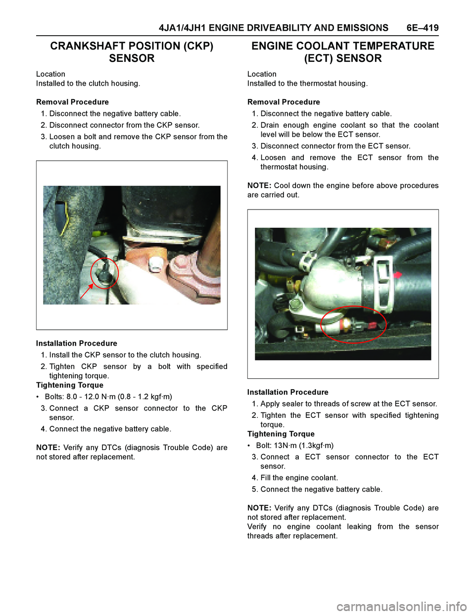
Installed to the clutch housing.
Removal Procedure
1. Disconnect the negative battery cable.
2. Disconnect connector from the CKP sensor.
3. Loosen a bolt and remove the CKP sensor from the
clutch housing.
Installation Procedure
1. Install the CKP sensor to the clutch housing.
2. Tighten CKP sensor by a bolt with specified
tightening torque.
Tightening Torque
Bolts: 8.0 - 12.0 N·m (0.8 - 1.2 kgf·m)
3. Connect a CKP sensor connector to the CKP
sensor.
4. Connect the negative battery cable.
NOTE: Verify any DTCs (diagnosis Trouble Code) are
not stored after replacement.
ENGINE COOLANT TEMPERATURE
(ECT) SENSOR
Location
Installed to the thermostat housing.
Removal Procedure
1. Disconnect the negative battery cable.
2. Drain enough engine coolant so that the coolant
level will be below the ECT sensor.
3. Disconnect connector from the ECT sensor.
4. Loosen and remove the ECT sensor from the
thermostat housing.
NOTE: Cool down the engine before above procedures
are carried out.
Installation Procedure
1. Apply sealer to threads of screw at the ECT sensor.
2. Tighten the ECT sensor with specified tightening
torque.
Tightening Torque
Bolt: 13N·m (1.3kgf·m)
3. Connect a ECT sensor connector to the ECT
sensor.
4. Fill the engine coolant.
5. Connect the negative battery cable.
NOTE: Verify any DTCs (diagnosis Trouble Code) are
not stored after replacement.
Verify no engine coolant leaking from the sensor
threads after replacement.
Page 1792 of 4264
6E–420 4JA1/4JH1 ENGINE DRIVEABILITY AND EMISSIONS
MASS AIR FLOW (MAF) & INTAKE
AIR TEMPERATURE (IAT) SENSOR
Location
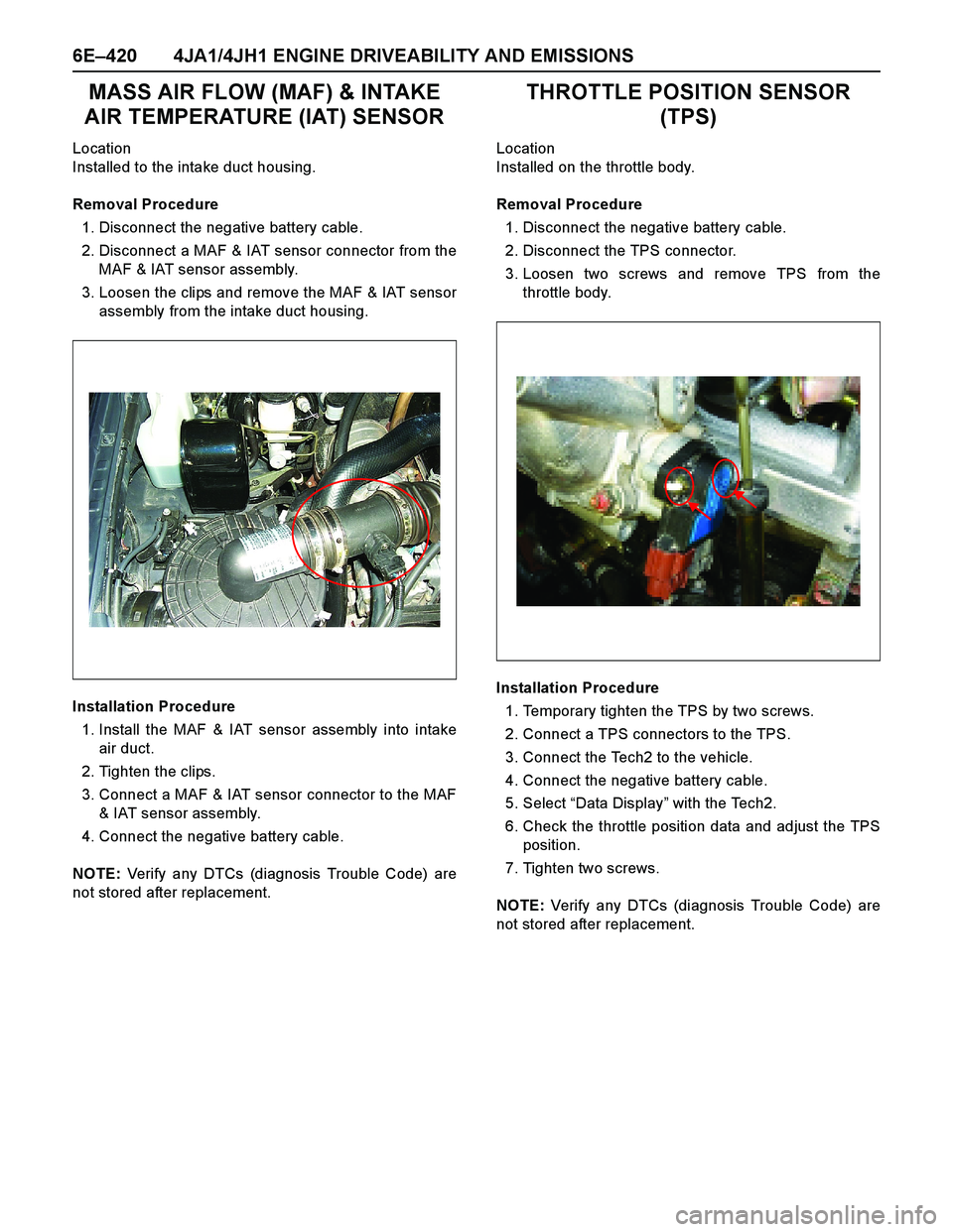
Installed to the intake duct housing.
Removal Procedure
1. Disconnect the negative battery cable.
2. Disconnect a MAF & IAT sensor connector from the
MAF & IAT sensor assembly.
3. Loosen the clips and remove the MAF & IAT sensor
assembly from the intake duct housing.
Installation Procedure
1. Install the MAF & IAT sensor assembly into intake
air duct.
2. Tighten the clips.
3. Connect a MAF & IAT sensor connector to the MAF
& IAT sensor assembly.
4. Connect the negative battery cable.
NOTE: Verify any DTCs (diagnosis Trouble Code) are
not stored after replacement.
THROTTLE POSITION SENSOR
(TPS)
Location
Installed on the throttle body.
Removal Procedure
1. Disconnect the negative battery cable.
2. Disconnect the TPS connector.
3. Loosen two screws and remove TPS from the
throttle body.
Installation Procedure
1. Temporary tighten the TPS by two screws.
2. Connect a TPS connectors to the TPS.
3. Connect the Tech2 to the vehicle.
4. Connect the negative battery cable.
5. Select “Data Display” with the Tech2.
6. Check the throttle position data and adjust the TPS
position.
7. Tighten two screws.
NOTE: Verify any DTCs (diagnosis Trouble Code) are
not stored after replacement.
Page 1793 of 4264
4JA1/4JH1 ENGINE DRIVEABILITY AND EMISSIONS 6E–421
EGR EVRV (Electrical Vacuum
Regulating Valve)
Location
Back of the air cleaner case.
Removal Procedure
1. Disconenct the negative battery cable.
2. Disconnect a EVRV connector from the EVRV.
3. Disconnect two hoses from the EVRV.
4. Loosen two bolts and remove the EVRV from the
bracket.
Installation Procedure
1. Tighten the purge solenoid by tow bolts.
2. Connect a connector to the EVRV.
3. Connect two hoses to the EVRV.
4. Connect the negative battery cable.
NOTE: Verify any DTCs (diagnosis Trouble Code) are
not stored after replacement.
Verify proper connection of two hoses.
Page 1931 of 4264
ENGINE COOLING (6VE1 3.5L) 6B-7
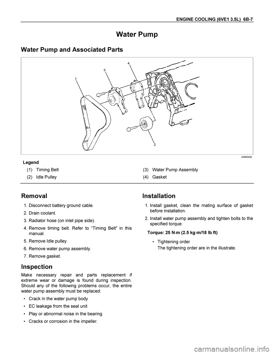
Water Pump
Water Pump and Associated Parts
030RS002
Legend
(1) Timing Belt (3) Water Pump Assembly
(2) Idle Pulley (4) Gasket
Removal
1. Disconnect battery ground cable.
2. Drain coolant.
3. Radiator hose (on inlet pipe side).
4. Remove timing belt. Refer to “Timing Belt" in this
manual.
5. Remove Idle pulley.
6. Remove water pump assembly.
7. Remove gasket.
Inspection
Make necessary repair and parts replacement if
extreme wear or damage is found during inspection.
Should any of the following problems occur, the entire
water pump assembly must be replaced:
Crack in the water pump body
EC leakage from the seal unit
Play or abnormal noise in the bearing
Cracks or corrosion in the impeller.
Installation
1. Install gasket, clean the mating surface of gasket
before installation.
2. Install water pump assembly and tighten bolts to the
specified torque.
Torque: 25 N�
�� �m (2.5 kg�
�� �m/18 lb ft)
Tightening order
The tightening order are in the illustrate.
Page 1933 of 4264
ENGINE COOLING (6VE1 3.5L) 6B-9
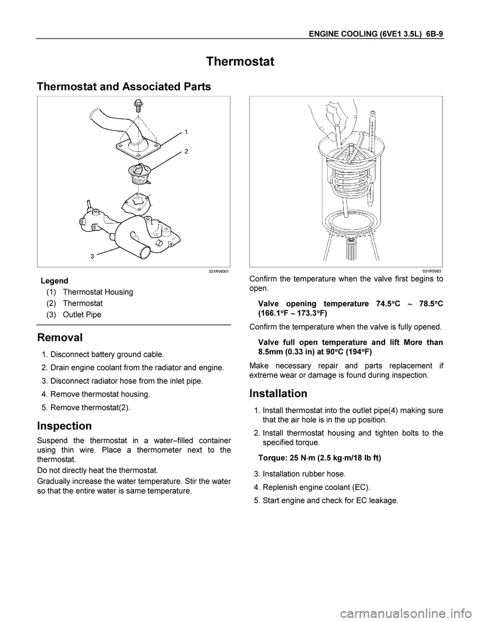
Thermostat
Thermostat and Associated Parts
031RW001
Legend
(1) Thermostat Housing
(2) Thermostat
(3) Outlet Pipe
Removal
1. Disconnect battery ground cable.
2. Drain engine coolant from the radiator and engine.
3. Disconnect radiator hose from the inlet pipe.
4. Remove thermostat housing.
5. Remove thermostat(2).
Inspection
Suspend the thermostat in a water–filled container
using thin wire. Place a thermometer next to the
thermostat.
Do not directly heat the thermostat.
Gradually increase the water temperature. Stir the wate
r
so that the entire water is same temperature.
031RS003
Confirm the temperature when the valve first begins to
open.
Valve opening temperature 74.5�
�� �C �
�� � 78.5�
�� �C
(166.1�
�� �F �
�� � 173.3�
�� �F)
Confirm the temperature when the valve is fully opened.
Valve full open temperature and lift More than
8.5mm (0.33 in) at 90�
�� �C (194�
�� �F)
Make necessary repair and parts replacement i
f
extreme wear or damage is found during inspection.
Installation
1. Install thermostat into the outlet pipe(4) making sure
that the air hole is in the up position.
2. Install thermostat housing and tighten bolts to the
specified torque.
Torque: 25 N�
�� �m (2.5 kg�
�� �m/18 lb ft)
3. Installation rubber hose.
4. Replenish engine coolant (EC).
5. Start engine and check for EC leakage.
Page 1959 of 4264
ENGINE ELECTRICAL (6VE1 3.5L) 6D1-1
ENGINE
ENGINE ELECTRICAL (6VE1 3.5L)
CONTENTS
Service Precaution................................................. 6D1-1
Battery...................................................................... 6D1-2
General Description............................................ 6D1-2
Diagnosis............................................................. 6D1-2
Battery Charging................................................. 6D1-3
Jump Starting....................................................... 6D1-3
Battery Removal.................................................. 6D1-4
Battery Installation............................................... 6D1-4
Main Data and Specifications................................ 6D1-5
Service Precaution
WARNING: THIS VEHICLE HAS A SUPPLEMENTAL
RESTRAINT SYSTEM (SRS). REFER TO THE SRS
COMPONENT AND WIRING LOCATION VIEW IN
ORDER TO DETERMINE WHETHER YOU ARE
PERFORMING SERVICE ON OR NEAR THE SRS
COMPONENTS OR THE SRS WIRING. WHEN YOU
ARE PERFORMING SERVICE ON OR NEAR THE
SRS COMPONENTS OR THE SRS WIRING, REFE
R
TO THE SRS SERVICE INFORMATION. FAILURE TO
FOLLOW WARNINGS COULD RESULT IN
POSSIBLE AIR BAG DEPLOYMENT, PERSONAL
INJURY, OR OTHERWISE UNNEEDED SRS SYSTEM
REPAIRS.
CAUTION: Always use the correct fastener in the
proper location. When you replace a fastener, use
ONLY the exact part number for that application.
ISUZU will call out those fasteners that require a
replacement after removal. ISUZU will also call out
the fasteners that require thread lockers or thread
sealant. UNLESS OTHERWISE SPECIFIED, do not
use supplemental coatings (Paints, greases, o
r
other corrosion inhibitors) on threaded fasteners or
fastener joint interfaces. Generally, such coatings
adversely affect the fastener torque and the joint
clamping force, and may damage the fastener.
When you install fasteners, use the correct
tightening sequence and specifications. Following
these instructions can help you avoid damage to
parts and systems.