Page 207 of 4264
REAR AXLE 4B-43
TROUBLESHOOTING
Refer to this Section to quickly diagnose and repair
rear axle problems.
Each troubleshooting chart has three headings
arranged from left to right.
(1) Checkpoint
(2) Trouble Cause
(3) Countermeasure
This Section is divided into five sub-sections:
1. Abnormal Rear Axle Noise
1) Noise when the engine is driving the vehicle
2) Noise when the vehicle is coasting
3) Intermittent noise
4) Noise when the vehicle is turning
5) Constant noise
2. Vibration
3. Oil Leakage
1) Differential carrier leakage
2) Axle case leakage
3) Axle case to inside hub leakage
4) Axle case to inside brake drum leakage
4. Power Not Being Transmitted to the Wheels
(Propeller Shaft Operation is Normal)
Page 217 of 4264
REAR AXLE 4B-53
4. POWER NOT BEING TRANSMITTED TO THE WHEELS
(PROPELLER SHAFT OPERATION IS NORMAL)
Checkpoint Trouble Cause Countermeasure
Replace the rear axle shaftBroken rear axle shaft NG
Replace the drive pinion and
the ring gear as a setDrive pinion and ring gearBroken drive pinion and/or ring
gear
Replace the differential gears
and/or the spiderDifferential cage gearsBroken differential cage gears
and/or spider NG NG
OK OK
Rear axle shaft
Page 223 of 4264
FRONT WHEEL DRIVE 4C1-3
MAIN DATA AND SPECIFICATIONS
FRONT AXLE AND DIFFERENTIAL
Ring gear size mm (in) 194 (7.6)
Axle tube
Type It consists of the duce, a cast iron housing and the Axle tube.
Gear type Hypoid
Gear ratio (to 1) 4.100, 4.300, 4.555, 4.777, 5125
Differential type Two pinion
Specified gear oil (APL grade) GL-5
Oil capacity liter 1.4
(US/UK gal.) (0.4/0.33)
Axle shaft type Constant velocity joint (Birfield joint type and double offset joint).
FRONT PROPELLER SHAFT mm(in)
4�
4 Model
Engine Model 4JA1-T(L) 4JA1-TC 4JH1-TC C24SE 6VE1
Transmission Type 5M/T (MUA) 5M/T
(MUA) 4A/T 5M/T
(MUA) 5M/T
(MUA) 4A/T
Front Axle 194 mm �
�
�
�
�
Outside Diameter mm 40 40 40 40 40 40
(in) (1.57) (1.57) (1.57) (1.57) (1.57) (1.57)
Inside Diameter mm 32 32 32 32 32 32
(in) (1.26) (1.26) (1.26) (1.26) (1.26) (1.26)
Length (L) mm 607 607 676 586 586 607
(in) (23.90) (23.90) (26.61) (23.07) (23.07) (23.90)
Fix Bolt Size T/F M10 M10 M10 M10 M10 M10
Axle M10 M10 M10 M10 M10 M10
Page 300 of 4264
4C2-2 SHIFT ON THE FLY SYSTEM
Shift On The Fly System
Outline of Shift on The Fly System
The shift on the fly system switches between 2 wheel
drive (2WD) and 4 wheel drive (4WD) electrically b
y
driver's pressing the 4WD switch (push button type) on
instrument panel.
This system controls below operations.
1.
Shifting the transfer front output gear (Connecting to,
and disconnecting from, front propeller shaft b
y
motor actuator).
2. Retrial of shifting the transfer front output gear.
3. Connecting front wheels to, and disconnecting them
from, the front axles by axle motor actuator.
4. Indicator on instrument panel.
5. 4WD out signal to other Electronic Hydraulic Control
Unit.
System Diagrams
RUW34BLF000201
Page 1162 of 4264
6A – 22 ENGINE MECHANICAL
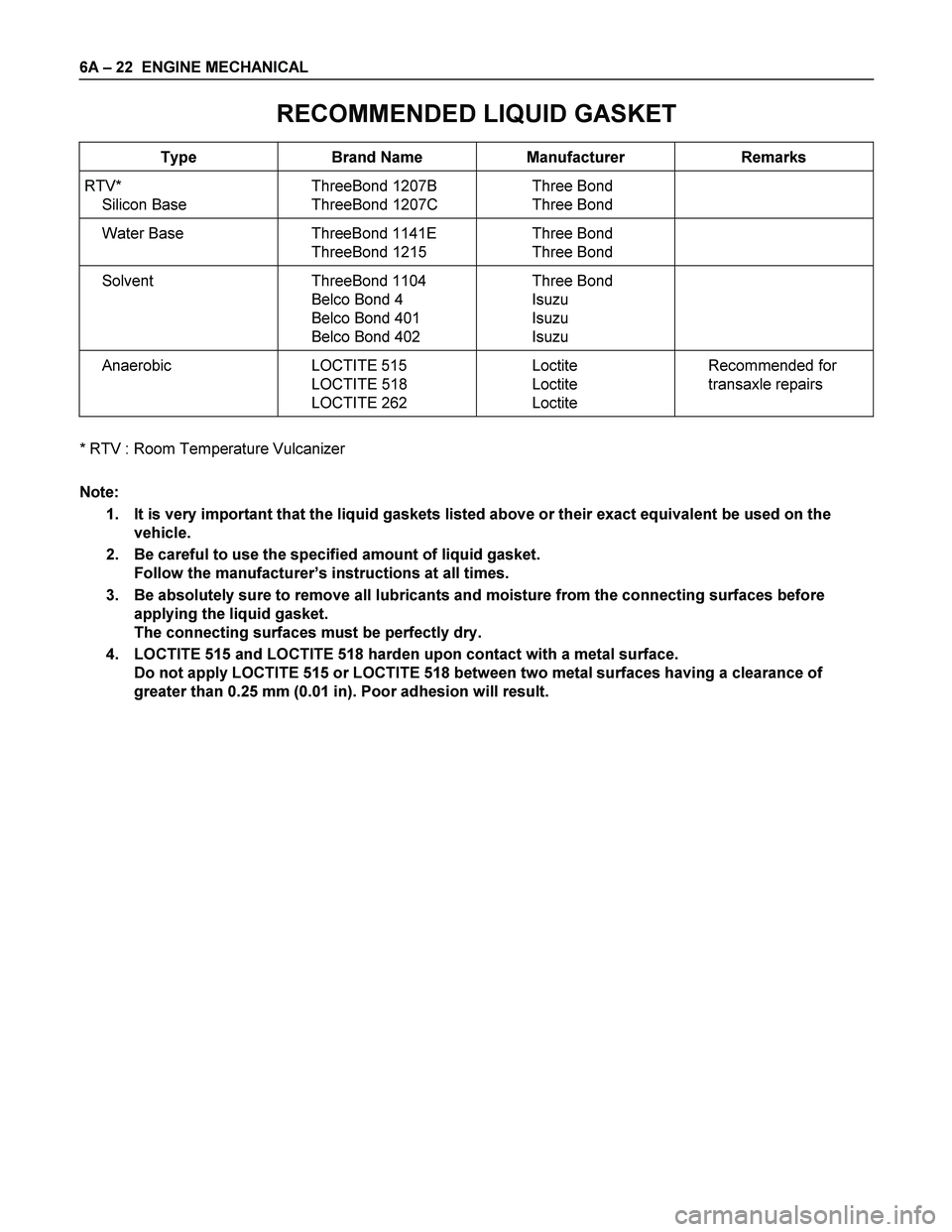
RECOMMENDED LIQUID GASKET
Type Brand Name Manufacturer Remarks
RTV*
Silicon Base ThreeBond 1207B
ThreeBond 1207C Three Bond
Three Bond
Water Base ThreeBond 1141E
ThreeBond 1215 Three Bond
Three Bond
Solvent ThreeBond 1104
Belco Bond 4
Belco Bond 401
Belco Bond 402 Three Bond
Isuzu
Isuzu
Isuzu
Anaerobic LOCTITE 515
LOCTITE 518
LOCTITE 262 Loctite
Loctite
Loctite Recommended for
transaxle repairs
* RTV : Room Temperature Vulcanizer
Note:
1. It is very important that the liquid gaskets listed above or their exact equivalent be used on the
vehicle.
2. Be careful to use the specified amount of liquid gasket.
Follow the manufacturer’s instructions at all times.
3. Be absolutely sure to remove all lubricants and moisture from the connecting surfaces before
applying the liquid gasket.
The connecting surfaces must be perfectly dry.
4. LOCTITE 515 and LOCTITE 518 harden upon contact with a metal surface.
Do not apply LOCTITE 515 or LOCTITE 518 between two metal surfaces having a clearance of
greater than 0.25 mm (0.01 in). Poor adhesion will result.
Page 1873 of 4264
ENGINE MECHANICAL (6VE1 3.5L) 6A-49
Engine Assembly
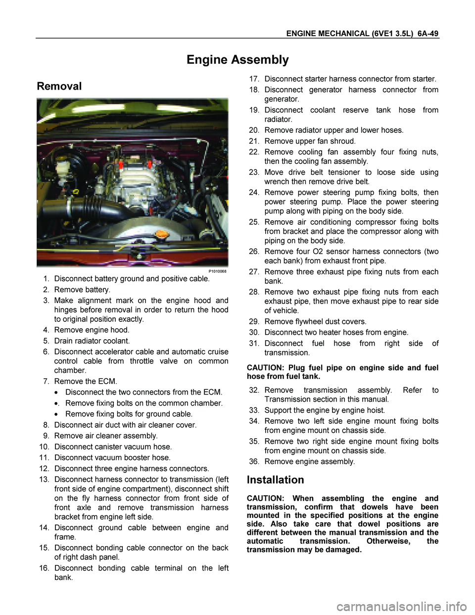
Removal
P1010068
1. Disconnect battery ground and positive cable.
2. Remove battery.
3. Make alignment mark on the engine hood and
hinges before removal in order to return the hood
to original position exactly.
4. Remove engine hood.
5. Drain radiator coolant.
6. Disconnect accelerator cable and automatic cruise
control cable from throttle valve on common
chamber.
7. Remove the ECM.
� Disconnect the two connectors from the ECM.
� . Remove fixing bolts on the common chamber.
� Remove fixing bolts for ground cable.
8. Disconnect air duct with air cleaner cover.
9. Remove air cleaner assembly.
10. Disconnect canister vacuum hose.
11. Disconnect vacuum booster hose.
12. Disconnect three engine harness connectors.
13. Disconnect harness connector to transmission (lef
t
front side of engine compartment), disconnect shift
on the fly harness connector from front side o
f
front axle and remove transmission harness
bracket from engine left side.
14. Disconnect ground cable between engine and
frame.
15. Disconnect bonding cable connector on the back
of right dash panel.
16. Disconnect bonding cable terminal on the lef
t
bank.
17. Disconnect starter harness connector from starter.
18. Disconnect generator harness connector from
generator.
19. Disconnect coolant reserve tank hose from
radiator.
20. Remove radiator upper and lower hoses.
21. Remove upper fan shroud.
22. Remove cooling fan assembly four fixing nuts,
then the cooling fan assembly.
23. Move drive belt tensioner to loose side using
wrench then remove drive belt.
24. Remove power steering pump fixing bolts, then
power steering pump. Place the power steering
pump along with piping on the body side.
25. Remove air conditioning compressor fixing bolts
from bracket and place the compressor along with
piping on the body side.
26. Remove four O2 sensor harness connectors (two
each bank) from exhaust front pipe.
27. Remove three exhaust pipe fixing nuts from each
bank.
28. Remove two exhaust pipe fixing nuts from each
exhaust pipe, then move exhaust pipe to rear side
of vehicle.
29. Remove flywheel dust covers.
30. Disconnect two heater hoses from engine.
31. Disconnect fuel hose from right side o
f
transmission.
CAUTION: Plug fuel pipe on engine side and fuel
hose from fuel tank.
32. Remove transmission assembly. Refer to
Transmission section in this manual.
33. Support the engine by engine hoist.
34. Remove two left side engine mount fixing bolts
from engine mount on chassis side.
35. Remove two right side engine mount fixing bolts
from engine mount on chassis side.
36. Remove engine assembly.
Installation
CAUTION: When assembling the engine and
transmission, confirm that dowels have been
mounted in the specified positions at the engine
side. Also take care that dowel positions are
different between the manual transmission and the
automatic transmission. Otherweise, the
transmission may be damaged.
Page 2057 of 4264
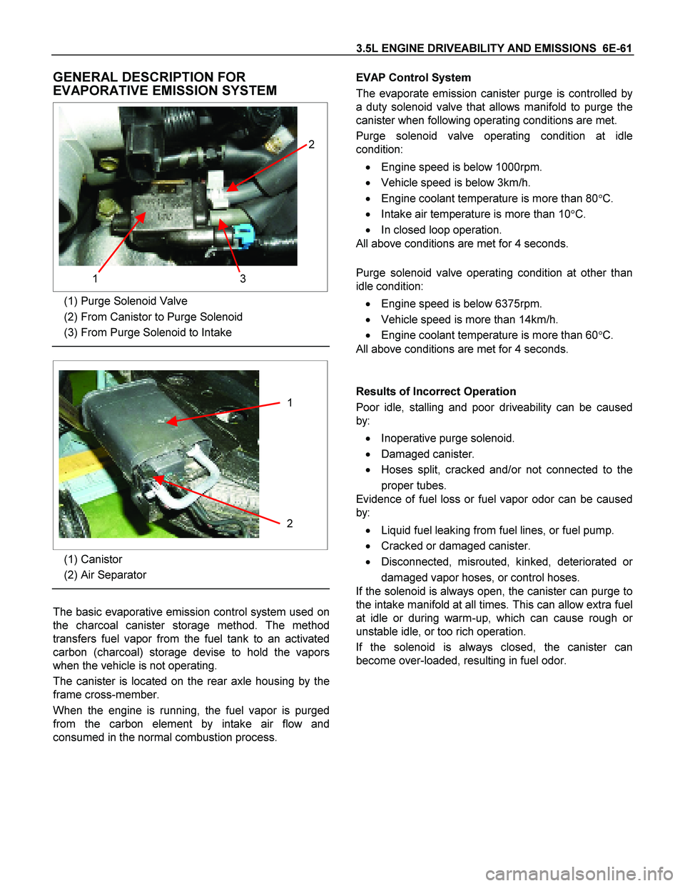
3.5L ENGINE DRIVEABILITY AND EMISSIONS 6E-61
GENERAL DESCRIPTION FOR
EVAPORATIVE EMISSION SYSTEM
3 1 2
(1) Purge Solenoid Valve
(2) From Canistor to Purge Solenoid
(3) From Purge Solenoid to Intake
1
2
(1) Canistor
(2) Air Separator
The basic evaporative emission control system used on
the charcoal canister storage method. The method
transfers fuel vapor from the fuel tank to an activated
carbon (charcoal) storage devise to hold the vapors
when the vehicle is not operating.
The canister is located on the rear axle housing by the
frame cross-member.
When the engine is running, the fuel vapor is purged
from the carbon element by intake air flow and
consumed in the normal combustion process.
EVAP Control System
The evaporate emission canister purge is controlled by
a duty solenoid valve that allows manifold to purge the
canister when following operating conditions are met.
Purge solenoid valve operating condition at idle
condition:
� Engine speed is below 1000rpm.
� Vehicle speed is below 3km/h.
� Engine coolant temperature is more than 80�C.
� Intake air temperature is more than 10�C.
� In closed loop operation.
All above conditions are met for 4 seconds.
Purge solenoid valve operating condition at other than
idle condition:
� Engine speed is below 6375rpm.
� Vehicle speed is more than 14km/h.
� Engine coolant temperature is more than 60�C.
All above conditions are met for 4 seconds.
Results of Incorrect Operation
Poor idle, stalling and poor driveability can be caused
by:
� Inoperative purge solenoid.
� Damaged canister.
� Hoses split, cracked and/or not connected to the
proper tubes.
Evidence of fuel loss or fuel vapor odor can be caused
by:
� Liquid fuel leaking from fuel lines, or fuel pump.
� Cracked or damaged canister.
� Disconnected, misrouted, kinked, deteriorated o
r
damaged vapor hoses, or control hoses.
If the solenoid is always open, the canister can purge to
the intake manifold at all times. This can allow extra fuel
at idle or during warm-up, which can cause rough o
r
unstable idle, or too rich operation.
If the solenoid is always closed, the canister can
become over-loaded, resulting in fuel odor.
Page 2978 of 4264
0A-6 GENERAL INFORMATION
IDENTIFICATION
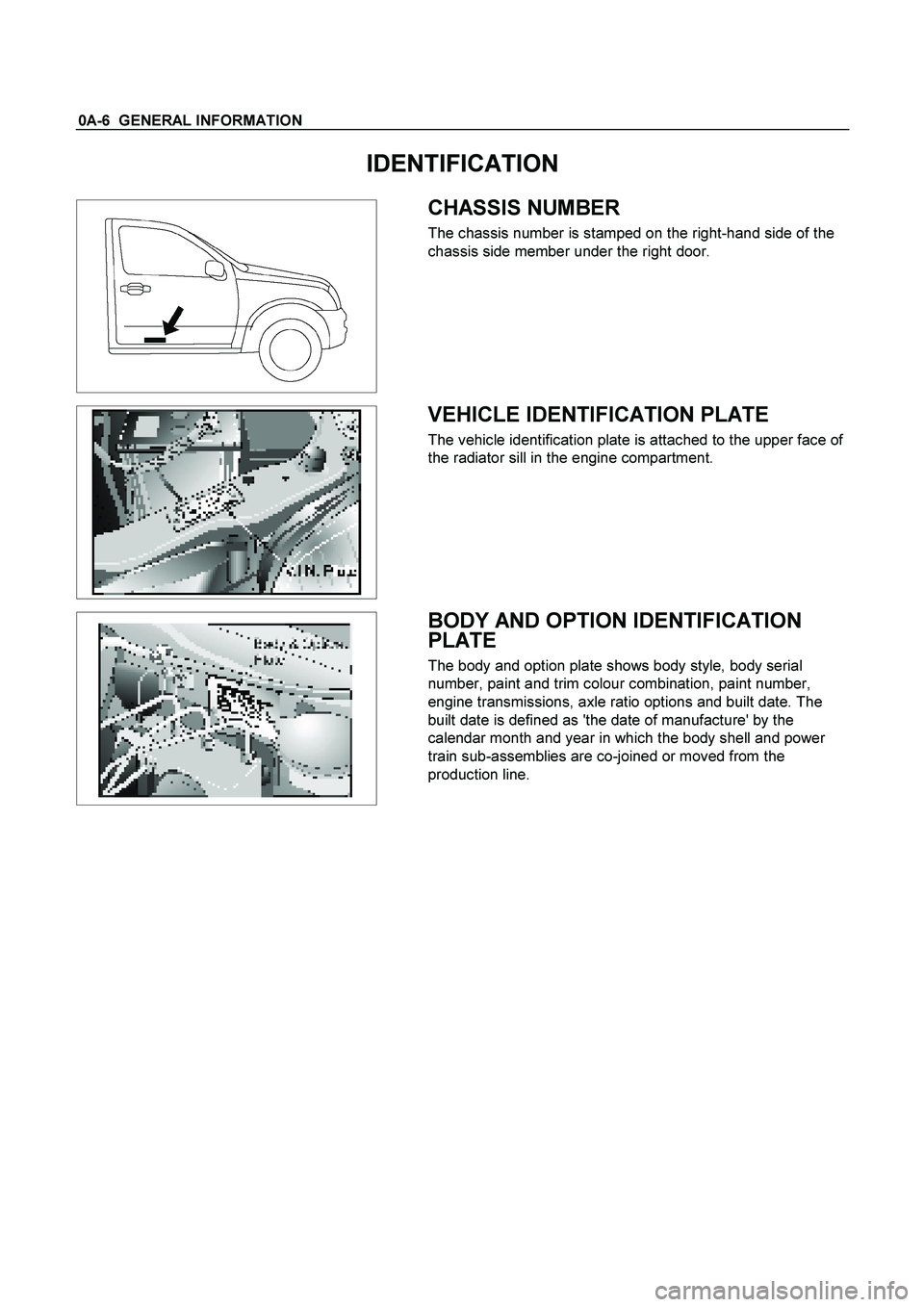
CHASSIS NUMBER
The chassis number is stamped on the right-hand side of the
chassis side member under the right door.
VEHICLE IDENTIFICATION PLATE
The vehicle identification plate is attached to the upper face of
the radiator sill in the engine compartment.
BODY AND OPTION IDENTIFICATION
PLATE
The body and option plate shows body style, body serial
number, paint and trim colour combination, paint number,
engine transmissions, axle ratio options and built date. The
built date is defined as 'the date of manufacture' by the
calendar month and year in which the body shell and power
train sub-assemblies are co-joined or moved from the
production line.