Page 612 of 4264
7C-10 CLUTCH
4JA1T(L)
RTW47CMF000101
4JA1TC/4JH1TC
Page 615 of 4264
CLUTCH 7C-13
4JA1T(L)
RTW47CMF000401
4JA1TC/4JH1TC
Page 624 of 4264
7C-22 CLUTCH
Important Operations - Removal
1. Transmission Assembly
Refer to “MANUAL TRANSMISSION” of section 7B and 7B1
for “REMOVAL AND INSTALLATION” procedure.
2. Clutch Pressure Plate Assembly
3. Driven Plate Assembly
(1) Use the clutch pilot aligner
1 to prevent the driven plate
assembly
2 from falling free.
Clutch Pilot Aligner : 5-85253-001-0
(2) Loosen the clutch cover bolts in the numerical order shown
in the illustration.
(3) Remove the pressure plate assembly
3 from the flywheel.
(4) Remove the driven plate from the flywheel.
201RS017
220RW088-X
4. Release Bearing (6VE1)
5. Shift Fork (6VE1)
(1) Remove the release bearing (1) from the transmission
case.
(2) Remove the shift fork snap pin (2).
(3) Remove the shift fork pin and shift fork (3) from the fulcrum
bridge.
6VE1 4JH1-TC, C24SE
Page 627 of 4264
CLUTCH 7C-25
(4) Clean the pressure plate surfaces.
(5) Align the pressure plate assembly
4 with the flywheel
knock pin
5.
(6) Install the pressure plate assembly to the flywheel.
(7) Tighten the clutch cover bolts a little at a time in the
numerical order shown in the illustration.
Clutch Cover Bolt Torque N�
m (kgf�
m/lb�
ft)
18 �
3 (1.8 �
0.3 / 13.0 �
2.2)
201RS017
(8) Remove the clutch pilot aligner.
Note:
Do not strike the clutch pilot aligner with a hammer to
remove it.
4JH1-TC, C24SE
6VE1
Page 629 of 4264

CLUTCH 7C-27
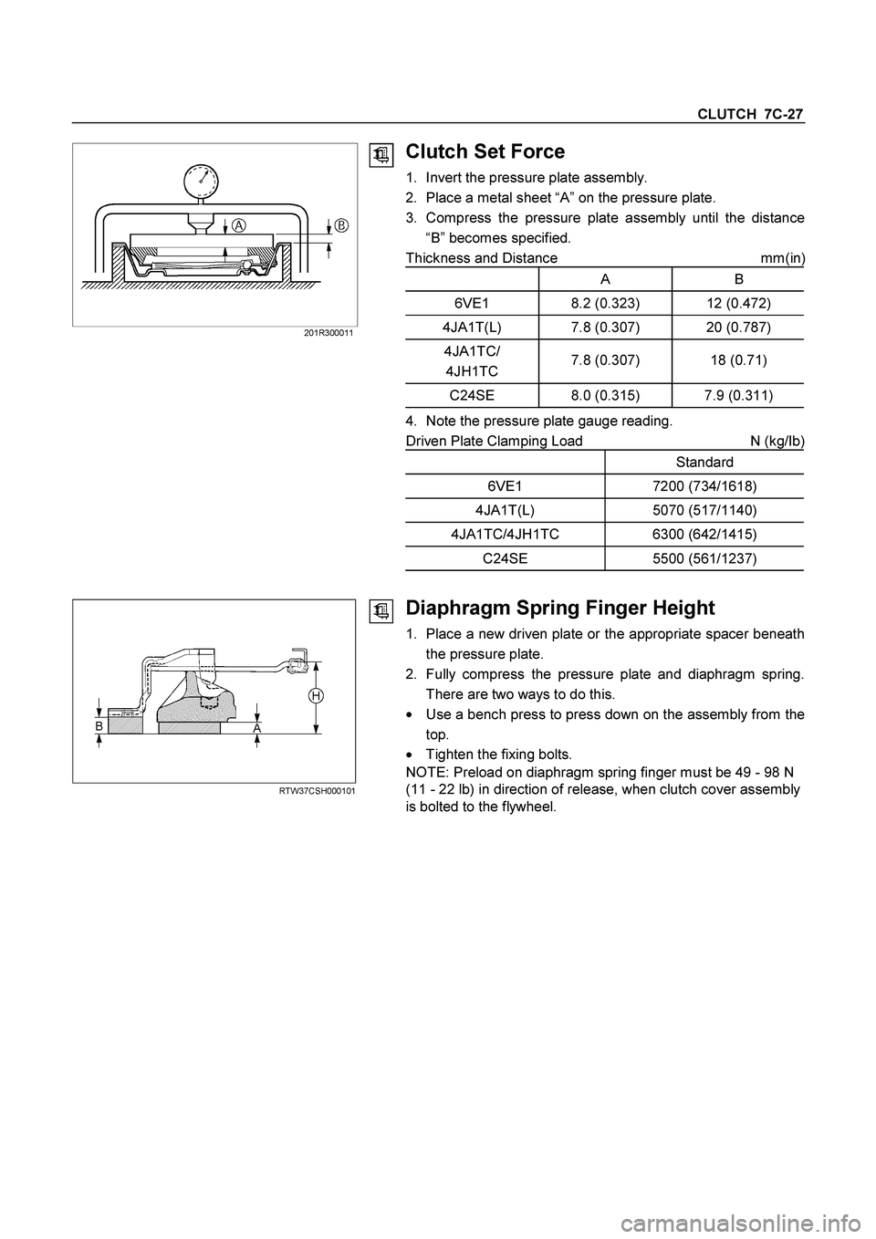
201R300011
Clutch Set Force
1. Invert the pressure plate assembly.
2. Place a metal sheet “A” on the pressure plate.
3. Compress the pressure plate assembly until the distance
“B” becomes specified.
Thickness and Distance mm(in
)
A B
6VE1 8.2 (0.323) 12 (0.472)
4JA1T(L) 7.8 (0.307) 20 (0.787)
4JA1TC/
4JH1TC 7.8 (0.307) 18 (0.71)
C24SE 8.0 (0.315) 7.9 (0.311)
4. Note the pressure plate gauge reading.
Driven Plate Clamping Load N (kg/Ib)
Standard
6VE1 7200 (734/1618)
4JA1T(L) 5070 (517/1140)
4JA1TC/4JH1TC 6300 (642/1415)
C24SE 5500 (561/1237)
RTW37CSH000101
Diaphragm Spring Finger Height
1. Place a new driven plate or the appropriate spacer beneath
the pressure plate.
2. Fully compress the pressure plate and diaphragm spring.
There are two ways to do this.
�
Use a bench press to press down on the assembly from the
top.
� Tighten the fixing bolts.
NOTE: Preload on diaphragm spring finger must be 49 - 98 N
(11 - 22 lb) in direction of release, when clutch cover assembly
is bolted to the flywheel.
Page 630 of 4264
7C-28 CLUTCH
3. Measure the spring height from base to spring tip "H". If the
measured value exceeds the specified limit, the pressure
plate assembly must be replaced.
Spacer Thickness mm(in)
A B
6VE1 8.2 (0.323) 12 (0.472)
4JA1T(L) 7.8 (0.307) 20 (0.787)
4JA1TC/
4JH1TC 7.8 (0.307) 18 (0.71)
C24SE 8.0 (0.315) 7.9 (0.311)
Finger Height
6VE1 49.9-51.9 (1.96-2.04)
4JA1T(L) 31-33 (1.22-1.30)
4JA1TC/
4JH1TC 39-41 (1.54-1.61)
C24SE 39-41 (1.54-1.61)
Page 660 of 4264

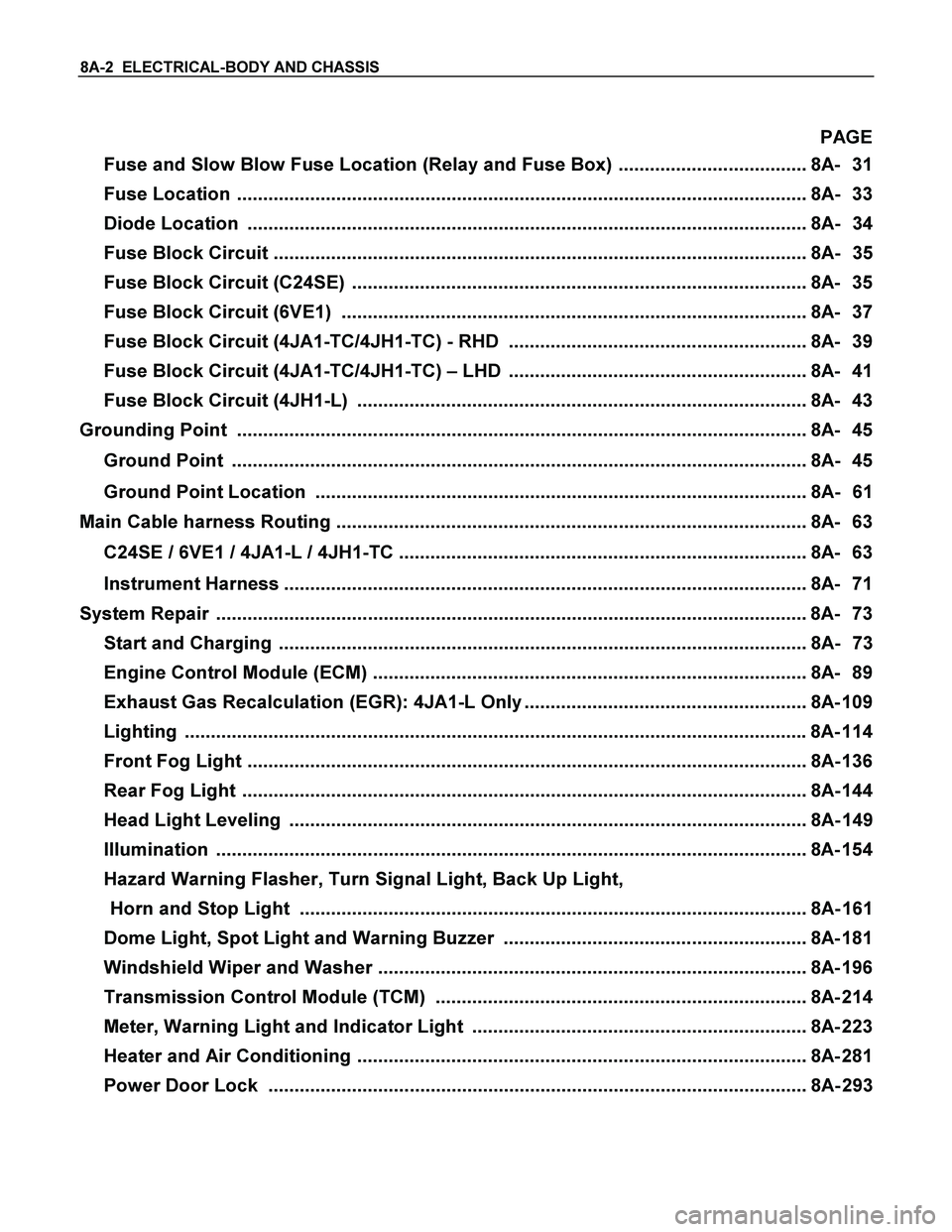
8A-2 ELECTRICAL-BODY AND CHASSIS
PAGE
Fuse and Slow Blow Fuse Location (Relay and Fuse Box) .................................... 8A- 31
Fuse Location ............................................................................................................. 8A- 33
Diode Location ........................................................................................................... 8A- 34
Fuse Block Circuit ...................................................................................................... 8A- 35
Fuse Block Circuit (C24SE) ....................................................................................... 8A- 35
Fuse Block Circuit (6VE1) ......................................................................................... 8A- 37
Fuse Block Circuit (4JA1-TC/4JH1-TC) - RHD ......................................................... 8A- 39
Fuse Block Circuit (4JA1-TC/4JH1-TC) – LHD ......................................................... 8A- 41
Fuse Block Circuit (4JH1-L) ...................................................................................... 8A- 43
Grounding Point ............................................................................................................. 8A- 45
Ground Point .............................................................................................................. 8A- 45
Ground Point Location .............................................................................................. 8A- 61
Main Cable harness Routing .......................................................................................... 8A- 63
C24SE / 6VE1 / 4JA1-L / 4JH1-TC .............................................................................. 8A- 63
Instrument Harness .................................................................................................... 8A- 71
System Repair .................................................................................................................8A- 73
Start and Charging ..................................................................................................... 8A- 73
Engine Control Module (ECM) ................................................................................... 8A- 89
Exhaust Gas Recalculation (EGR): 4JA1-L Only ...................................................... 8A- 109
Lighting ....................................................................................................................... 8A- 114
Front Fog Light ........................................................................................................... 8A- 136
Rear Fog Light ............................................................................................................ 8A- 144
Head Light Leveling ................................................................................................... 8A- 149
Illumination ................................................................................................................. 8A- 154
Hazard Warning Flasher, Turn Signal Light, Back Up Light,
Horn and Stop Light ................................................................................................. 8A- 161
Dome Light, Spot Light and Warning Buzzer .......................................................... 8A- 181
Windshield Wiper and Washer .................................................................................. 8A- 196
Transmission Control Module (TCM) ....................................................................... 8A- 214
Meter, Warning Light and Indicator Light ................................................................ 8A- 223
Heater and Air Conditioning ...................................................................................... 8A- 281
Power Door Lock ....................................................................................................... 8A- 293
Page 686 of 4264
8A-28 ELECTRICAL-BODY AND CHASSIS
RELAY LOCATION (RELAY AND FUSE BOX)
RELAY & FUSE BOX
RHD
NO. RELAY (C24SE) RELAY (6VE1) RELAY
(4JA1-TC/4JH1-TC)RELAY (4JA1-L)
X-1 RELAY; TAIL LIGHT
� � �
X-2 RELAY; FUEL PUMP
� RELAY; FRT FOG RELAY; FRT FOG
LIGHT
X-3 RELAY; HORN
� � �
X-4 RELAY; DIMMER
� � �
X-5 RELAY; FOG LIGHT
� RELAY; GLOW RELAY; GLOW
X-6 RELAY; STARTER
� RELAY; COND, FAN RELAY; CSD
X-7 RELAY; COND, FAN
� RELAY; RR FOG
�
X-8
� � RELAY; STARTER RELAY; STARTER
X-9 RELAY; HAZARD-RH
� � �
X-10 RELAY; HAZARD-LH
� � �
X-11 RELAY; HEATER
� � �
X-12 RELAY; HEAD
LIGHT � � �
X-13
� RELAY; ECM MAIN
� RELAY; COND, FAN
X-14 RELAY; A/C COMP
� � �
X-15 RELAY; THERMO
� � �