Page 1383 of 4264
4JA1/4JH1 ENGINE DRIVEABILITY AND EMISSIONS 6E–11
4JH1-TC
312
6
45
4
(1) Mass Air Flow (MAF) & Intake Air Temperature
(IAT) Sensor Assembly
(2) Throttle Cable
(3) Air Cleaner Case(4) Battery
(5) Relay & Fuse Box
(6) EGR Cooler (Euro3) / EGR Pipe (Ex cept Euro3)
Page 1384 of 4264
6E–12 4JA1/4JH1 ENGINE DRIVEABILITY AND EMISSIONS
324
1
(1) Throttle Position Sensor (TPS)
(2) Pump Control Unit (PSG)(3) Injection Pump Assembly
(4) Fuel Filter (Ex cept Euro 3)
213
(1) Mass Air Flow (MAF) & Intake Air Temperature
(IAT) Sensor Assembly
(2) EGR EVRV(3) Air Cleaner Case
Page 1385 of 4264
4JA1/4JH1 ENGINE DRIVEABILITY AND EMISSIONS 6E–13
(1) Engine Control Module (ECM)
(1) Engine Coolant Temperature (ECT) Sensor
(2) Thermo Unit for Water Temperature Gauge
(1) Vehicle Speed Sensor (VSS)
21
(1) EGR EVRV
(2) To Vacuum Pump
(3) To EGR Valve
(1) Crankshaft Position (CKP) Sensor
(2) Clutch Housing
321
12
Page 1413 of 4264
4JA1/4JH1 ENGINE DRIVEABILITY AND EMISSIONS 6E–41
No. Connector face No. Connector face
C-118
A/C Resister & Neutral switchE-23
Gray Idle SW
C-123 E-41
Black Coolant temp sensor
C-124 E-44
Gray Vehicle speed sensor
E-3
Black Magnetic clutch AC COMPE-49
Gray Glow plug
E-6 E-51
Black Inhibiter switch
E-9 H-4
White Engine room ~ Mission
E-10
Silver Engine groundH-6
White Engine room ~ INST
E-11
Natural
green Neutral switchH-7
White Engine room ~ INST
E-12
Natural
green Neutral switchH-18
White Engine room ~ INST
E-22
Brown TPS 1 mainH-22
White Engine ~ Engine room C
Page 1427 of 4264

4JA1/4JH1 ENGINE DRIVEABILITY AND EMISSIONS 6E–55
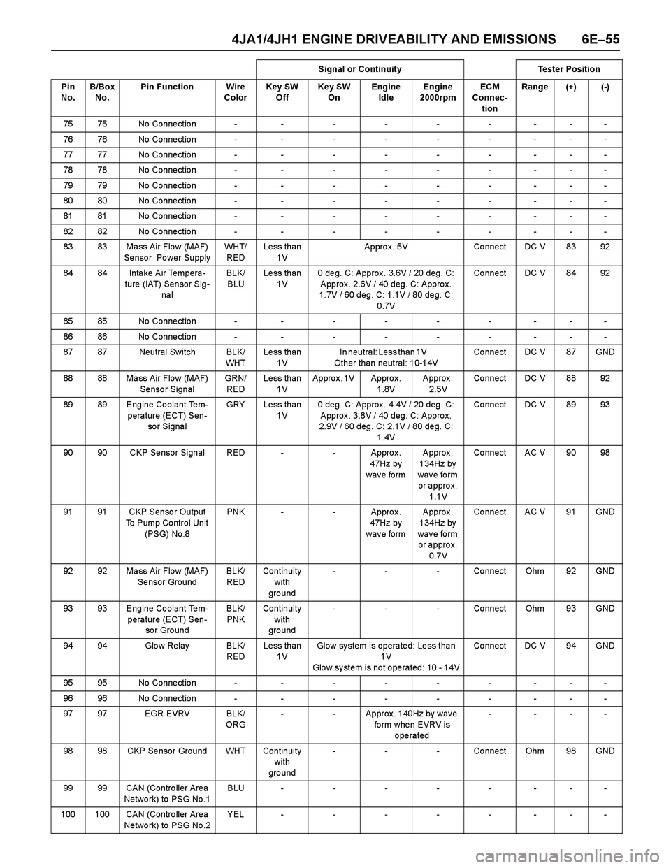
75 75 No Conne ctio n - - - - - - - - -
76 76 No Conne ctio n - - - - - - - - -
77 77 No Conne ctio n - - - - - - - - -
78 78 No Conne ctio n - - - - - - - - -
79 79 No Conne ctio n - - - - - - - - -
80 80 No Conne ctio n - - - - - - - - -
81 81 No Conne ctio n - - - - - - - - -
82 82 No Conne ctio n - - - - - - - - -
83 83 Ma ss Air Flo w (MAF)
Se nso r Po wer SupplyWH T/
REDLess than
1VAppro x . 5V Co nnect DC V 83 92
84 84 Intake Air Tempera-
ture (IAT) Sensor Sig-
na lBLK/
BLULess than
1V0 deg. C: Approx. 3.6V / 20 deg. C:
Approx. 2.6V / 40 deg. C: Approx.
1.7V / 60 deg. C: 1.1V / 80 deg. C:
0.7VCo nnect DC V 84 92
85 85 No Conne ctio n - - - - - - - - -
86 86 No Conne ctio n - - - - - - - - -
87 87 Neutral Switch BLK/
WH TLess than
1VIn neutral: Less than 1V
Other than neutral: 10-14VCo nnect DC V 87 GND
88 88 Ma ss Air Flo w (MAF)
Se nso r SignalGRN/
REDLess than
1VAppro x . 1V Appro x .
1.8VApprox.
2.5VCo nnect DC V 88 92
89 89 Engine Coolant Tem-
perature (ECT) Sen-
so r S ig na lGRY Less than
1V0 deg. C: Approx. 4.4V / 20 deg. C:
Approx. 3.8V / 40 deg. C: Approx.
2.9V / 60 deg. C: 2.1V / 80 deg. C:
1.4VCo nnect DC V 89 93
90 90 CKP Se nso r Signal RED - - Appro x .
47Hz by
w a v e fo rm Approx.
134Hz by
wave form
or approx.
1.1VCo nnect AC V 90 98
91 91 CKP Senso r Output
To Pump Co ntrol Unit
(PSG) No.8PNK - - Appro x .
47Hz by
w a v e fo rm Approx.
134Hz by
wave form
or approx.
0.7VCo nnect AC V 91 GND
92 92 Ma ss Air Flo w (MAF)
Se nsor GroundBLK/
REDContinuity
with
gro und- - - Connect Ohm 92 GND
93 93 Engine Coolant Tem-
perature (ECT) Sen-
so r Gro undBLK/
PNKContinuity
with
gro und- - - Connect Ohm 93 GND
94 94 Glo w Relay BLK/
REDLess than
1VGlow system is operated: Less than
1 V
Glow system is not operated: 10 - 14VCo nnect DC V 94 GND
95 95 No Conne ctio n - - - - - - - - -
96 96 No Conne ctio n - - - - - - - - -
97 97 EGR EVRV BLK/
ORG- - Approx. 140Hz by wave
fo rm whe n EVRV is
operated----
98 98 CKP Se nsor Ground WHT Continuity
with
gro und- - - Connect Ohm 98 GND
99 99 CAN (Contro ller Are a
Ne two rk) to PSG No .1BLU--------
100 100 CAN (Contro ller Are a
Ne two rk) to PSG No .2YEL--------Signal or Continuity Tester Position
Pin
No. B/Box
No.Pin Function Wire
ColorKey SW
OffKey SW
OnEngine
IdleEngine
2000rpmECM
Connec-
tionRange (+) (-)
Page 1429 of 4264

4JA1/4JH1 ENGINE DRIVEABILITY AND EMISSIONS 6E–57
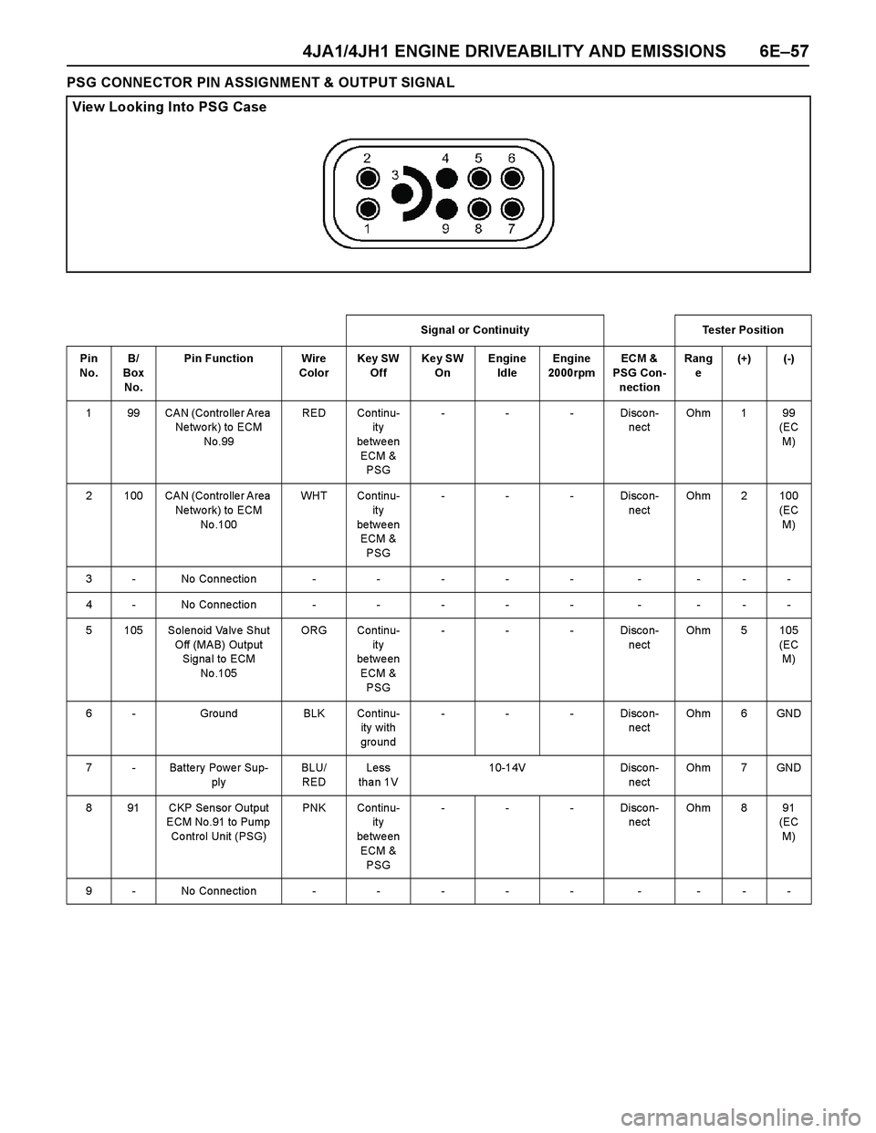
PSG CONNECTOR PIN ASSIGNMENT & OUTPUT SIGNAL
View Looking Into PSG Case
Signal or Continuity Tester Position
Pin
No. B/
Box
No.Pin Function Wire
ColorKey SW
OffKey SW
OnEngine
IdleEngine
2000rpmECM &
PSG Con-
nectionRang
e(+) (-)
1 99 CAN (Contro lle r Area
Ne two rk) to ECM
No.99RED Continu-
ity
between
ECM &
PSG- - - Disco n-
nectOhm 1 99
(EC
M)
2 100 CAN (Contro lle r Area
Ne two rk) to ECM
No .100WHT Continu-
ity
between
ECM &
PSG- - - Disco n-
nectOhm 2 100
(EC
M)
3 - No Connection - - - - - - - - -
4 - No Connection - - - - - - - - -
5 105 Solenoid Valve Shut
Off (MAB) Output
Signa l to ECM
No .105ORG Continu-
ity
between
ECM &
PSG- - - Disco n-
nectOhm 5 105
(EC
M)
6 - Ground BLK Continu-
ity with
gro und- - - Disco n-
nectOhm 6 GND
7 - Batte ry Powe r Sup-
plyBLU/
REDLess
tha n 1V10-14V Disco n-
nectOhm 7 GND
8 91 CKP Sensor Output
ECM No.91 to Pump
Co ntrol Unit (PSG)PNK Continu-
ity
between
ECM &
PSG- - - Disco n-
nectOhm 8 91
(EC
M)
9 - No Connection - - - - - - - - -
Page 1432 of 4264

6E–60 4JA1/4JH1 ENGINE DRIVEABILITY AND EMISSIONS
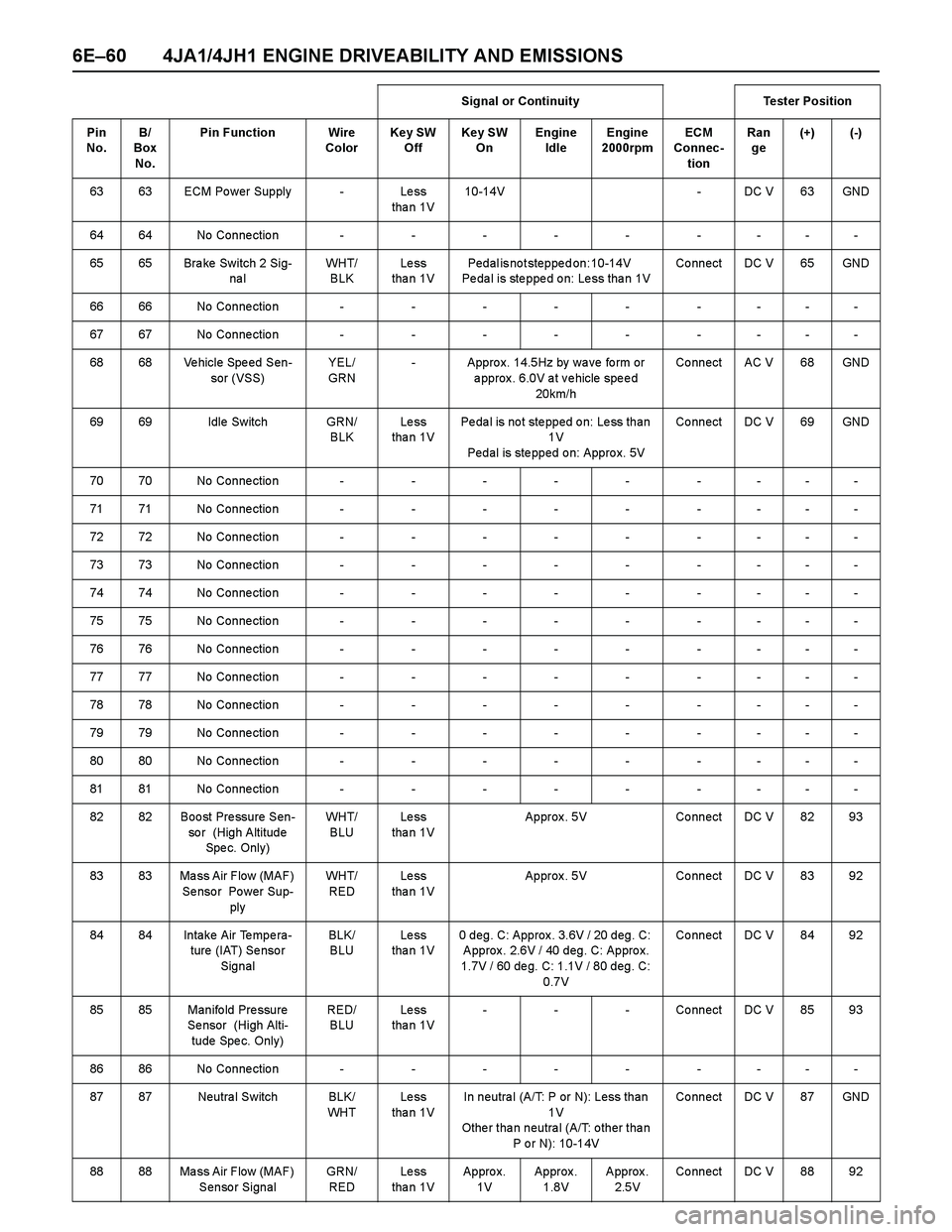
63 63 ECM Po wer Supply - Le ss
tha n 1V10-14V - DC V 63 GND
6464No Connection---------
65 65 Bra ke Switch 2 Sig-
na lWH T/
BLKLe ss
tha n 1VPedal is not stepped on: 10-14V
Pe da l is ste ppe d o n: Le ss tha n 1VCo nnect DC V 65 GND
6666No Connection---------
6767No Connection---------
68 68 Ve hicle Spe ed Sen-
sor (VSS)YEL/
GRN- Appro x. 14.5Hz by wa ve fo rm or
approx. 6.0V at vehicle speed
20km/hCo nnect AC V 68 GND
69 69 Idle Switch GRN/
BLKLe ss
tha n 1VPedal is not stepped on: Less than
1V
Pedal is stepped on: Approx. 5VCo nnect DC V 69 GND
7070No Connection---------
7171No Connection---------
7272No Connection---------
7373No Connection---------
7474No Connection---------
7575No Connection---------
7676No Connection---------
7777No Connection---------
7878No Connection---------
7979No Connection---------
8080No Connection---------
8181No Connection---------
82 82 Boo st Pre ssure Sen-
so r (High Altitude
Spe c. Onl y )WH T/
BLULe ss
tha n 1VApprox. 5V Connect DC V 82 93
83 83 Ma ss Air Flow (MAF)
Se nso r Po wer Sup-
plyWH T/
REDLe ss
tha n 1VApprox. 5V Connect DC V 83 92
84 84 Intake Air Tempera-
ture (IAT) Se nso r
SignalBLK/
BLULe ss
tha n 1V0 deg. C: Approx. 3.6V / 20 deg. C:
Approx. 2.6V / 40 deg. C: Approx.
1.7V / 60 deg. C: 1.1V / 80 deg. C:
0.7VCo nnect DC V 84 92
85 85 Manifo ld Pre ssure
Se nsor (High Alti-
tude Spe c. Only)RED/
BLULe ss
tha n 1V- - - Co nnect DC V 85 93
8686No Connection---------
87 87 Neutra l Switch BLK/
WH TLe ss
tha n 1VIn neutral (A/T: P or N): Less than
1 V
Othe r tha n neutra l (A/T: o ther tha n
P o r N): 10-14VCo nnect DC V 87 GND
88 88 Ma ss Air Flow (MAF)
Sensor SignalGRN/
REDLe ss
tha n 1VAppro x.
1V Approx .
1.8VApprox.
2.5VCo nnect DC V 88 92 Signal or Continuity Tester Position
Pin
No. B/
Box
No.Pin Function Wire
ColorKey SW
OffKey SW
OnEngine
IdleEngine
2000rpmECM
Connec-
tionRan
ge(+) (-)
Page 1433 of 4264

4JA1/4JH1 ENGINE DRIVEABILITY AND EMISSIONS 6E–61
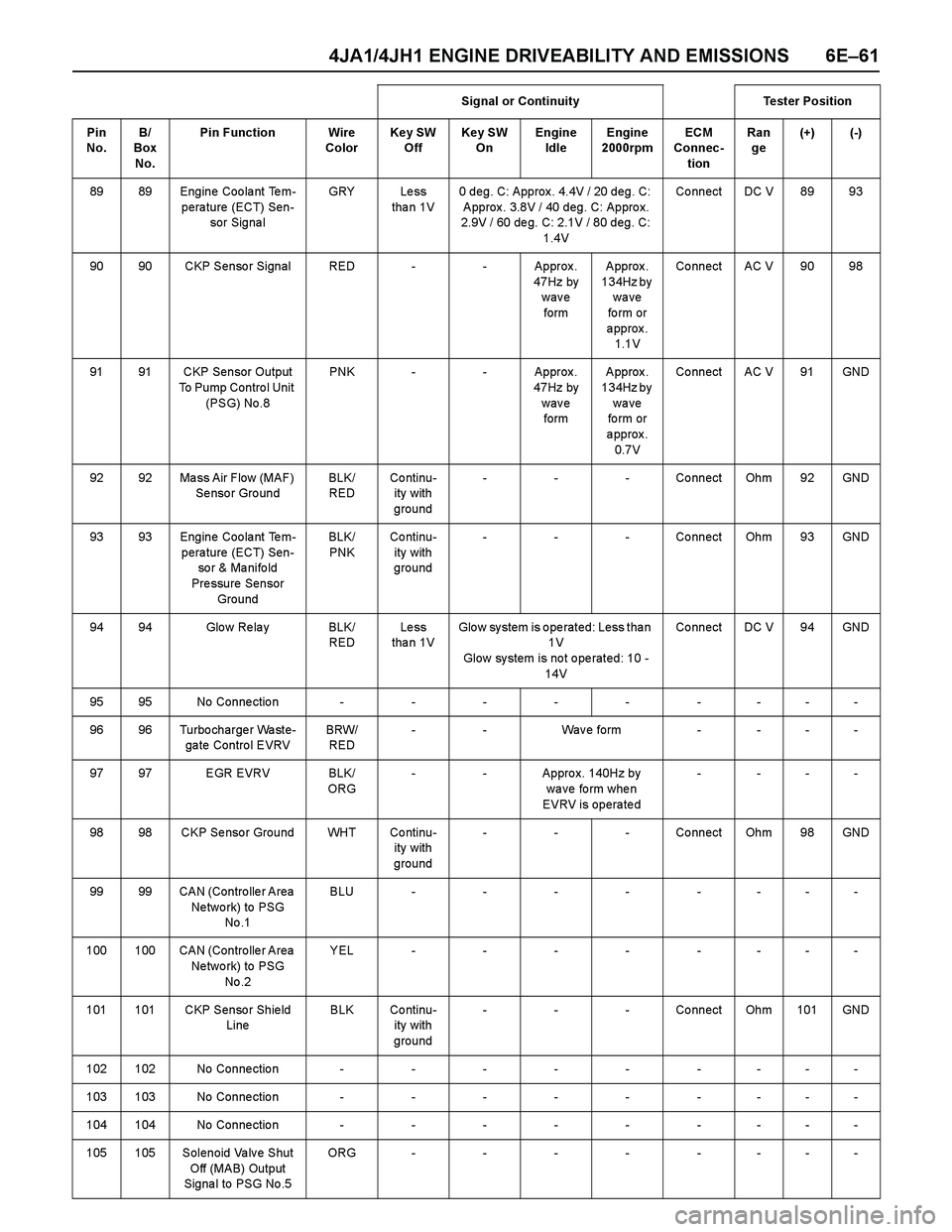
89 89 Engine Coolant Tem-
perature (ECT) Sen-
sor Signa lGRY Le ss
tha n 1V0 deg. C: Approx. 4.4V / 20 deg. C:
Approx. 3.8V / 40 deg. C: Approx.
2.9V / 60 deg. C: 2.1V / 80 deg. C:
1.4VCo nnect DC V 89 93
90 90 CKP Senso r Signal RED - - Approx .
47Hz by
wave
form Approx.
134Hz by
wave
fo rm or
approx.
1.1VCo nnect AC V 90 98
91 91 CKP Sensor Output
To Pump Contro l Unit
(PSG) No.8PNK - - Approx .
47Hz by
wave
form Approx.
134Hz by
wave
fo rm or
approx.
0.7VCo nnect AC V 91 GND
92 92 Ma ss Air Flow (MAF)
Se nso r Gro undBLK/
REDCo ntinu-
ity with
ground- - - Connect Ohm 92 GND
93 93 Engine Coolant Tem-
perature (ECT) Sen-
so r & Ma nifo ld
Pressure Sensor
GroundBLK/
PNKCo ntinu-
ity with
ground- - - Connect Ohm 93 GND
94 94 Glo w Re la y BLK/
REDLe ss
tha n 1VGlow system is operated: Less than
1 V
Glow system is not operated: 10 -
14VCo nnect DC V 94 GND
9595No Connection---------
96 96 Turbo charge r Wa ste-
ga te Contro l EVRVBRW/
RED- - Wav e form - - - -
97 97 EGR EVRV BLK/
ORG- - Appro x. 140Hz by
wa ve fo rm whe n
EVRV is operated- ---
98 98 CKP Se nso r Ground WHT Co ntinu-
ity with
ground- - - Connect Ohm 98 GND
99 99 CAN (Contro lle r Area
Ne two rk) to PSG
No .1BLU--------
100 100 CAN (Contro lle r Area
Ne two rk) to PSG
No .2YEL--------
101 101 CKP Senso r Shie ld
LineBLK Co ntinu-
ity with
ground- - - Connect Ohm 101 GND
102102No Connection---------
103103No Connection---------
104104No Connection---------
105 105 Solenoid Valve Shut
Off (MAB) Output
Signa l to PSG No .5ORG --------Signal or Continuity Tester Position
Pin
No. B/
Box
No.Pin Function Wire
ColorKey SW
OffKey SW
OnEngine
IdleEngine
2000rpmECM
Connec-
tionRan
ge(+) (-)