2004 ISUZU TF SERIES wiring
[x] Cancel search: wiringPage 1749 of 4264
4JA1/4JH1 ENGINE DRIVEABILITY AND EMISSIONS 6E–377
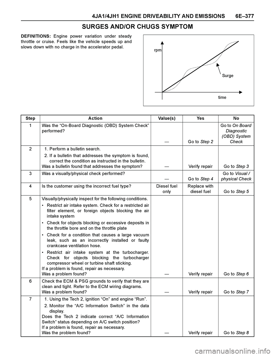
SURGES AND/OR CHUGS SYMPTOM
DEFINITIONS: Engine power variation under steady
throttle or cruise. Feels like the vehicle speeds up and
slows down with no charge in the accelerator pedal.
time rpm
Su rge
Step Action Value(s) Yes No
1Was the “On-Board Diagnostic (OBD) System Check”
performed?
—Go to Step 2Go to On Board
Diagnostic
(OBD) System
Check
2 1. Perform a bulletin search.
2. If a bulletin that addresses the symptom is found,
correct the condition as instructed in the bulletin.
Was a bulletin found that addresses the symptom?—Verify repair Go to Step 3
3 Was a visually/physical check performed?
—Go to Step 4Go to Visual /
physical Check
4 Is the customer using the incorrect fuel type? Diesel fuel
onlyReplace with
diesel fuel Go to Step 5
5 Visually/physically inspect for the following conditions.
Restrict air intake system. Check for a restricted air
filter element, or foreign objects blocking the air
intake system
Check for objects blocking or ex cessive deposits in
the throttle bore and on the throttle plate
Check for a condition that causes a large vacuum
leak, such as an incorrectly installed or faulty
crankcase ventilation hose.
Restrict air intake system at the turbocharger.
Check for objects blocking the turbocharger
compressor wheel or turbine shaft sticking.
If a problem is found, repair as necessary.
Was a problem found?—Verify repair Go to Step 6
6 Check the ECM & PSG grounds to verify that they are
clean and tight. Refer to the ECM wiring diagrams.
Was a problem found?—Verify repair Go to Step 7
7 1. Using the Tech 2, ignition “On” and engine “Run”.
2. Monitor the “A/C Information Switch” in the data
display.
Does the Tech 2 indicate correct “A/C Information
Switch” status depending on A/C switch position?
If a problem is found, repair as necessary.
Was the problem found?—Verify repair Go to Step 8
Page 1755 of 4264
4JA1/4JH1 ENGINE DRIVEABILITY AND EMISSIONS 6E–383
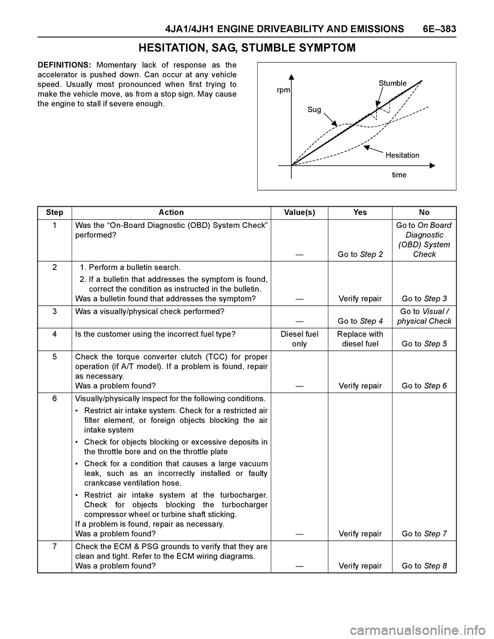
HESITATION, SAG, STUMBLE SYMPTOM
DEFINITIONS: Momentary lack of response as the
accelerator is pushed down. Can occur at any vehicle
speed. Usually most pronounced when first trying to
make the vehicle move, as from a stop sign. May cause
the engine to stall if severe enough.
time rpm
Sug
Hesitation Stumble
Step Action Value(s) Yes No
1Was the “On-Board Diagnostic (OBD) System Check”
performed?
—Go to Step 2Go to On Board
Diagnostic
(OBD) System
Check
2 1. Perform a bulletin search.
2. If a bulletin that addresses the symptom is found,
correct the condition as instructed in the bulletin.
Was a bulletin found that addresses the symptom?—Verify repair Go to Step 3
3 Was a visually/physical check performed?
—Go to Step 4Go to Visual /
physical Check
4 Is the customer using the incorrect fuel type? Diesel fuel
onlyReplace with
diesel fuel Go to Step 5
5 Check the torque converter clutch (TCC) for proper
operation (if A/T model). If a problem is found, repair
as necessary.
Was a problem found?—Verify repair Go to Step 6
6 Visually/physically inspect for the following conditions.
Restrict air intake system. Check for a restricted air
filter element, or foreign objects blocking the air
intake system
Check for objects blocking or ex cessive deposits in
the throttle bore and on the throttle plate
Check for a condition that causes a large vacuum
leak, such as an incorrectly installed or faulty
crankcase ventilation hose.
Restrict air intake system at the turbocharger.
Check for objects blocking the turbocharger
compressor wheel or turbine shaft sticking.
If a problem is found, repair as necessary.
Was a problem found?—Verify repair Go to Step 7
7 Check the ECM & PSG grounds to verify that they are
clean and tight. Refer to the ECM wiring diagrams.
Was a problem found?—Verify repair Go to Step 8
Page 1761 of 4264
4JA1/4JH1 ENGINE DRIVEABILITY AND EMISSIONS 6E–389
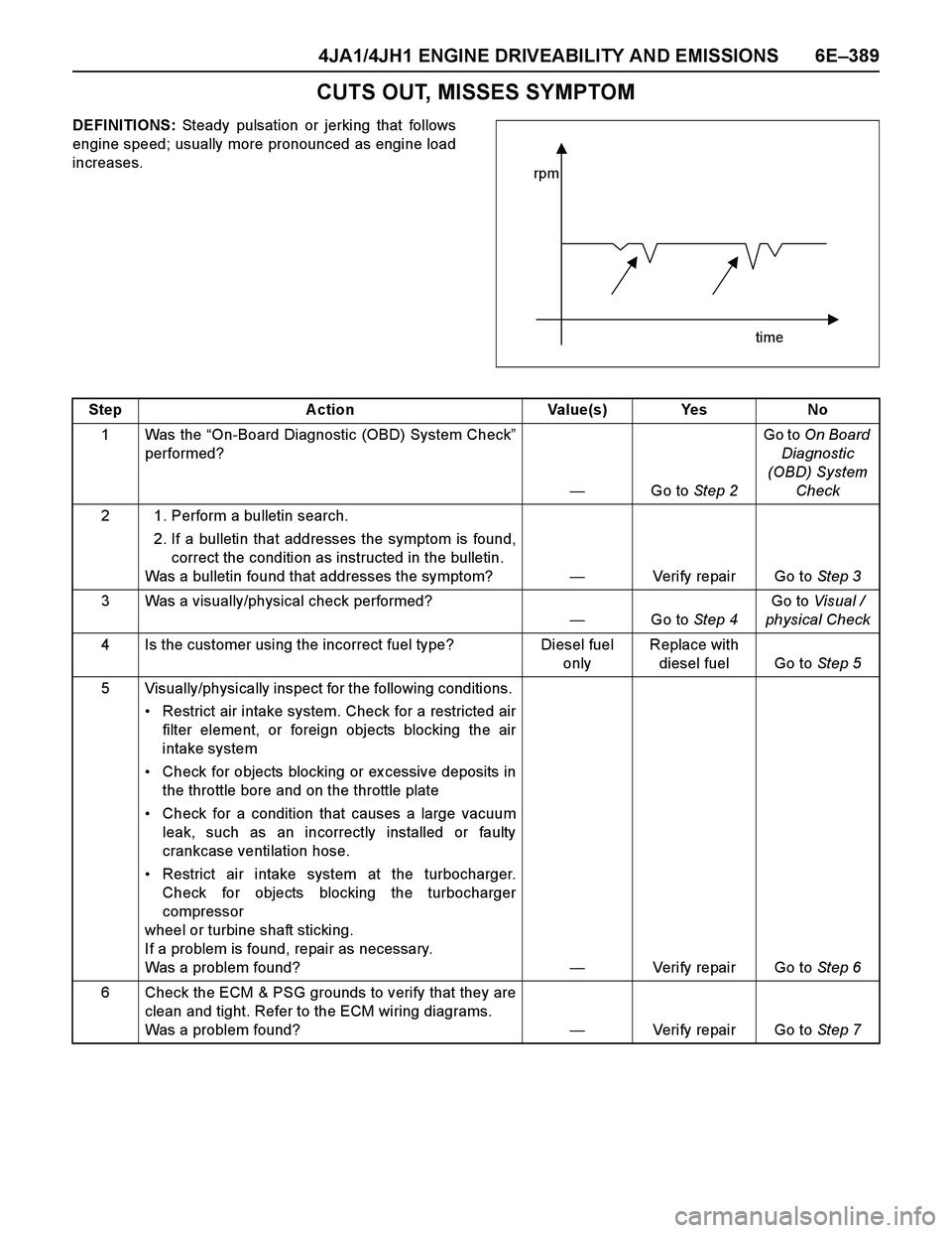
CUTS OUT, MISSES SYMPTOM
DEFINITIONS: Steady pulsation or jerking that follows
engine speed; usually more pronounced as engine load
increases.
time rpm
Step Action Value(s) Yes No
1Was the “On-Board Diagnostic (OBD) System Check”
performed?
—Go to Step 2Go to On Board
Diagnostic
(OBD) System
Check
2 1. Perform a bulletin search.
2. If a bulletin that addresses the symptom is found,
correct the condition as instructed in the bulletin.
Was a bulletin found that addresses the symptom?—Verify repair Go to Step 3
3 Was a visually/physical check performed?
—Go to Step 4Go to Visual /
physical Check
4 Is the customer using the incorrect fuel type? Diesel fuel
onlyReplace with
diesel fuel Go to Step 5
5 Visually/physically inspect for the following conditions.
Restrict air intake system. Check for a restricted air
filter element, or foreign objects blocking the air
intake system
Check for objects blocking or ex cessive deposits in
the throttle bore and on the throttle plate
Check for a condition that causes a large vacuum
leak, such as an incorrectly installed or faulty
crankcase ventilation hose.
Restrict air intake system at the turbocharger.
Check for objects blocking the turbocharger
compressor
wheel or turbine shaft sticking.
If a problem is found, repair as necessary.
Was a problem found?—Verify repair Go to Step 6
6 Check the ECM & PSG grounds to verify that they are
clean and tight. Refer to the ECM wiring diagrams.
Was a problem found?—Verify repair Go to Step 7
Page 1768 of 4264
6E–396 4JA1/4JH1 ENGINE DRIVEABILITY AND EMISSIONS
LACK OF POWER, SLUGGISH OR SPONGY SYMPTOM
DEFINITIONS: Engine delivers less than ex pected power. Attempting part-throttle acceleration results in little or no
increase in vehicle speed.
Step Action Value(s) Yes No
1Was the “On-Board Diagnostic (OBD) System Check”
performed?
—Go to Step 2Go to On Board
Diagnostic
(OBD) System
Check
2 1. Perform a bulletin search.
2. If a bulletin that addresses the symptom is found,
correct the condition as instructed in the bulletin.
Was a bulletin found that addresses the symptom?—Verify repair Go to Step 3
3 Was a visually/physical check performed?
—Go to Step 4Go to Visual /
physical Check
4 Is the customer using the incorrect fuel type? Diesel fuel
onlyReplace with
diesel fuel Go to Step 5
5 Visually/physically inspect for the following conditions.
Restrict air intake system. Check for a restricted air
filter element, or foreign objects blocking the air
intake system
Check for objects blocking or ex cessive deposits in
the throttle bore and on the throttle plate
Check for a condition that causes a large vacuum
leak, such as an incorrectly installed or faulty
crankcase ventilation hose.
Restrict air intake system at the turbocharger.
Check for objects blocking the turbocharger
compressor wheel or turbine shaft sticking.
If a problem is found, repair as necessary.
Was a problem found?—Verify repair Go to Step 6
6 Check the ECM & PSG grounds to verify that they are
clean and tight. Refer to the ECM wiring diagrams.
Was a problem found?—Verify repair Go to Step 7
7 1. Using the Tech 2, display the ECT sensor and IAT
sensor value.
2. Check the displayed value.
Does the Tech 2 indicate correct temperature
depending on engine condition?
If a problem is found, repair as necessary.
Was the problem found?—Verify repair Go to Step 8
8 1. Using the Tech 2, display the FT sensor value.
2. Check the displayed value.
Does the Tech 2 indicate correct temperature
depending on engine condition?
If a problem is found, repair as necessary.
Was the problem found?—Go to Step 29Go to Step 9
9 1. Using the Tech 2, ignition “On” and engine “Run”.
2. Monitor the “Mass Air Flow” in the data display.
Does the Tech 2 indicate correct “Mass Air Flow”
depending on accelerator pedal operation? —Go to Step 14Go to Step 10
Page 1779 of 4264
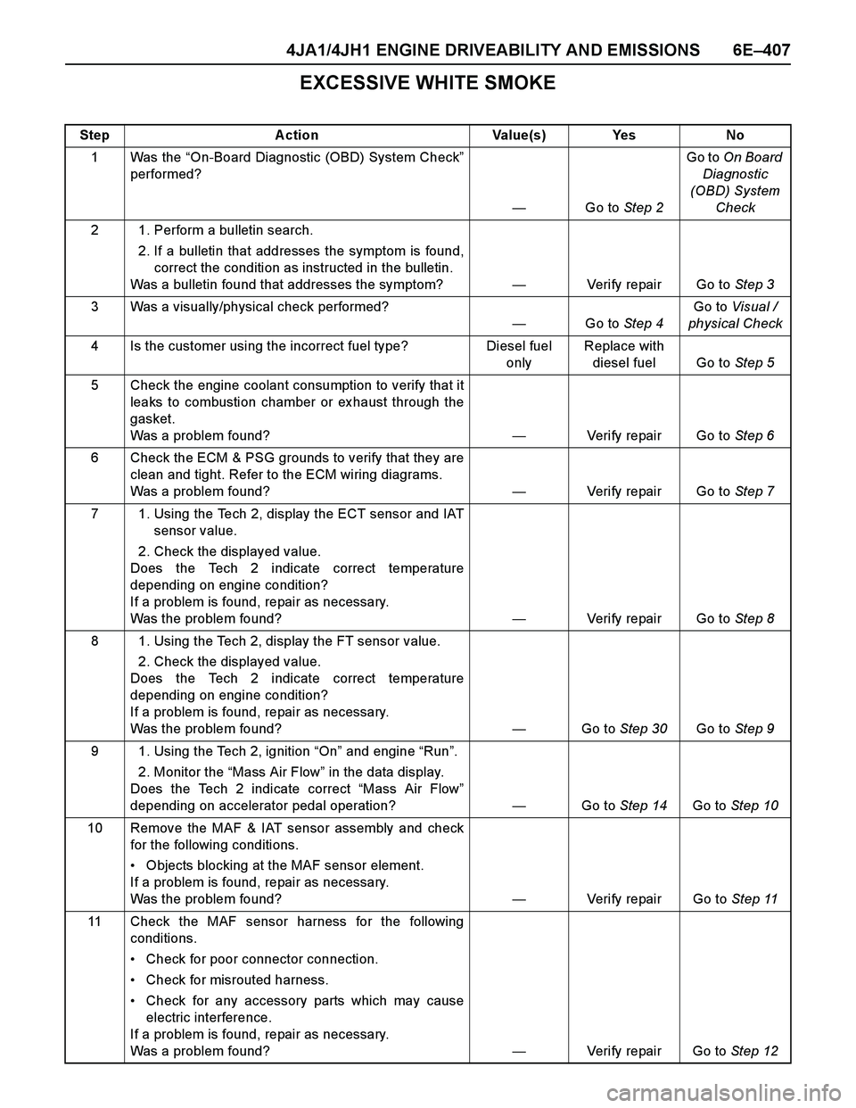
4JA1/4JH1 ENGINE DRIVEABILITY AND EMISSIONS 6E–407
EXCESSIVE WHITE SMOKE
Step Action Value(s) Yes No
1Was the “On-Board Diagnostic (OBD) System Check”
performed?
—Go to Step 2Go to On Board
Diagnostic
(OBD) System
Check
2 1. Perform a bulletin search.
2. If a bulletin that addresses the symptom is found,
correct the condition as instructed in the bulletin.
Was a bulletin found that addresses the symptom?—Verify repair Go to Step 3
3 Was a visually/physical check performed?
—Go to Step 4Go to Visual /
physical Check
4 Is the customer using the incorrect fuel type? Diesel fuel
onlyReplace with
diesel fuel Go to Step 5
5 Check the engine coolant consumption to verify that it
leaks to combustion chamber or ex haust through the
gasket.
Was a problem found?—Verify repair Go to Step 6
6 Check the ECM & PSG grounds to verify that they are
clean and tight. Refer to the ECM wiring diagrams.
Was a problem found?—Verify repair Go to Step 7
7 1. Using the Tech 2, display the ECT sensor and IAT
sensor value.
2. Check the displayed value.
Does the Tech 2 indicate correct temperature
depending on engine condition?
If a problem is found, repair as necessary.
Was the problem found?—Verify repair Go to Step 8
8 1. Using the Tech 2, display the FT sensor value.
2. Check the displayed value.
Does the Tech 2 indicate correct temperature
depending on engine condition?
If a problem is found, repair as necessary.
Was the problem found?—Go to Step 30Go to Step 9
9 1. Using the Tech 2, ignition “On” and engine “Run”.
2. Monitor the “Mass Air Flow” in the data display.
Does the Tech 2 indicate correct “Mass Air Flow”
depending on accelerator pedal operation? —Go to Step 14Go to Step 10
10 Remove the MAF & IAT sensor assembly and check
for the following conditions.
Objects blocking at the MAF sensor element.
If a problem is found, repair as necessary.
Was the problem found?—Verify repair Go to Step 11
11 Check the MAF sensor harness for the following
conditions.
Check for poor connector connection.
Check for misrouted harness.
Check for any accessory parts which may cause
electric interference.
If a problem is found, repair as necessary.
Was a problem found? —Verify repair Go to Step 12
Page 1785 of 4264
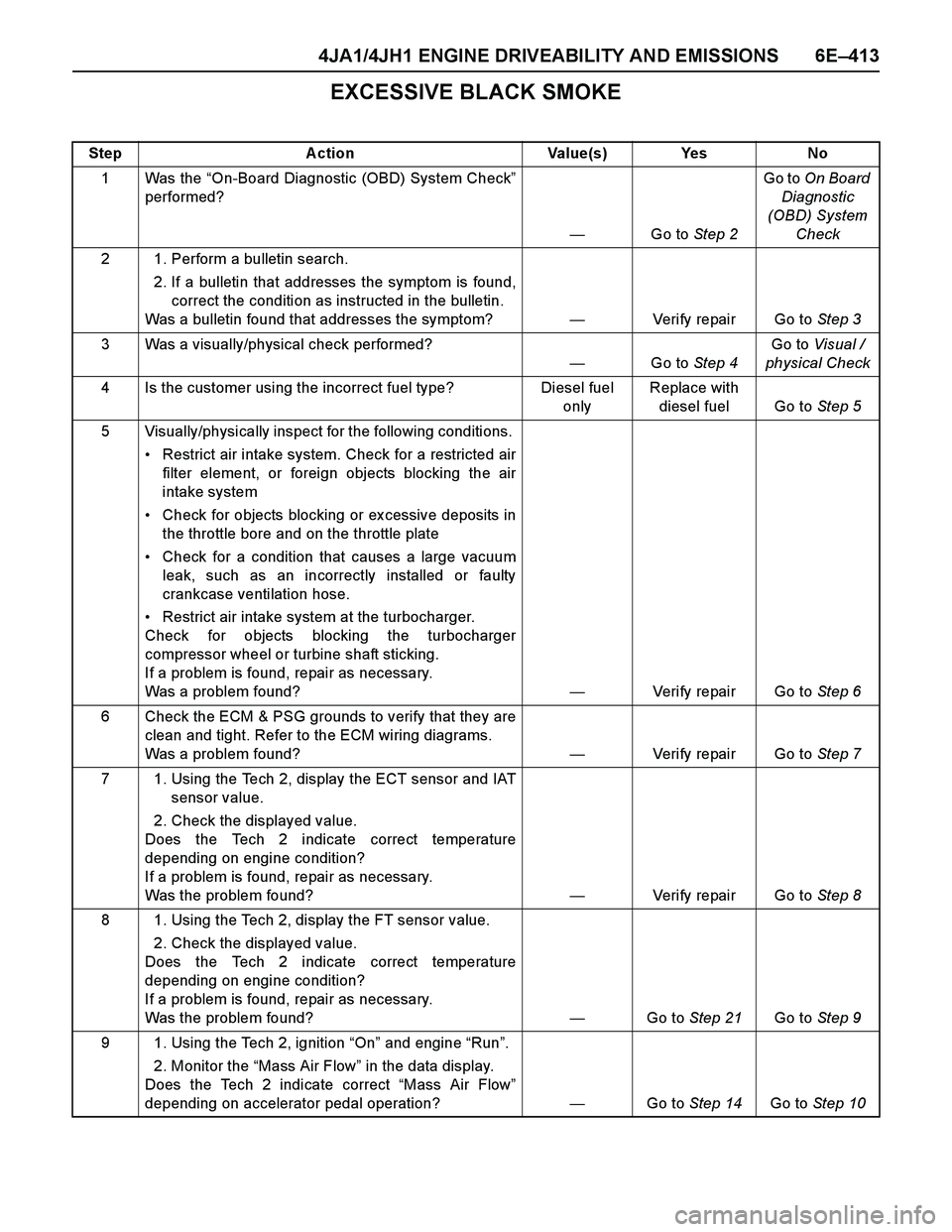
4JA1/4JH1 ENGINE DRIVEABILITY AND EMISSIONS 6E–413
EXCESSIVE BLACK SMOKE
Step Action Value(s) Yes No
1Was the “On-Board Diagnostic (OBD) System Check”
performed?
—Go to Step 2Go to On Board
Diagnostic
(OBD) System
Check
2 1. Perform a bulletin search.
2. If a bulletin that addresses the symptom is found,
correct the condition as instructed in the bulletin.
Was a bulletin found that addresses the symptom?—Verify repair Go to Step 3
3 Was a visually/physical check performed?
—Go to Step 4Go to Visual /
physical Check
4 Is the customer using the incorrect fuel type? Diesel fuel
onlyReplace with
diesel fuel Go to Step 5
5 Visually/physically inspect for the following conditions.
Restrict air intake system. Check for a restricted air
filter element, or foreign objects blocking the air
intake system
Check for objects blocking or ex cessive deposits in
the throttle bore and on the throttle plate
Check for a condition that causes a large vacuum
leak, such as an incorrectly installed or faulty
crankcase ventilation hose.
Restrict air intake system at the turbocharger.
Check for objects blocking the turbocharger
compressor wheel or turbine shaft sticking.
If a problem is found, repair as necessary.
Was a problem found?—Verify repair Go to Step 6
6 Check the ECM & PSG grounds to verify that they are
clean and tight. Refer to the ECM wiring diagrams.
Was a problem found?—Verify repair Go to Step 7
7 1. Using the Tech 2, display the ECT sensor and IAT
sensor value.
2. Check the displayed value.
Does the Tech 2 indicate correct temperature
depending on engine condition?
If a problem is found, repair as necessary.
Was the problem found?—Verify repair Go to Step 8
8 1. Using the Tech 2, display the FT sensor value.
2. Check the displayed value.
Does the Tech 2 indicate correct temperature
depending on engine condition?
If a problem is found, repair as necessary.
Was the problem found?—Go to Step 21Go to Step 9
9 1. Using the Tech 2, ignition “On” and engine “Run”.
2. Monitor the “Mass Air Flow” in the data display.
Does the Tech 2 indicate correct “Mass Air Flow”
depending on accelerator pedal operation? —Go to Step 14Go to Step 10
Page 1826 of 4264
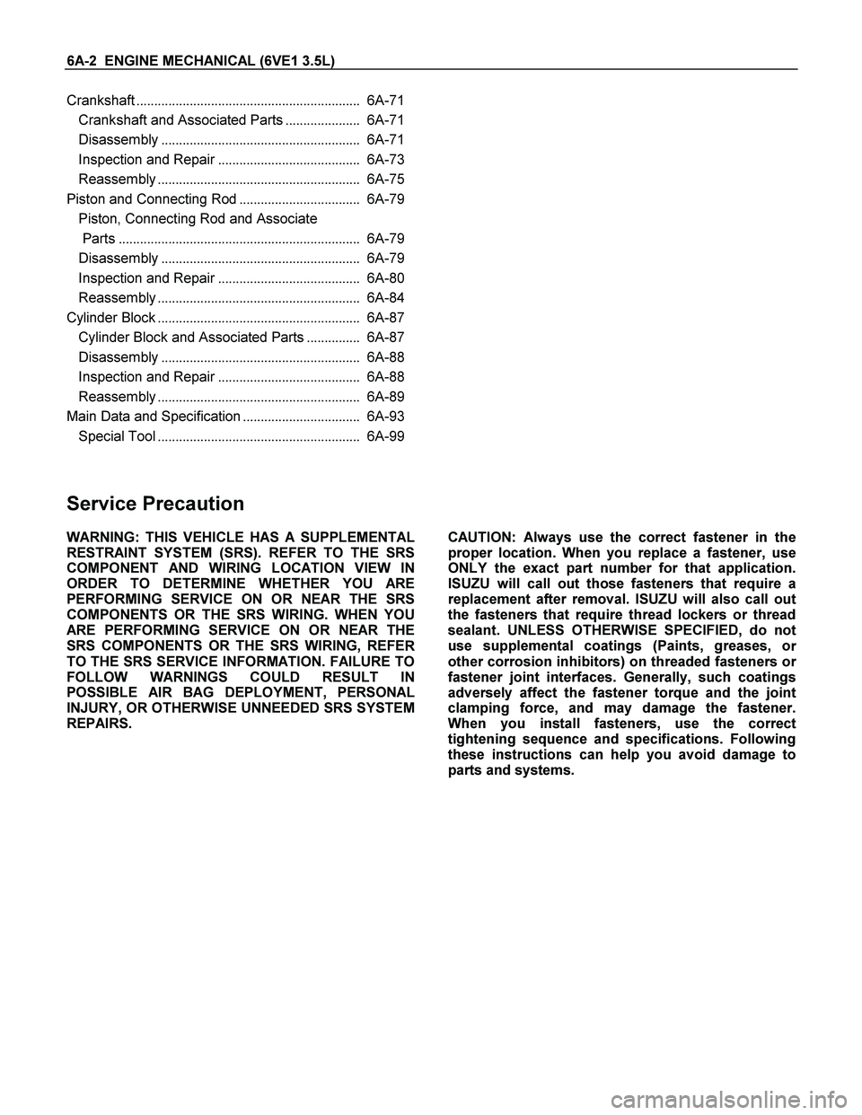
6A-2 ENGINE MECHANICAL (6VE1 3.5L)
Crankshaft............................................................... 6A-71
Crankshaft and Associated Parts..................... 6A-71
Disassembly........................................................ 6A-71
Inspection and Repair........................................ 6A-73
Reassembly......................................................... 6A-75
Piston and Connecting Rod.................................. 6A-79
Piston, Connecting Rod and Associate
Parts.................................................................... 6A-79
Disassembly........................................................ 6A-79
Inspection and Repair........................................ 6A-80
Reassembly......................................................... 6A-84
Cylinder Block......................................................... 6A-87
Cylinder Block and Associated Parts............... 6A-87
Disassembly........................................................ 6A-88
Inspection and Repair........................................ 6A-88
Reassembly......................................................... 6A-89
Main Data and Specification................................. 6A-93
Special Tool......................................................... 6A-99
Service Precaution
WARNING: THIS VEHICLE HAS A SUPPLEMENTAL
RESTRAINT SYSTEM (SRS). REFER TO THE SRS
COMPONENT AND WIRING LOCATION VIEW IN
ORDER TO DETERMINE WHETHER YOU ARE
PERFORMING SERVICE ON OR NEAR THE SRS
COMPONENTS OR THE SRS WIRING. WHEN YOU
ARE PERFORMING SERVICE ON OR NEAR THE
SRS COMPONENTS OR THE SRS WIRING, REFE
R
TO THE SRS SERVICE INFORMATION. FAILURE TO
FOLLOW WARNINGS COULD RESULT IN
POSSIBLE AIR BAG DEPLOYMENT, PERSONAL
INJURY, OR OTHERWISE UNNEEDED SRS SYSTEM
REPAIRS.
CAUTION: Always use the correct fastener in the
proper location. When you replace a fastener, use
ONLY the exact part number for that application.
ISUZU will call out those fasteners that require a
replacement after removal. ISUZU will also call out
the fasteners that require thread lockers or thread
sealant. UNLESS OTHERWISE SPECIFIED, do not
use supplemental coatings (Paints, greases, o
r
other corrosion inhibitors) on threaded fasteners o
r
fastener joint interfaces. Generally, such coatings
adversely affect the fastener torque and the joint
clamping force, and may damage the fastener.
When you install fasteners, use the correct
tightening sequence and specifications. Following
these instructions can help you avoid damage to
parts and systems.
Page 1925 of 4264
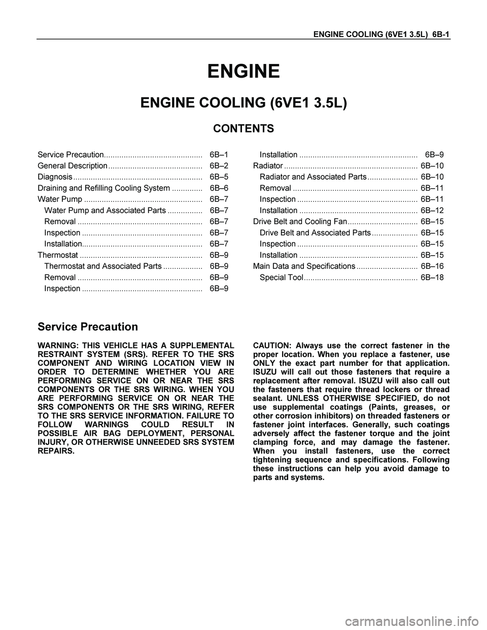
ENGINE COOLING (6VE1 3.5L) 6B-1
ENGINE
ENGINE COOLING (6VE1 3.5L)
CONTENTS
Service Precaution............................................. 6B–1
General Description ........................................... 6B–2
Diagnosis ........................................................... 6B–5
Draining and Refilling Cooling System .............. 6B–6
Water Pump ...................................................... 6B–7
Water Pump and Associated Parts ................ 6B–7
Removal ......................................................... 6B–7
Inspection ....................................................... 6B–7
Installation....................................................... 6B–7
Thermostat ........................................................ 6B–9
Thermostat and Associated Parts .................. 6B–9
Removal ......................................................... 6B–9
Inspection ....................................................... 6B–9
Installation ...................................................... 6B–9
Radiator ............................................................. 6B–10
Radiator and Associated Parts ....................... 6B–10
Removal ......................................................... 6B–11
Inspection ....................................................... 6B–11
Installation ...................................................... 6B–12
Drive Belt and Cooling Fan ................................ 6B–15
Drive Belt and Associated Parts ..................... 6B–15
Inspection ....................................................... 6B–15
Installation ...................................................... 6B–15
Main Data and Specifications ............................ 6B–16
Special Tool .................................................... 6B–18
Service Precaution
WARNING: THIS VEHICLE HAS A SUPPLEMENTAL
RESTRAINT SYSTEM (SRS). REFER TO THE SRS
COMPONENT AND WIRING LOCATION VIEW IN
ORDER TO DETERMINE WHETHER YOU ARE
PERFORMING SERVICE ON OR NEAR THE SRS
COMPONENTS OR THE SRS WIRING. WHEN YOU
ARE PERFORMING SERVICE ON OR NEAR THE
SRS COMPONENTS OR THE SRS WIRING, REFE
R
TO THE SRS SERVICE INFORMATION. FAILURE TO
FOLLOW WARNINGS COULD RESULT IN
POSSIBLE AIR BAG DEPLOYMENT, PERSONAL
INJURY, OR OTHERWISE UNNEEDED SRS SYSTEM
REPAIRS.
CAUTION: Always use the correct fastener in the
proper location. When you replace a fastener, use
ONLY the exact part number for that application.
ISUZU will call out those fasteners that require a
replacement after removal. ISUZU will also call out
the fasteners that require thread lockers or thread
sealant. UNLESS OTHERWISE SPECIFIED, do not
use supplemental coatings (Paints, greases, o
r
other corrosion inhibitors) on threaded fasteners or
fastener joint interfaces. Generally, such coatings
adversely affect the fastener torque and the joint
clamping force, and may damage the fastener.
When you install fasteners, use the correct
tightening sequence and specifications. Following
these instructions can help you avoid damage to
parts and systems.