Page 2232 of 4264
6E-236 3.5L ENGINE DRIVEABILITY AND EMISSIONS
Step Action Value (s) Yes No
6
Using the DVM and check the CKP sensor signal.
1. Ignition "On", engine "On".
2. Measure the CKP output voltage at the sensor and
ECM.
Does the tester indicate standard voltage?
Measurement Point Voltage (V) (AC Range)
At CKP sensor terminal 3 & GND
At ECM E60 connector A23 & GND
Approximately 1.9 V at 2000rpm
If a oscilloscope is available, monitor the CKP sensor
signal.
Does the oscilloscope indicate correct wave form?
Crankshaft Position (CKP) Sensor Reference Wave Form
0V
Measurement Terminal: A23(+) A25(-)
Measurement Scale: 2.0V/div 5ms/div
Measurement Condition: Approximately 2000rpm
Go to Step 17 Go to Step 7
7
Check for poor/faulty connection at the CKP sensor or
ECM connector. If a poor/faulty connection is found,
repair the faulty terminal.
Was the problem found?
E-60(A)��
��
��
E-59
�
�
�
- Verify repair Go to Step 8
Page 2233 of 4264
3.5L ENGINE DRIVEABILITY AND EMISSIONS 6E-237
Step Action Value (s) Yes No
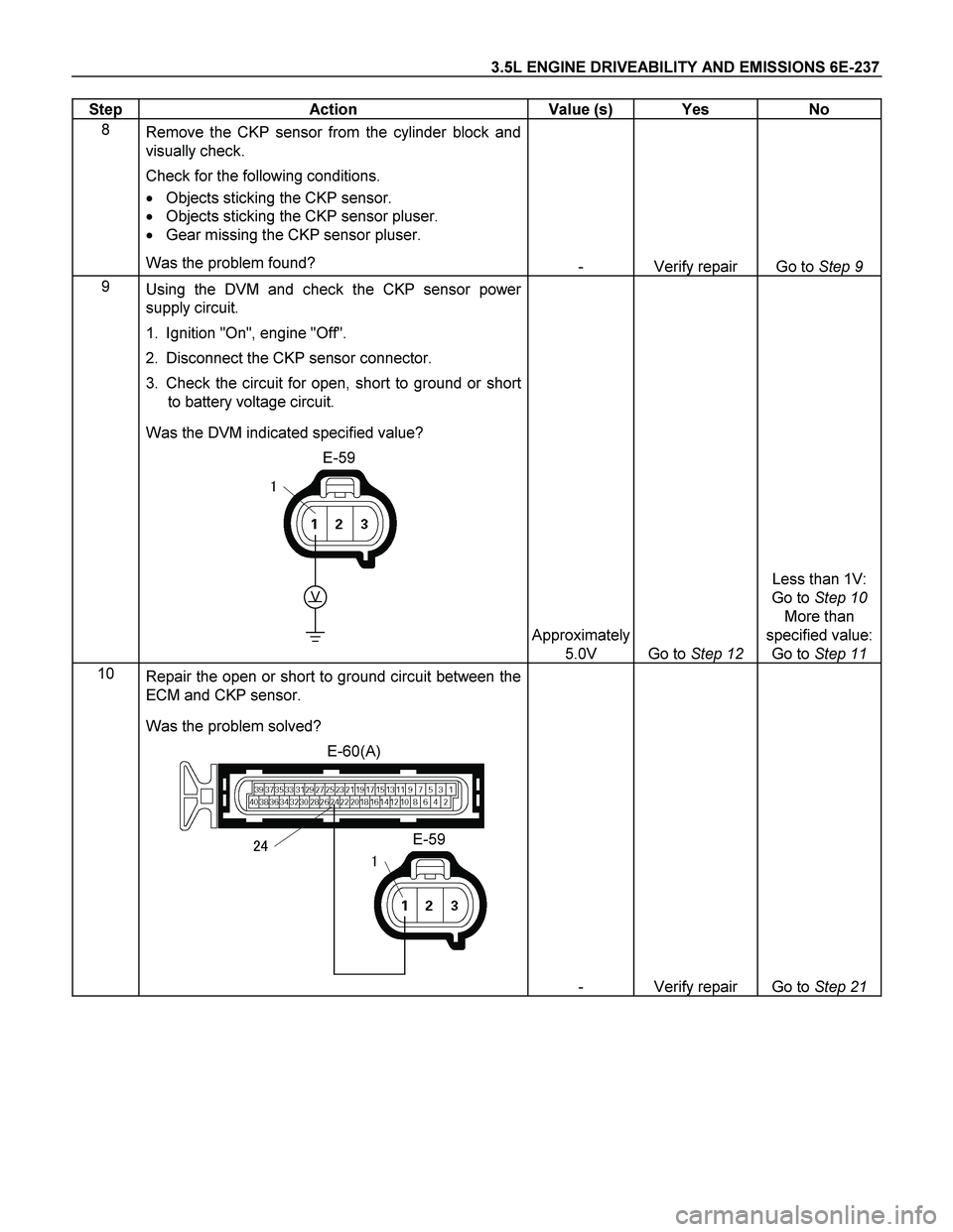
8
Remove the CKP sensor from the cylinder block and
visually check.
Check for the following conditions.
� Objects sticking the CKP sensor.
� Objects sticking the CKP sensor pluser.
� Gear missing the CKP sensor pluser.
Was the problem found?
- Verify repair Go to Step 9
9
Using the DVM and check the CKP sensor power
supply circuit.
1. Ignition "On", engine "Off".
2. Disconnect the CKP sensor connector.
3. Check the circuit for open, short to ground or short
to battery voltage circuit.
Was the DVM indicated specified value?
E-59
V
�
Approximately
5.0V
Go to Step 12
Less than 1V:
Go to Step 10
More than
specified value:
Go to Step 11
10
Repair the open or short to ground circuit between the
ECM and CKP sensor.
Was the problem solved?
E-60(A)
E-59���
- Verify repair Go to Step 21
Page 2234 of 4264
6E-238 3.5L ENGINE DRIVEABILITY AND EMISSIONS
Step Action Value (s) Yes No
11
Repair the short to battery voltage circuit between the
ECM and CKP sensor.
Was the problem solved?
E-60(A)
E-59���
- Verify repair Go to Step 21
12
Using the DVM and check the CKP sensor signal
circuit.
Breaker box is available:
1. Ignition "Off", engine "Off".
2. Install the breaker box as type A (ECM
disconnected).
Refer to 6E-95 page.
3. Disconnect the CKP sensor connector.
4. Check the circuit for open, short to sensor ground
or short to ground circuit.
Was the problem found?
E-59�
�
A23A25
�
Breaker Box
�
Page 2235 of 4264
3.5L ENGINE DRIVEABILITY AND EMISSIONS 6E-239
Step Action Value (s) Yes No
Breaker box is not available:
1. Ignition "Off", engine "Off".
2. Disconnect the CKP sensor connector and ECM
connector.
3. Check the circuit for open, short to sensor ground
or short to ground circuit.
Was the problem found?
E-60(A)
E-59
�
����
�
- Repair faulty
harness and
verify repair Go to Step 13
13
Using the DVM and check the CKP sensor signal
circuit.
1. Ignition "On", engine "Off".
2. Disconnect the CKP sensor connector.
3. Check the circuit for short to power supply circuit.
Was the DVM indicated specified value?
E-59
V
�
Less than 1V
Go to Step 14
Repair faulty
harness and
verify repair
Page 2236 of 4264
6E-240 3.5L ENGINE DRIVEABILITY AND EMISSIONS
Step Action Value (s) Yes No
14
Using the DVM and check the CKP sensor ground
circuit.
Breaker box is available:
1. Ignition "Off", engine "Off".
2. Install the breaker box as type A (ECM
disconnected).
Refer to 6E-95 page.
3. Disconnect CKP sensor connector.
4. Check the circuit for open circuit.
Was the problem found?
E-59�A25
Breaker Box
�
Breaker box is not available:
1. Ignition "Off", engine "Off".
2. Disconnect the CKP sensor connector and ECM
connector.
3. Check the circuit for open circuit.
Was the problem found?
E-60(A)
E-59
�
�
��
-
Repair faulty
harness and
verify repair
Go to Step 15
Page 2237 of 4264
 Yes No
15
Using the DVM and check the CKP ground circuit.
1. Ignition \"On\", engine \"Off\".
2. Disconnect the CKP sensor")
3.5L ENGINE DRIVEABILITY AND EMISSIONS 6E-241
Step Action Value (s) Yes No
15
Using the DVM and check the CKP ground circuit.
1. Ignition "On", engine "Off".
2. Disconnect the CKP sensor connector.
3. Check the circuit for short to power supply circuit.
Was the DVM indicated specified value?
E-59
V
�
Less than 1V
Go to Step 21
Repair faulty
harness and
verify repair
16
Check the CKP sensor shield wire for open or short
circuit.
Was the problem found?
- Verify repair Go to Step 17
17
Check for poor/faulty connection at the TPS, CMP
sensor or ECM connector. If a poor/faulty connection
is found, repair the faulty terminal.
Was the problem found?
E-61(B)
E-62E-68
��
��
�
��
�
��
��
- Verify repair Go to Step 18
18
Using the DVM and check the CMP sensor signal
circuit.
1. Ignition "Off", engine "Off".
2. Disconnect the CMP sensor connector and ECM
connector.
3. Check the circuit for short to sensor ground or short
to ground circuit.
Was the problem found?
E-62
��
��
-
Repair faulty
harness and
verify repair
Go to Step 19
Page 2238 of 4264
 Yes No
19
Using the DVM and check the TPS or CMP sensor
power supply circuit.
1. Ignition \"On\", engine \"Off\".
2. Disc")
6E-242 3.5L ENGINE DRIVEABILITY AND EMISSIONS
Step Action Value (s) Yes No
19
Using the DVM and check the TPS or CMP sensor
power supply circuit.
1. Ignition "On", engine "Off".
2. Disconnect the TPS or CMP sensor connector.
3. Check the circuit for open or short to ground circuit.
Was the DVM indicated specified value?
E-62
E-68
VV
�
�
Approximately
5.0V
Go to Step 23
Go to Step 20
20
Repair the short to ground circuit between the ECM
and TPS or CMP sensor.
Was the problem solved?
- Verify repair Go to Step 23
21
Substitute a known good CKP sensor and recheck.
Was the problem solved?
- Go to Step 21 Go to Step 23
22
Replace the CKP sensor.
Was the problem solved?
- Verify repair Go to Step 23
23
Is the ECM programmed with the latest software
release?
If not, download the latest software to the ECM using
the "SPS (Service Programming System)".
Was the problem solved?
- Verify repair Go to Step 24
24
Replace the ECM.
Is the action complete?
IMPORTANT: The replacement ECM must be
programmed. Refer to section of the Service
Programming System (SPS) in this manual. Following
ECM programming, the immobilizer system (if
equipped) must be linked to the ECM. Refer to section
11 “Immobilizer System-ECM replacement” for the
ECM/Immobilizer linking procedure.
- Verify repair -
Page 2239 of 4264
3.5L ENGINE DRIVEABILITY AND EMISSIONS 6E-243
DIAGNOSTIC TROUBLE CODE (DTC) P0341(FLASH CODE 41) CAMSHAFT
POSITION SENSOR CIRCUIT RANGE/PERFORMANCE
DIAGNOSTIC TROUBLE CODE (DTC) P0342 (FLASH CODE 41) CAMSHAFT
POSITION SENSOR CIRCUIT NO SIGNAL
RUW46EMF000101
Condition For Setting The DTC and Action Taken When The DTC Sets
Flash
Code Code Type DTC Name DTC Setting Condition Fail-Safe (Back Up)
P0341 B Camshaft Position
Sensor Circuit
Range/Performance 1. Engine speed below 2000rpm.
2. No crankshaft position sensor DTC P0336 or P0337.
3. Incorrect pulse is detected consecutively. 41
P0342 B Camshaft Position
Sensor Circuit No
Signal 1. No DTC relating to CKP sensor.
2. Engine speed is below 2000rpm.
3. No pulse is detected consecutively. Fuel cut is operated at high engine
speed.
 Yes No
6
Using the DVM and check the CKP sensor signal.
1. Ignition \"On\", engine \"On\".
2. Measure the CKP output vol")
 Yes No
11
Repair the short to battery voltage circuit between the
ECM and CKP sensor.
Was the problem solved?
E-60(A)
E-")
 Yes No
Breaker box is not available:
1. Ignition \"Off\", engine \"Off\".
2. Disconnect the CKP sensor connector and ECM")
 Yes No
14
Using the DVM and check the CKP sensor ground
circuit.
Breaker box is available:
1. Ignition \"Off\", engine")
 P0341(FLASH CODE 41) CAMSHAFT
POSITION SENSOR CIRCUIT RANGE/PERFORMANCE
DIAGNOSTIC TROUBLE CODE (DTC) P0342 (FLASH CODE")