Page 1215 of 4264

4JA1T(L)
4JA1")
ENGINE MECHANICAL 6A – 75
2. Measure the piston diameter.
Piston Measuring Point mm (in)
4JA1T(L)
4JA1TC 78 (3.07)
4JH1TC 70 (2.76)
Piston Grade (Service Part) mm (in)
AX 92.949 - 92.964
(3.6549 - 3.6600)
4JA1T(L)
4JA1TC
CX 92.965 - 92.980
(3.6600 - 3.6606)
AX 95.359 - 95.374
(3.7542 - 3.7548)
4JH1TC
CX 95.375 - 95.390
(3.7548 - 3.7555)
Cylinder Liner and Piston Clearance mm (in)
4JA1T(L)
4JA1TC 0.041-0.071 (0.0016-0.0027)
4JH1TC 0.047-0.065 (0.0019-0.0026)
NOTE:
Cylinder liner kit clearances are preset. However, the
cylinder liner installation procedure may result in
slight decreases in cylinder liner clearances. Always
measure the cylinder liner clearance after installation
to be sure that it is correct.
TAPPET AND PUSH ROD
Visually inspect the tappet contact surfaces for pitting,
cracking, and other abnormal conditions. The tappet must be
replaced if any of these conditions are present.
Refer to the illustration at the left.
1. Normal contact
2. Cracking
3. Pitting
4. Irregular contact Uneven contact
5. Irregular contact One-sided contact
NOTE:
The tappet surfaces are spherical. Do not attempt to
grind them with an oil stone or similar tool in an effort
to repair the tappet. If the tappet is damaged, it must
be replaced.
015LX021
014RY00028
Page 1276 of 4264
6A – 136 ENGINE MECHANICAL
RTW36ASH000601
Removal
1. Radiator Grille
� Refer to removal procedure in Sheet Metal section.
RTW36ASH000501
2. Front Bumper Fascia
� Remove the nine clips and four screws.
� Disconnect the fog light harness connectors.
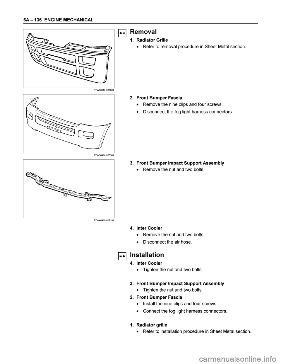
RTW46ASH002101
3. Front Bumper Impact Support Assembly
� Remove the nut and two bolts.
4. Inter Cooler
� Remove the nut and two bolts.
� Disconnect the air hose.
Installation
4. Inter Cooler
� Tighten the nut and two bolts.
3. Front Bumper Impact Support Assembly
� Tighten the nut and two bolts.
2. Front Bumper Fascia
� Install the nine clips and four screws.
� Connect the fog light harness connectors.
1. Radiator grille
� Refer to installation procedure in Sheet Metal section.
Page 1305 of 4264
FUEL SYSTEM 6C – 5
FUEL FILTER AND WATER SEPARATOR
As the inside of the injection pump is lubricated by the fuel which it is pumping, the fuel must be perfectly clean. The
fuel filter and the water separator remove water particles and other foreign material from the fuel before it reaches
the injection pump.
The water separator has an internal float. When the float reaches the specified level, a warning light comes on to
remind you to drain the water from the water separator.
A diaphragm type priming pump is installed at the top of the fuel filter. It is used during the air bleeding procedures.
(Except EURO III model)
RTW36CLF000701
Page 1307 of 4264
:
A Bosch Distributor Type Injection Pump is used. A single reciprocating/revolving plunger delivers the fuel uniformly
to th")
FUEL SYSTEM 6C – 7
INJECTION PUMP
RTW46CLF000201
4JA1T(L):
A Bosch Distributor Type Injection Pump is used. A single reciprocating/revolving plunger delivers the fuel uniformly
to the injection nozzles, regardless of the number of cylinders.
The governor, the injection timer, and the feed pump are all contained in the injection pump housing. The injection
pump is compact, light weight, and provides reliable high-speed operation.
The vacuum-type fast idle actuator increases the engine idling speed to provide the additional power required to
operate the air conditioner.
Fast idler diaphragm movement is caused by changes in the negative pressure created by the engine’s vacuum
pump.
The diaphragm motion is transferred to the injection pump control lever to increase or decrease the idling speed.
4JA1TC/4JH1TC:
The Bosch VP44 injection pump is electronically controlled. The pump controller combine to injection pump.
Signals from the pump controller are sent to the engine control module (ECM). In response to these signals, the
ECM selects the optimum fuel injection timing and volume for the existing driving conditions.
Page 1315 of 4264

FUEL SYSTEM 6C – 15
FUEL TUBE / QUICK – CONNECTOR FITTINGS
Precautions
�
Do not light a match or create a flame.
�
Keep flames away from your work area to preven
t
flammable materials from catching fire.
�
Disconnect battery ground cable to prevent electrical shorts.
�
Pre-treat piping system or associated parts from thermal
damage or from spattering when welding or simila
r
heat-generating work.
140R100032
Legend
(1)
O-ring
(2)
Port
(3)
Connector
(4)
Plastic Tube
Cautions During Work
Do not expose the assembly to battery electrolyte or do not
wipe the assembly with a cloth used to wipe off spilt battery
electrolyte.
Piping that has been splattered with battery electrolyte or
battery electrolyte soaked cloth that was wiped on the piping
cannot be used.
141R100002
Removal
1. Open the fuel cap to relieve the fuel pressure in the tank.
Use compressed air to remove any dirt on the fuel quick
connect fittings prior to disconnecting the fittings.
When disconnecting the fuel pipe, cover the area with a
cloth to prevent fuel from splashing as the fuel pipe ma
y
still have some pressure in it.
Page 1316 of 4264

6C – 16 FUEL SYSTEM
140R100037
2. For removal of the quick connector, hold the quick
connector in one hand, and pull out the connector with the
other hand while pressing the square relieve button of the
connector, as illustrated.
NOTE: Do not use tools of any kind. Only use bare hands
when disconnecting the connector. Use a lubricant (light oil)
and/or push and pull the connector until the pipe is
disconnected.
140R100028
Cover the connectors that was removed with a plastic bag,
to prevent dust or rain water from entering.
140R100036
Reuse of Quick–Connector
�
Replace the port and connector if scratch, dent or crack is
found.
� Remove any dirt build up on the port when installing the
connector. Replace the connector, if there is any forms o
f
rust, dent, scratch.
�
After cleaning the port, insert it straight into the connector
until it clicks. After it clicks, try pulling at 49N (5kgf) it out to
make sure that it is not drawn and is securely locked.
Assembling Advice
By applying engine oil or light oil to the pipe, port makes pipe
assembly easier. The pipe assembly should take place
immediately after applying oil (to prevent dust from sticking to
the pipe surface – which may decrease sealing ability).
Test/Inspection After Assembling
1. Reconnect the battery negative cable.
2. Start the engine and observe the engine idle speed. The
presence of dirt in the fuel system may affect the fuel
injection system.
3. Check for fuel leakage from the connector.
Page 1327 of 4264
FUEL SYSTEM 6C – 27
REASSEMBLY
080L200010
Reassembly Steps
1.
Nozzle holder body 9.
Spring seat
2.
Shim (First opening pressure
adjustment) 10.
Lift Piece
3.
First spring 11.
Spacer & pin
4.
Spring seat 12.
Nozzle & pin
5.
Collar 13.
Retaining nut
6.
Second spring 14.
Gasket
7.
Push rod 15.
Eye bolt
8.
Shim (Second opening pressure
adjustment)
Important Operations
The nozzle holder is adjusted as the components are
reassembled in the sequence above.
As adjustment of the two-spring nozzle holder is made in
hundredths of a millimeter, clean the parts thoroughly in
light oil to completely remove any dirt or foreign matter.
Page 1348 of 4264
6D – 10 ENGINE ELECTRICAL
RTW46DSH000101
Important Operations
1. Vacuum Pump
1. Loosen the vacuum pump fixing screws.
2. Support the vacuum pump O-ring.
3. Carefully remove the O-ring.
2. Cover
RTW46DSH000201
3. Through Bolt
1. Remove the M5 through bolt.
2. Separate the front and rear sides of the vacuum pump.
3. Insert the tips of 2 ordinary screwdrivers into the space
between the front cover and the stator core. Remove
the front cover and rotor together with the rear cover
and stator.
If removal is difficult, push the rear cover to the side and
lightly tap the end of the shaft with a plastic hammer to
loosen it.
� The front cover oil seal must be replaced with a new
one when the front cover is removed.
� Take care not to damage the stator core with the
screwdriver tips.
RTW46DSH000601
RTW46DSH002101
4. Pulley
1. Carefully clamp the rotor assembly in a vise.
2. Loosen the pulley nut.
3. Remove the pulley and the front cover from the rotor.