2004 ISUZU TF SERIES fuel
[x] Cancel search: fuelPage 1438 of 4264
6E–66 4JA1/4JH1 ENGINE DRIVEABILITY AND EMISSIONS
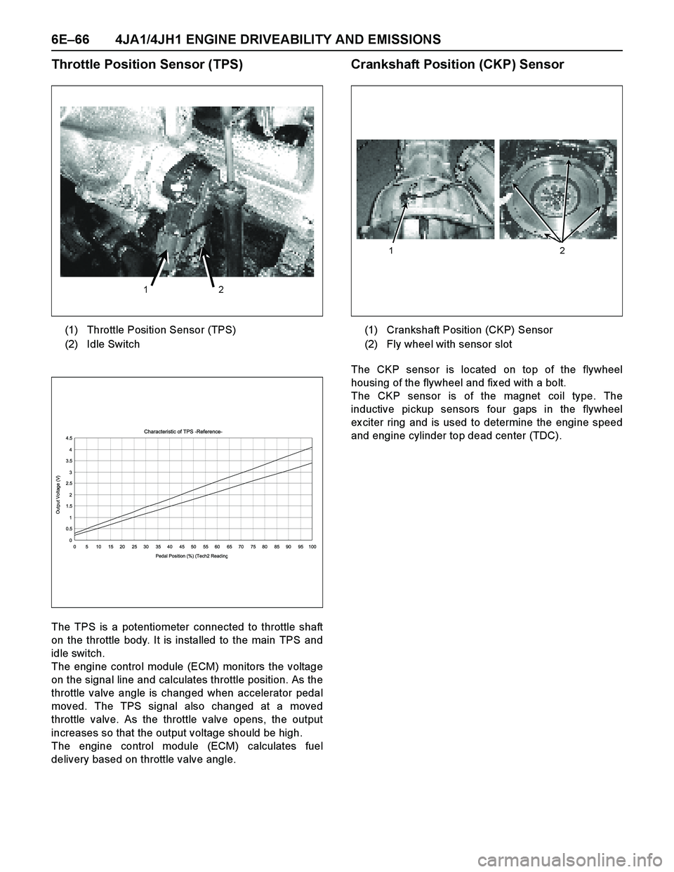
Throttle Position Sensor (TPS)
The TPS is a potentiometer connected to throttle shaft
on the throttle body. It is installed to the main TPS and
idle switch.
The engine control module (ECM) monitors the voltage
on the signal line and calculates throttle position. As the
throttle valve angle is changed when accelerator pedal
moved. The TPS signal also changed at a moved
throttle valve. As the throttle valve opens, the output
increases so that the output voltage should be high.
The engine control module (ECM) calculates fuel
delivery based on throttle valve angle.
Crankshaft Position (CKP) Sensor
The CKP sensor is located on top of the flywheel
housing of the flywheel and fix ed with a bolt.
The CKP sensor is of the magnet coil type. The
inductive pickup sensors four gaps in the flywheel
ex citer ring and is used to determine the engine speed
and engine cylinder top dead center (TDC). (1) Throttle Position Sensor (TPS)
(2) Idle Switch
1 2
Characteristic of TPS -Reference-
0 0.51 1.52 2.53 3.54 4.5
0 5 10 15 20 25 30 35 40 45 50 55 60 65 70 75 80 85 90 95 100
Pedal Position (%) (Tech2 Readin
g
Output Voltage (V)
(1) Crankshaft Position (CKP) Sensor
(2) Fly wheel with sensor slot
1 2
Page 1442 of 4264
6E–70 4JA1/4JH1 ENGINE DRIVEABILITY AND EMISSIONS
GENERAL DESCRIPTION FOR INJECTION
PUMP
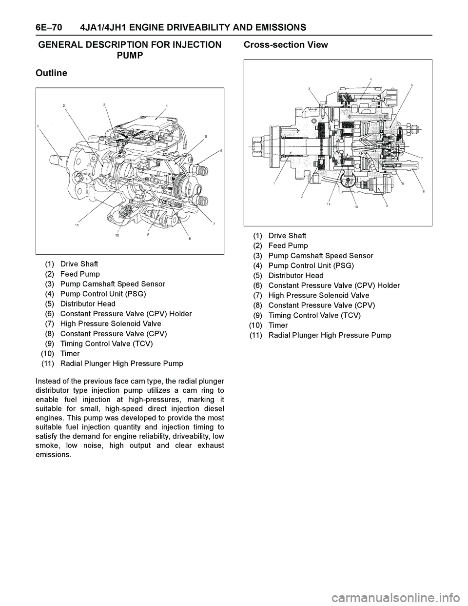
Outline
Instead of the previous face cam type, the radial plunger
distributor type injection pump utilizes a cam ring to
enable fuel injection at high-pressures, marking it
suitable for small, high-speed direct injection diesel
engines. This pump was developed to provide the most
suitable fuel injection quantity and injection timing to
satisfy the demand for engine reliability, driveability, low
smoke, low noise, high output and clear ex haust
emissions.
Cross-section View
(1) Drive Shaft
(2) Feed Pump
(3) Pump Camshaft Speed Sensor
(4) Pump Control Unit (PSG)
(5) Distributor Head
(6) Constant Pressure Valve (CPV) Holder
(7) High Pressure Solenoid Valve
(8) Constant Pressure Valve (CPV)
(9) Timing Control Valve (TCV)
(10) Timer
(11) Radial Plunger High Pressure Pump
(1) Drive Shaft
(2) Feed Pump
(3) Pump Camshaft Speed Sensor
(4) Pump Control Unit (PSG)
(5) Distributor Head
(6) Constant Pressure Valve (CPV) Holder
(7) High Pressure Solenoid Valve
(8) Constant Pressure Valve (CPV)
(9) Timing Control Valve (TCV)
(10) Timer
(11) Radial Plunger High Pressure Pump
Page 1443 of 4264
4JA1/4JH1 ENGINE DRIVEABILITY AND EMISSIONS 6E–71
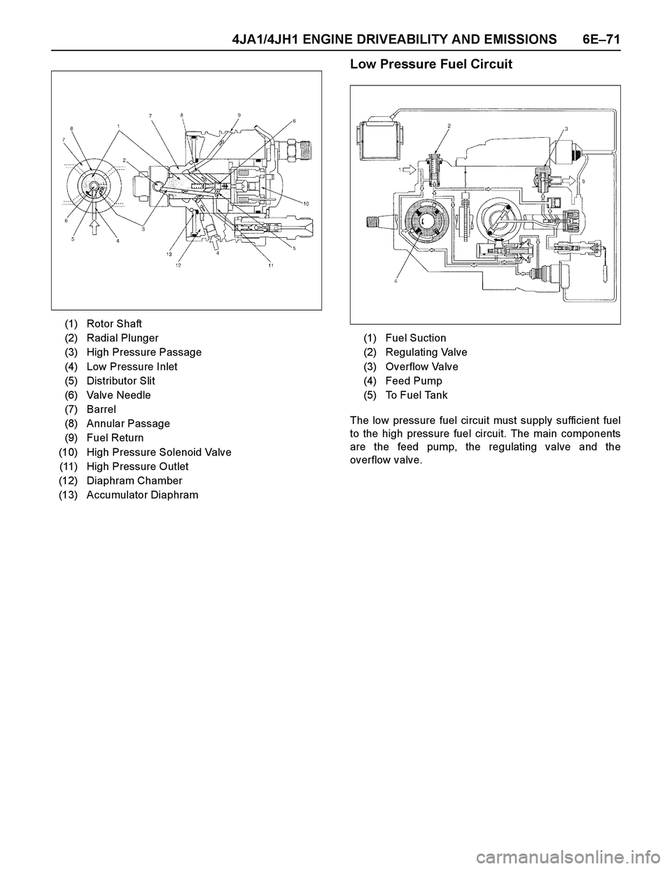
Low Pressure Fuel Circuit
The low pressure fuel circuit must supply sufficient fuel
to the high pressure fuel circuit. The main components
are the feed pump, the regulating valve and the
overflow valve. (1) Rotor Shaft
(2) Radial Plunger
(3) High Pressure Passage
(4) Low Pressure Inlet
(5) Distributor Slit
(6) Valve Needle
(7) Barrel
(8) Annular Passage
(9) Fuel Return
(10) High Pressure Solenoid Valve
(11) High Pressure Outlet
(12) Diaphram Chamber
(13) Accumulator Diaphram
(1) Fuel Suction
(2) Regulating Valve
(3) Overflow Valve
(4) Feed Pump
(5) To Fuel Tank
Page 1444 of 4264
6E–72 4JA1/4JH1 ENGINE DRIVEABILITY AND EMISSIONS
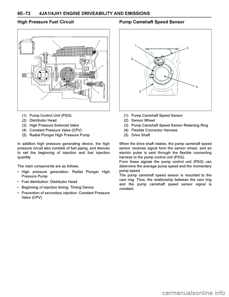
High Pressure Fuel Circuit
In addition high pressure generating device, the high
pressure circuit also consists of fuel piping, and devices
to set the beginning of injection and fuel injection
quantity.
The main components are as follows.
High pressure generation: Radial Plunger High
Pressure Pump
Fuel distribution: Distributor Head
Beginning of injection timing: Timing Device
Prevention of secondary injection: Constant Pressure
Valve (CPV)
Pump Camshaft Speed Sensor
When the drive shaft rotates, the pump camshaft speed
sensor receives signal form the sensor wheel, and an
electric pulse is sent through the flex ible connecting
harness to the pump control unit (PSG).
From these signals the pump control unit (PSG) can
determine the average pump speed and the momentary
pump speed.
The pump camshaft speed sensor is mounted to the
cam ring. Thus, the relationship between the cam ring
and the pump camshaft speed sensor signal is
constant. (1) Pump Control Unit (PSG)
(2) Distributor Head
(3) High Pressure Solenoid Valve
(4) Constant Pressure Valve (CPV)
(5) Radial Plunger High Pressure Pump
(1) Pump Camshaft Speed Sensor
(2) Sensor Wheel
(3) Pump Camshaft Speed Sensor Retaining Ring
(4) Flex ible Connector Harness
(5) Drive Shaft
Page 1445 of 4264
4JA1/4JH1 ENGINE DRIVEABILITY AND EMISSIONS 6E–73
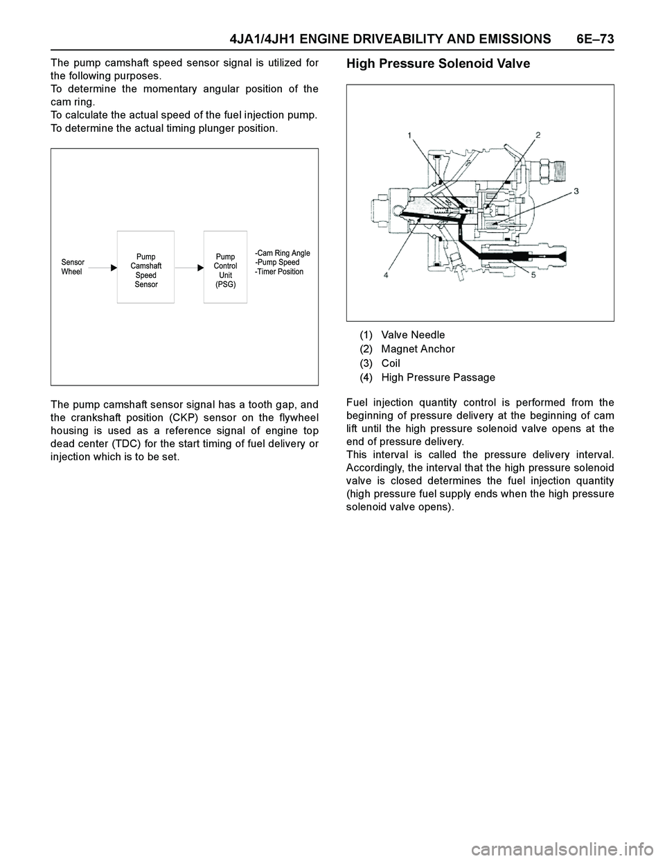
The pump camshaft speed sensor signal is utilized for
the following purposes.
To determine the momentary angular position of the
cam ring.
To calculate the actual speed of the fuel injection pump.
To determine the actual timing plunger position.
The pump camshaft sensor signal has a tooth gap, and
the crankshaft position (CKP) sensor on the flywheel
housing is used as a reference signal of engine top
dead center (TDC) for the start timing of fuel delivery or
injection which is to be set.High Pressure Solenoid Valve
Fuel injection quantity control is performed from the
beginning of pressure delivery at the beginning of cam
lift until the high pressure solenoid valve opens at the
end of pressure delivery.
This interval is called the pressure delivery interval.
Accordingly, the interval that the high pressure solenoid
valve is closed determines the fuel injection quantity
(high pressure fuel supply ends when the high pressure
solenoid valve opens).
-Cam Ring Angle
Sensor -Pump Speed
Wheel -Timer PositionPump
Control
Unit
(PSG)Pump
Camshaft
Speed
Sensor
(1) Valve Needle
(2) Magnet Anchor
(3) Coil
(4) High Pressure Passage
Page 1446 of 4264
6E–74 4JA1/4JH1 ENGINE DRIVEABILITY AND EMISSIONS
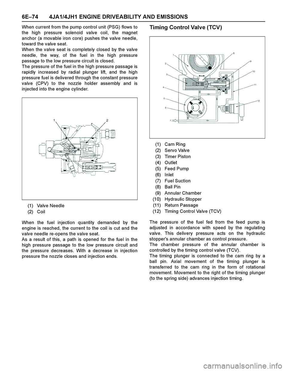
When current from the pump control unit (PSG) flows to
the high pressure solenoid valve coil, the magnet
anchor (a movable iron core) pushes the valve needle,
toward the valve seat.
When the valve seat is completely closed by the valve
needle, the way, of the fuel in the high pressure
passage to the low pressure circuit is closed.
The pressure of the fuel in the high pressure passage is
rapidly increased by radial plunger lift, and the high
pressure fuel is delivered through the constant pressure
valve (CPV) to the nozzle holder assembly and is
injected into the engine cylinder.
When the fuel injection quantity demanded by the
engine is reached, the current to the coil is cut and the
valve needle re-opens the valve seat.
As a result of this, a path is opened for the fuel in the
high pressure passage to the low pressure circuit and
the pressure decreases. With a decrease in injection
pressure the nozzle closes and injection ends.Timing Control Valve (TCV)
The pressure of the fuel fed from the feed pump is
adjusted in accordance with speed by the regulating
valve. This delivery pressure acts on the hydraulic
stopper's annular chamber as control pressure.
The chamber pressure of the annular chamber is
controlled by the timing control valve (TCV).
The timing plunger is connected to the cam ring by a
ball pin. Ax ial movement of the timing plunger is
transferred to the cam ring in the form of rotational
movement. Movement to the right of the timing plunger
(to the spring side) advances injection timing. (1) Valve Needle
(2) Coil
(1) Cam Ring
(2) Servo Valve
(3) Timer Piston
(4) Outlet
(5) Feed Pump
(6) Inlet
(7) Fuel Suction
(8) Ball Pin
(9) Annular Chamber
(10) Hydraulic Stopper
(11) Return Passage
(12) Timing Control Valve (TCV)
Page 1447 of 4264
4JA1/4JH1 ENGINE DRIVEABILITY AND EMISSIONS 6E–75
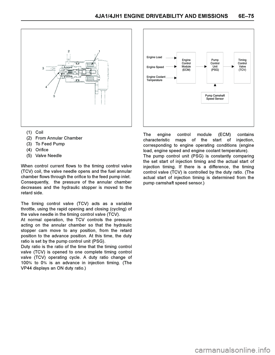
When control current flows to the timing control valve
(TCV) coil, the valve needle opens and the fuel annular
chamber flows through the orifice to the feed pump inlet.
Consequently, the pressure of the annular chamber
decreases and the hydraulic stopper is moved to the
retard side.
The timing control valve (TCV) acts as a variable
throttle, using the rapid opening and closing (cycling) of
the valve needle in the timing control valve (TCV).
At normal operation, the TCV controls the pressure
acting on the annular chamber so that the hydraulic
stopper cam move to any position, from the retard
position to the advance position. At this time, the duty
ratio is set by the pump control unit (PSG).
Duty ratio is the ratio of the time that the timing control
valve (TCV) is opened to one complete timing control
valve (TCV) operating cycle. A duty ratio change of
100% to 0% is an advance in injection timing. (The
VP44 displays an ON duty ratio.)The engine control module (ECM) contains
characteristic maps of the start of injection,
corresponding to engine operating conditions (engine
load, engine speed and engine coolant temperature).
The pump control unit (PSG) is constantly comparing
the set start of injection timing and the actual start of
injection timing. If there is a difference, the timing
control valve (TCV) is controlled by the duty ratio. (The
actual start of injection timing is determined from the
pump camshaft speed sensor.) (1) Coil
(2) From Annular Chamber
(3) To Feed Pump
(4) Orifice
(5) Valve Needle
Engine Load
Engine Speed
Engine Coolant
TemperatureEngine
Control
Module
(ECM)Pump
Control
Unit
(PSG)
Pump Camshaft
Speed Sensor
Timing
Control
Valve
(TCV)
Page 1454 of 4264
6E–82 4JA1/4JH1 ENGINE DRIVEABILITY AND EMISSIONS
GENERAL SERVICE INFORMATION
Serviceability Issues
Non-OEM Parts
All of the OBD diagnostics have been calibrated to run
with OEM parts. Accordingly, if commercially sold
sensor or switch is installed, it makes a wrong diagnosis
and turns on the check engine lamp.
Aftermarket electronics, such as cellular phones,
stereos, and anti-theft devices, may radiate EMI into the
control system if they are improperly installed. This may
cause a false sensor reading and turn on the check
engine lamp.
Poor Vehicle Maintenance
The sensitivity of OBD diagnostics will cause the check
engine lamp to turn on if the vehicle is not maintained
properly. Restricted oil filters, fuel filters, and crankcase
deposits due to lack of oil changes or improper oil
viscosity can trigger actual vehicle faults that were not
previously monitored prior to OBD. Poor vehicle
maintenance can not be classified as a “non-vehicle
fault”, but with the sensitivity of OBD diagnostics,
vehicle maintenance schedules must be more closely
followed.
Related System Faults
Many of the OBD system diagnostics will not run if the
ECM detects a fault on a related system or component.
Visual/Physical Engine Compartment
Inspection
Perform a careful visual and physical engine
compartment inspection when performing any
diagnostic procedure or diagnosing the cause of an
emission test failure. This can often lead to repairing a
problem without further steps. Use the following
guidelines when performing a visual/physical
inspection:
Inspect all vacuum hoses for punches, cuts,
disconnects, and correct routing.
Inspect hoses that are difficult to see behind other
components.
Inspect all wires in the engine compartment for
proper connections, burned or chafed spots, pinched
wires, contact with sharp edges or contact with hot
exhaust manifolds or pipes.
Basic Knowledge of Tools Required
NOTE: Lack of basic knowledge of this powertrain
when performing diagnostic procedures could result in
an incorrect diagnosis or damage to powertrain
components. Do not attempt to diagnose a powertrain
problem without this basic knowledge.
A basic understanding of hand tools is necessary to
effectively use this section of the Service Manual.
ON-BOARD DIAGNOSTIC (OBD)
On-Board Diagnostic (Self Diagnosis
System) Tests
A diagnostic test is a series of steps, the result of which
is a pass or fail reported to the diagnostic ex ecutive.
When a diagnostic test reports a pass result, the
diagnostic ex ecutive records the following data:
The diagnostic test has been completed since the
last ignition cycle.
The diagnostic test has passed during the current
ignition cycle.
The fault identified by the diagnostic test is not
currently active.
When a diagnostic test reports a fail result, the
diagnostic ex ecutive records the following data:
The diagnostic test has been completed since the
last ignition cycle.
The fault identified by the diagnostic test is currently
active.
The fault has been active during this ignition cycle.
The operating conditions at the time of the failure.
The Diagnostic Executive
The Diagnostic Executive is a unique segment of
software which is designed to coordinate and prioritize
the diagnostic procedures as well as define the protocol
for recording and displaying their results. The main
responsibilities of the Diagnostic Ex ecutive are listed as
follow s:
Commanding the check engine lamp on and off
DTC logging and clearing
Current status information on each diagnostic
Diagnostic Information
The diagnostic charts and functional checks are
designed to locate a faulty circuit or component through
a process of logical decisions. The charts are prepared
with the requirement that the vehicle functioned
correctly at the time of assembly and that there are not
multiple faults present.
There is a continuous self-diagnosis on certain control
functions. This diagnostic capability is complemented
by the diagnostic procedures contained in this manual.
The language of communicating the source of the
malfunction is a system of diagnostic trouble codes.
When a malfunction is detected by the control module, a
diagnostic trouble code is set and the check engine
lamp is illuminated.
Check Engine Lamp
The check engine lamp looks the same as the check
engine lamp you are already familiar with, the “Check
Engine” lamp.
Basically, the check engine lamp is turned on when the