2004 ISUZU TF SERIES fuel
[x] Cancel search: fuelPage 1460 of 4264
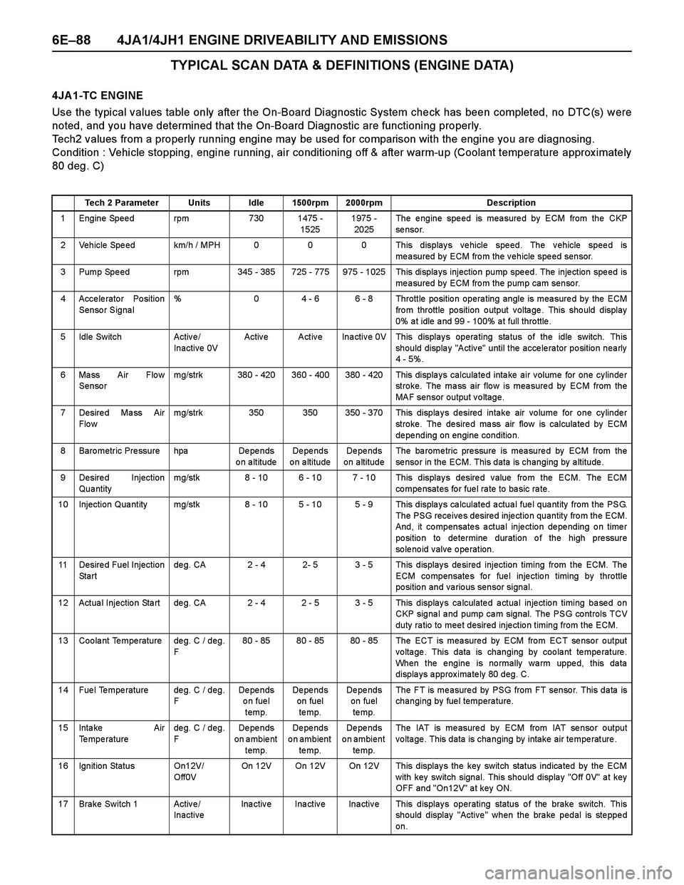
6E–88 4JA1/4JH1 ENGINE DRIVEABILITY AND EMISSIONS
TYPICAL SCAN DATA & DEFINITIONS (ENGINE DATA)
4JA 1-TC ENGINE
Use the typical values table only after the On-Board Diagnostic System check has been completed, no DTC(s) were
noted, and you have determined that the On-Board Diagnostic are functioning properly.
Tech2 values from a properly running engine may be used for comparison with the engine you are diagnosing.
Condition : Vehicle stopping, engine running, air conditioning off & after warm-up (Coolant temperature approx imately
80 deg. C)
Tech 2 Parameter Units Idle 1500rpm 2000rpm Description
1 Engine Speed rpm 730 1475 -
15251975 -
2025The engine speed is measured by ECM from the CKP
se nso r.
2 Vehicle Speed km/h / MPH 0 0 0 This displays vehicle speed. The vehicle speed is
measured by ECM from the vehicle speed sensor.
3 Pump Spe ed rpm 345 - 385 725 - 775 975 - 1025 This displa ys injectio n pump spe ed. The inje ction spe ed is
measured by ECM from the pump cam sensor.
4 Accelerator Position
Sensor Signal% 0 4 - 6 6 - 8 Throttle position operating angle is measured by the ECM
fro m throttle po sition o utput v olta ge . This sho uld display
0% a t idle a nd 99 - 100% a t full thro ttle .
5 Idle Switch Activ e /
Inactive 0VActive Active Inactive 0V This displays operating status of the idle switch. This
should display "Active" until the accelerator position nearly
4 - 5%.
6 Mass Air Flow
Sensormg/strk 380 - 420 360 - 400 380 - 420 This displays calculated intake air volume for one cylinder
stroke. The mass air flow is measured by ECM from the
MAF sensor output voltage.
7 Desire d Ma ss Air
Flo wmg/strk 350 350 350 - 370 This displays desired intake air volume for one cylinder
stroke. The desired mass air flow is calculated by ECM
de pe nding on engine conditio n.
8 Baro metric Pre ssure hpa De pe nds
on altitudeDe pe nds
o n a ltitudeDe pe nds
on altitudeThe ba rome tric pre ssure is mea sure d by ECM from the
sensor in the ECM. This data is changing by altitude.
9 Desired Injection
Qua ntitymg/stk 8 - 10 6 - 10 7 - 10 This displays desired value from the ECM. The ECM
co mpe nsates fo r fue l ra te to ba sic ra te.
10 Injection Qua ntity mg/stk 8 - 10 5 - 10 5 - 9 This displa y s ca lculated a ctua l fue l qua ntity from the PSG.
The PSG receives desired injection quantity from the ECM.
And, it compensates actual injection depending on timer
po sitio n to de termine duration o f the high pre ssure
solenoid valve operation.
11 Desire d Fuel Injection
St a r tde g. CA 2 - 4 2- 5 3 - 5 This display s de sired injection timing from the ECM. The
ECM compensates for fuel injection timing by throttle
position and various sensor signal.
12 Actua l Injectio n Sta rt de g. CA 2 - 4 2 - 5 3 - 5 This display s ca lculate d a ctua l inje ctio n timing ba se d o n
CKP signa l a nd pump ca m signal. The PSG controls TCV
duty ra tio to mee t desired inje ctio n timing from the ECM.
13 Coolant Temperature deg. C / deg.
F80 - 85 80 - 85 80 - 85 The ECT is measured by ECM from ECT sensor output
voltage. This data is changing by coolant temperature.
When the engine is normally warm upped, this data
displays approximately 80 deg. C.
14 Fuel Temperature deg. C / deg.
FDe pe nds
on fuel
temp.De pe nds
on fuel
te mp.De pe nds
on fuel
te mp.The FT is measured by PSG from FT sensor. This data is
changing by fuel temperature.
15 Inta ke Air
Temperaturedeg. C / deg.
FDe pe nds
on ambient
temp.De pe nds
on ambient
te mp.De pe nds
on ambient
te mp.The IAT is measured by ECM from IAT sensor output
voltage. This data is changing by intake air temperature.
16 Ignition Status On12V/
Off0VOn 12V On 12V On 12V This displays the key switch status indicated by the ECM
with key switch signal. This should display "Off 0V" at key
OFF and "On12V" at key ON.
17 Brake Switch 1 Active/
InactiveInactive Inactive Inactive This displays operating status of the brake switch. This
should display "Active" when the brake pedal is stepped
on.
Page 1462 of 4264
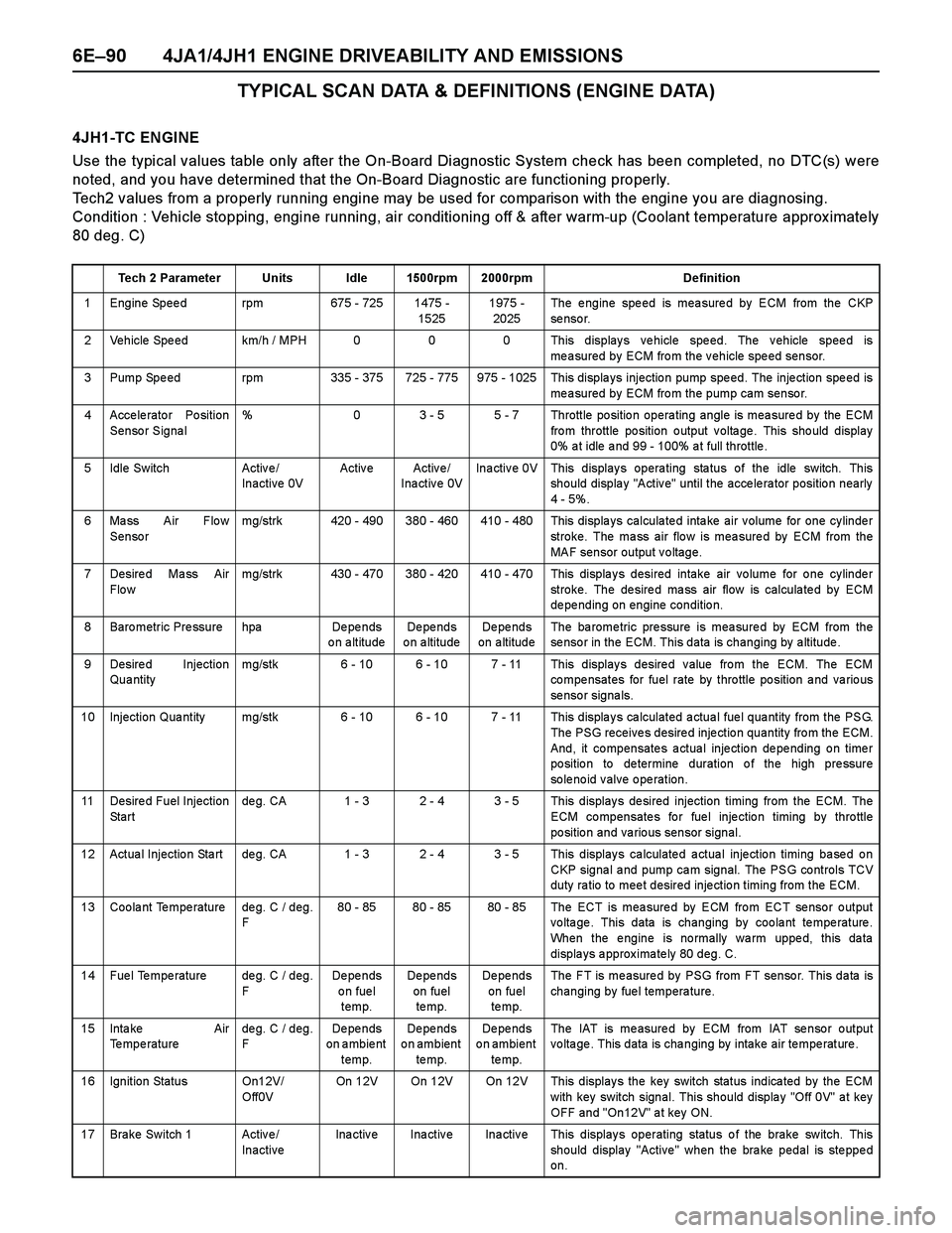
6E–90 4JA1/4JH1 ENGINE DRIVEABILITY AND EMISSIONS
TYPICAL SCAN DATA & DEFINITIONS (ENGINE DATA)
4JH1-TC ENGINE
Use the typical values table only after the On-Board Diagnostic System check has been completed, no DTC(s) were
noted, and you have determined that the On-Board Diagnostic are functioning properly.
Tech2 values from a properly running engine may be used for comparison with the engine you are diagnosing.
Condition : Vehicle stopping, engine running, air conditioning off & after warm-up (Coolant temperature approx imately
80 deg. C)
Tech 2 Parameter Units Idle 1500rpm 2000rpm Definition
1 Engine Speed rpm 675 - 725 1475 -
15251975 -
2025The engine speed is measured by ECM from the CKP
se nso r.
2 Vehicle Speed km/h / MPH 0 0 0 This displays vehicle speed. The vehicle speed is
measured by ECM from the vehicle speed sensor.
3 Pump Spe ed rpm 335 - 375 725 - 775 975 - 1025 This displa ys injectio n pump spe ed. The inje ction spe ed is
measured by ECM from the pump cam sensor.
4 Accelerator Position
Sensor Signal% 0 3 - 5 5 - 7 Throttle position operating angle is measured by the ECM
fro m throttle po sition o utput v olta ge . This sho uld display
0% a t idle a nd 99 - 100% a t full throttle .
5 Idle Switch Activ e /
Inactive 0VActive Active/
Inactive 0VInactive 0V This displays operating status of the idle switch. This
should display "Active" until the accelerator position nearly
4 - 5%.
6 Mass Air Flow
Sensormg/strk 420 - 490 380 - 460 410 - 480 This displays calculated intake air volume for one cylinder
stroke. The mass air flow is measured by ECM from the
MAF sensor output voltage.
7 Desire d Ma ss Air
Flo wmg/strk 430 - 470 380 - 420 410 - 470 This displays desired intake air volume for one cylinder
stroke. The desired mass air flow is calculated by ECM
de pe nding on engine conditio n.
8 Baro metric Pre ssure hpa De pe nds
on altitudeDe pe nds
o n a ltitudeDe pe nds
on altitudeThe ba rome tric pre ssure is mea sure d by ECM from the
sensor in the ECM. This data is changing by altitude.
9 Desired Injection
Qua ntitymg/stk 6 - 10 6 - 10 7 - 11 This displays desired value from the ECM. The ECM
co mpe nsates for fuel rate by thro ttle po sition a nd va rio us
se nso r signa ls.
10 Injection Qua ntity mg/stk 6 - 10 6 - 10 7 - 11 This displa y s ca lculated a ctua l fue l qua ntity from the PSG.
The PSG receives desired injection quantity from the ECM.
And, it compensates actual injection depending on timer
po sitio n to de termine duration o f the high pre ssure
solenoid valve operation.
11 Desire d Fuel Injection
St a r tde g. CA 1 - 3 2 - 4 3 - 5 This display s de sired injection timing from the ECM. The
ECM compensates for fuel injection timing by throttle
position and various sensor signal.
12 Actua l Injectio n Sta rt de g. CA 1 - 3 2 - 4 3 - 5 This display s ca lculate d a ctua l inje ctio n timing ba se d o n
CKP signa l a nd pump ca m signal. The PSG controls TCV
duty ra tio to mee t desired inje ctio n timing from the ECM.
13 Coolant Temperature deg. C / deg.
F80 - 85 80 - 85 80 - 85 The ECT is measured by ECM from ECT sensor output
voltage. This data is changing by coolant temperature.
When the engine is normally warm upped, this data
displays approximately 80 deg. C.
14 Fuel Temperature deg. C / deg.
FDe pe nds
on fuel
temp.De pe nds
on fuel
te mp.De pe nds
on fuel
te mp.The FT is measured by PSG from FT sensor. This data is
changing by fuel temperature.
15 Inta ke Air
Temperaturedeg. C / deg.
FDe pe nds
on ambient
temp.De pe nds
on ambient
te mp.De pe nds
on ambient
te mp.The IAT is measured by ECM from IAT sensor output
voltage. This data is changing by intake air temperature.
16 Ignition Status On12V/
Off0VOn 12V On 12V On 12V This displays the key switch status indicated by the ECM
with key switch signal. This should display "Off 0V" at key
OFF and "On12V" at key ON.
17 Brake Switch 1 Active/
InactiveInactive Inactive Inactive This displays operating status of the brake switch. This
should display "Active" when the brake pedal is stepped
on.
Page 1486 of 4264
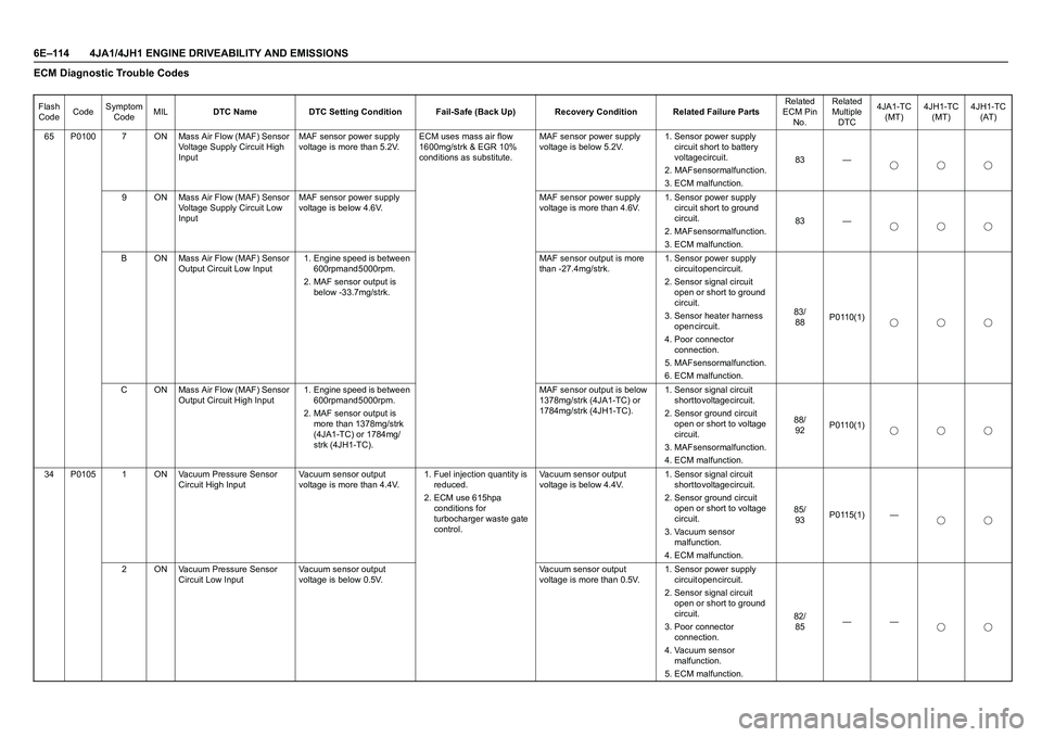
6E–114 4JA1/4JH1 ENGINE DRIVEABILITY AND EMISSIONSECM Diagnostic Trouble CodesFlash
CodeCodeSymptom
CodeMILDTC Name DTC Setting Condition Fail-Safe (Back Up) Recovery Condition Related Failure PartsRelated
ECM Pin
No.Related
Multiple
DTC4JA1-TC
(MT)4JH1-TC
(MT)4JH1-TC
(AT)
65 P0100 7 ON Mass Air Flow (MAF) Sensor
Voltage Supply Circuit High
InputMAF sensor power supply
voltage is more than 5.2V.ECM uses mass air flow
1600mg/strk & EGR 10%
conditions as substitute.MAF sensor power supply
voltage is below 5.2V.1. Sensor power supply
circuit short to battery
voltage circuit.
2. MAF sensor malfunction.
3. ECM malfunction.83 —
9 ON Mass Air Flow (MAF) Sensor
Voltage Supply Circuit Low
InputMAF sensor power supply
voltage is below 4.6V.MAF sensor power supply
voltage is more than 4.6V.1. Sensor power supply
circuit short to ground
c i r c u i t .
2. MAF sensor malfunction.
3. ECM malfunction.83 —
B ON Mass Air Flow (MAF) Sensor
Output Circuit Low Input1. Engine speed is between
600rpm and 5000rpm.
2. MAF sensor output is
below -33.7mg/strk.MAF sensor output is more
than -27.4mg/strk.1. Sensor power supply
circuit open circuit.
2. Sensor signal circuit
open or short to ground
c i r c u i t .
3. Sensor heater harness
o p e n c i r c u i t .
4. Poor connector
c o n n e c t i o n .
5. MAF sensor malfunction.
6. ECM malfunction.8 3 /
88P0110(1)
C ON Mass Air Flow (MAF) Sensor
Output Circuit High Input1. Engine speed is between
600rpm and 5000rpm.
2. MAF sensor output is
more than 1378mg/strk
(4JA1-TC) or 1784mg/
strk (4JH1-TC).MAF sensor output is below
1378mg/strk (4JA1-TC) or
1784mg/strk (4JH1-TC).1. Sensor signal circuit
short to voltage circuit.
2. Sensor ground circuit
open or short to voltage
c i r c u i t .
3. MAF sensor malfunction.
4. ECM malfunction.8 8 /
92P0110(1)
34 P0105 1 ON Vacuum Pressure Sensor
Circuit High InputVacuum sensor output
voltage is more than 4.4V.1. Fuel injection quantity is
r e d u c e d .
2. ECM use 615hpa
conditions for
turbocharger waste gate
control.Vacuum sensor output
voltage is below 4.4V.1. Sensor signal circuit
short to voltage circuit.
2. Sensor ground circuit
open or short to voltage
c i r c u i t .
3. Vacuum sensor
m a l f u n c t i o n .
4. ECM malfunction.8 5 /
93P0115(1) —
2 ON Vacuum Pressure Sensor
Circuit Low InputVacuum sensor output
voltage is below 0.5V.Vacuum sensor output
voltage is more than 0.5V.1. Sensor power supply
circuit open circuit.
2. Sensor signal circuit
open or short to ground
c i r c u i t .
3. Poor connector
c o n n e c t i o n .
4. Vacuum sensor
m a l f u n c t i o n .
5. ECM malfunction.8 2 /
85——
Page 1487 of 4264
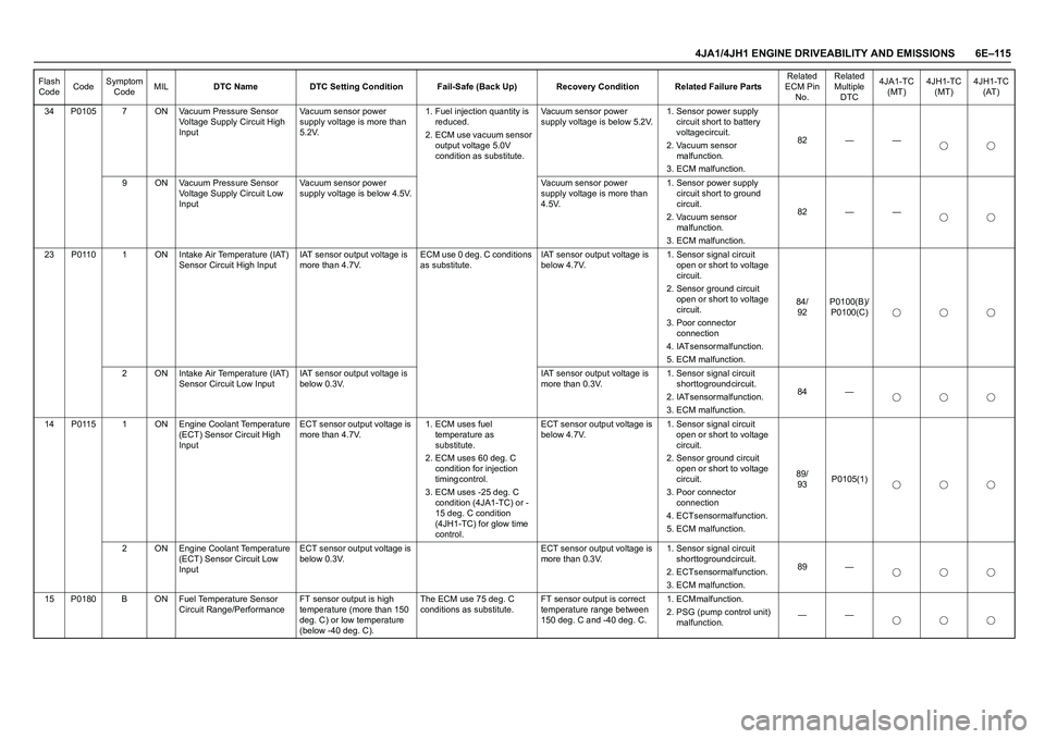
4JA1/4JH1 ENGINE DRIVEABILITY AND EMISSIONS 6E–115
34 P0105 7 ON Vacuum Pressure Sensor
Voltage Supply Circuit High
InputVacuum sensor power
supply voltage is more than
5.2V.1. Fuel injection quantity is
r e d u c e d .
2. ECM use vacuum sensor
output voltage 5.0V
condition as substitute.Vacuum sensor power
supply voltage is below 5.2V.1. Sensor power supply
circuit short to battery
voltage circuit.
2. Vacuum sensor
m a l f u n c t i o n .
3. ECM malfunction.82 — —
9 ON Vacuum Pressure Sensor
Voltage Supply Circuit Low
InputVacuum sensor power
supply voltage is below 4.5V.Vacuum sensor power
supply voltage is more than
4.5V.1. Sensor power supply
circuit short to ground
c i r c u i t .
2. Vacuum sensor
m a l f u n c t i o n .
3. ECM malfunction.82 — —
23 P0110 1 ON Intake Air Temperature (IAT)
Sensor Circuit High InputIAT sensor output voltage is
more than 4.7V.ECM use 0 deg. C conditions
as substitute.IAT sensor output voltage is
below 4.7V.1. Sensor signal circuit
open or short to voltage
c i r c u i t .
2. Sensor ground circuit
open or short to voltage
c i r c u i t .
3. Poor connector
c o n n e c t i o n
4. IAT sensor malfunction.
5. ECM malfunction.8 4 /
92P0100(B)/
P0100(C)
2 ON Intake Air Temperature (IAT)
Sensor Circuit Low InputIAT sensor output voltage is
below 0.3V.IAT sensor output voltage is
more than 0.3V.1. Sensor signal circuit
short to ground circuit.
2. IAT sensor malfunction.
3. ECM malfunction.84 —
14 P0115 1 ON Engine Coolant Temperature
(ECT) Sensor Circuit High
InputECT sensor output voltage is
more than 4.7V.1. ECM uses fuel
temperature as
s u b s t i t u t e .
2. ECM uses 60 deg. C
condition for injection
t i m i n g c o n t r o l .
3. ECM uses -25 deg. C
condition (4JA1-TC) or -
15 deg. C condition
(4JH1-TC) for glow time
control.ECT sensor output voltage is
below 4.7V.1. Sensor signal circuit
open or short to voltage
c i r c u i t .
2. Sensor ground circuit
open or short to voltage
c i r c u i t .
3. Poor connector
c o n n e c t i o n
4. ECT sensor malfunction.
5. ECM malfunction.8 9 /
93P0105(1)
2 ON Engine Coolant Temperature
(ECT) Sensor Circuit Low
InputECT sensor output voltage is
below 0.3V.ECT sensor output voltage is
more than 0.3V.1. Sensor signal circuit
short to ground circuit.
2. ECT sensor malfunction.
3. ECM malfunction.89 —
15 P0180 B ON Fuel Temperature Sensor
Circuit Range/PerformanceFT sensor output is high
temperature (more than 150
deg. C) or low temperature
(below -40 deg. C).The ECM use 75 deg. C
conditions as substitute.FT sensor output is correct
temperature range between
150 deg. C and -40 deg. C.1 . E C M m a l f u n c t i o n .
2. PSG (pump control unit)
malfunction.—— Flash
CodeCodeSymptom
CodeMILDTC Name DTC Setting Condition Fail-Safe (Back Up) Recovery Condition Related Failure PartsRelated
ECM Pin
No.Related
Multiple
DTC4JA1-TC
(MT)4JH1-TC
(MT)4JH1-TC
(AT)
Page 1488 of 4264
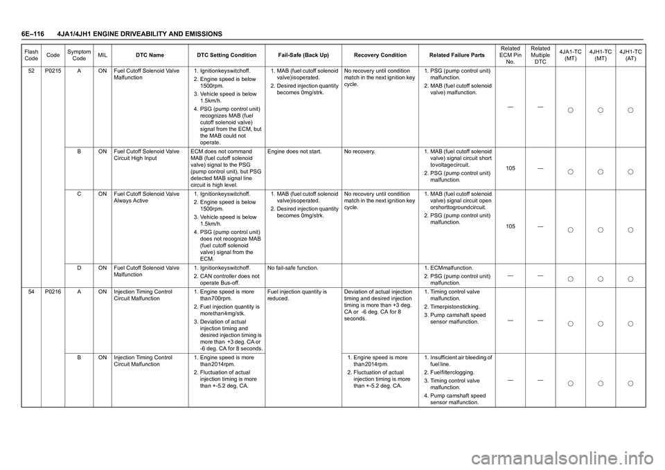
6E–116 4JA1/4JH1 ENGINE DRIVEABILITY AND EMISSIONS
52 P0215 A ON Fuel Cutoff Solenoid Valve
Malfunction1. Ignition key switch off.
2. Engine speed is below
1 5 0 0 r p m .
3. Vehicle speed is below
1 . 5 k m / h .
4. PSG (pump control unit)
recognizes MAB (fuel
cutoff solenoid valve)
signal from the ECM, but
the MAB could not
operate. 1. MAB (fuel cutoff solenoid
v a l v e ) i s o p e r a t e d .
2. Desired injection quantity
becomes 0mg/strk.No recovery until condition
match in the next ignition key
cycle.1. PSG (pump control unit)
m a l f u n c t i o n .
2. MAB (fuel cutoff solenoid
valve) malfunction.
——
B ON Fuel Cutoff Solenoid Valve
Circuit High InputECM does not command
MAB (fuel cutoff solenoid
valve) signal to the PSG
(pump control unit), but PSG
detected MAB signal line
circuit is high level.Engine does not start. No recovery. 1. MAB (fuel cutoff solenoid
valve) signal circuit short
t o v o l t a g e c i r c u i t .
2. PSG (pump control unit)
malfunction.105 —
C ON Fuel Cutoff Solenoid Valve
Always Active1. Ignition key switch off.
2. Engine speed is below
1 5 0 0 r p m .
3. Vehicle speed is below
1 . 5 k m / h .
4. PSG (pump control unit)
does not recognize MAB
(fuel cutoff solenoid
valve) signal from the
ECM. 1. MAB (fuel cutoff solenoid
v a l v e ) i s o p e r a t e d .
2. Desired injection quantity
becomes 0mg/strk.No recovery until condition
match in the next ignition key
cycle.1. MAB (fuel cutoff solenoid
valve) signal circuit open
or short to ground circuit.
2. PSG (pump control unit)
malfunction.
105 —
D ON Fuel Cutoff Solenoid Valve
Malfunction1. Ignition key switch off.
2. CAN controller does not
operate Bus-off.N o f a i l - s a f e f u n c t i o n . 1 . E C M m a l f u n c t i o n .
2. PSG (pump control unit)
malfunction.——
54 P0216 A ON Injection Timing Control
Circuit Malfunction1. Engine speed is more
t h a n 7 0 0 r p m .
2. Fuel injection quantity is
more than 4mg/stk.
3. Deviation of actual
injection timing and
desired injection timing is
more than +3 deg. CA or
-6 deg. CA for 8 seconds.Fuel injection quantity is
reduced.Deviation of actual injection
timing and desired injection
timing is more than +3 deg.
CA or -6 deg. CA for 8
seconds.1. Timing control valve
m a l f u n c t i o n .
2 . T i m e r p i s t o n s t i c k i n g .
3. Pump camshaft speed
sensor malfunction.——
B ON Injection Timing Control
Circuit Malfunction 1. Engine speed is more
t h a n 2 0 1 4 r p m .
2. Fluctuation of actual
injection timing is more
than +-5.2 deg. CA.1. Engine speed is more
than 2014rpm.
2. Fluctuation of actual
injection timing is more
than +-5.2 deg. CA.1. Insufficient air bleeding of
f u e l l i n e .
2. Fuel filter clogging.
3. Timing control valve
m a l f u n c t i o n .
4. Pump camshaft speed
sensor malfunction. —— Flash
CodeCodeSymptom
CodeMILDTC Name DTC Setting Condition Fail-Safe (Back Up) Recovery Condition Related Failure PartsRelated
ECM Pin
No.Related
Multiple
DTC4JA1-TC
(MT)4JH1-TC
(MT)4JH1-TC
(AT)
Page 1489 of 4264
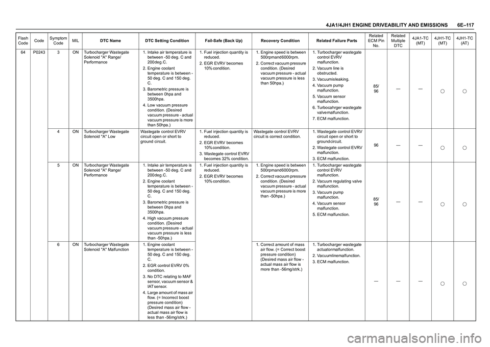
4JA1/4JH1 ENGINE DRIVEABILITY AND EMISSIONS 6E–117
64 P0243 3 ON Turbocharger Wastegate
Solenoid "A" Range/
Performance1. Intake air temperature is
between -50 deg. C and
2 0 0 d e g . C .
2. Engine coolant
temperature is between -
50 deg. C and 150 deg.
C .
3. Barometric pressure is
between 0hpa and
3 5 0 0 h p a .
4. Low vacuum pressure
condition. (Desired
vacuum pressure - actual
vacuum pressure is more
than 50hpa.)1. Fuel injection quantity is
r e d u c e d .
2. EGR EVRV becomes
1 0 % c o n d i t i o n . 1. Engine speed is between
500rpm and 6000rpm.
2. Correct vacuum pressure
condition. (Desired
vacuum pressure - actual
vacuum pressure is less
than 50hpa.)1. Turbocharger wastegate
control EVRV
m a l f u n c t i o n .
2. Vacuum line is
o b s t r u c t e d .
3. Vacuum is leaking.
4. Vacuum pump
m a l f u n c t i o n .
5. Vacuum sensor
m a l f u n c t i o n .
6. Turbocahrger wastegate
v a l v e m a l f u n c t i o n .
7. ECM malfunction.8 5 /
96——
4 ON Turbocharger Wastegate
Solenoid "A" Low Wastegate control EVRV
circuit open or short to
ground circuit.1. Fuel injection quantity is
r e d u c e d .
2. EGR EVRV becomes
1 0 % c o n d i t i o n .
3. Wastegate control EVRV
becomes 32% condition.Wastegate control EVRV
circuit is correct condition.1. Wastegate control EVRV
circuit open or short to
g r o u n d c i r c u i t .
2. Wastegate control EVRV
m a l f u n c t i o n .
3. ECM malfunction.96 — —
5 ON Turbocharger Wastegate
Solenoid "A" Range/
Performance1. Intake air temperature is
between -50 deg. C and
2 0 0 d e g . C .
2. Engine coolant
temperature is between -
50 deg. C and 150 deg.
C .
3. Barometric pressure is
between 0hpa and
3 5 0 0 h p a .
4. High vacuum pressure
condition. (Desired
vacuum pressure - actual
vacuum pressure is less
than -50hpa.)1. Fuel injection quantity is
r e d u c e d .
2. EGR EVRV becomes
1 0 % c o n d i t i o n . 1. Engine speed is between
500rpm and 6000rpm.
2. Correct vacuum pressure
condition. (Desired
vacuum pressure - actual
vacuum pressure is more
than -50hpa.)1. Turbocharger wastegate
control EVRV
m a l f u n c t i o n .
2. Vacuum regulating valve
m a l f u n c t i o n .
3. Vacuum pump
m a l f u n c t i o n .
4. Vacuum sensor
m a l f u n c t i o n .
5. ECM malfunction.8 5 /
96——
6 ON Turbocharger Wastegate
Solenoid "A" Malfunction1. Engine coolant
temperature is between -
50 deg. C and 150 deg.
C .
2. EGR control EVRV 0%
c o n d i t i o n .
3. No DTC relating to MAF
sensor, vacuum sensor &
I A T s e n s o r .
4. Large amount of mass air
flow. (= Incorrect boost
pressure condition)
(Desired mass air flow -
actual mass air flow is
less than -56mg/strk.)1. Correct amount of mass
air flow. (= Correct boost
pressure condition)
(Desired mass air flow -
actual mass air flow is
more than -56mg/strk.)1. Turbocharger wastegate
a c t u a t o r m a l f u n c t i o n .
2. Vacuum line malfunction.
3. ECM malfunction.
——— Flash
CodeCodeSymptom
CodeMILDTC Name DTC Setting Condition Fail-Safe (Back Up) Recovery Condition Related Failure PartsRelated
ECM Pin
No.Related
Multiple
DTC4JA1-TC
(MT)4JH1-TC
(MT)4JH1-TC
(AT)
Page 1490 of 4264
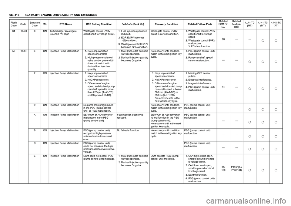
6E–118 4JA1/4JH1 ENGINE DRIVEABILITY AND EMISSIONS
64 P0243 8 ON Turbocharger Wastegate
Solenoid "A" HighWastegate control EVRV
circuit short to voltage circuit.1. Fuel injection quantity is
r e d u c e d .
2. EGR EVRV becomes
1 0 % c o n d i t i o n .
3. Wastegate control EVRV
becomes 32% condition.Wastegate control EVRV
circuit is correct condition.1. Wastegate control EVRV
circuit short to voltage
c i r c u i t .
2. Wastegate control EVRV
m a l f u n c t i o n .
3. ECM malfunction.96 — —
53 P0251 6 ON Injection Pump Malfunction 1. No pump camshaft
s p e e d s e n s o r e r r o r .
2. High pressure solenoid
valve control pulse width
does not match with
desired fuel injection
quantity. 1. MAB (fuel cutoff solenoid
v a l v e ) i s o p e r a t e d .
2. Desired injection quantity
becomes 0mg/strk.No recovery until condition
match in the next ignition key
cycle.1. PSG (pump control unit)
m a l f u n c t i o n .
2. Pump camshaft speed
sensor malfunction.——
7 ON Injection Pump Malfunction 1. No pump camshaft
s p e e d s e n s o r e r r o r .
2 . N o C K P s e n s o r e r r o r .
3. Difference of engine
speed and doubled pump
camshaft speed is more
than 720rpm (4JA1-TC)
or 690rpm (4JH1-TC). 1. No pump camshaft
s p e e d s e n s o r e r r o r .
2 . N o C K P s e n s o r e r r o r .
3. Difference of engine
speed and doubled pump
camshaft speed is below
800rpm (4JA1-TC) or
6 9 0 r p m ( 4 J H 1 - T C ) .
No recovery until in the
next ignition key cycle. 1. Missing CKP sensor
p u l s e s .
2. Electrical interference.
3. Magnetic interference.
4. PSG (pump control unit)
malfunction.91 —
9 ON Injection Pump Malfunction No pump map programmed
in the PSG (pump control
unit) or PSG malfunction.No recovery until condition
match in the next ignition key
cycle.PSG (pump control unit)
malfunction. — —
A ON Injection Pump Malfunction EEPROM or A/D converter
malfunction in the PSG
(pump control unit).Fuel injection quantity is
reduced.EEPROM or A/D converter
no malfunction in the PSG
( p u m p c o n t r o l u n i t ) .
No recovery until in the next
ignition key cycle.PSG (pump control unit)
malfunction.
——
B ON Injection Pump Malfunction PSG (pump control unit)
recognized high pressure
solenoid valve drive circuit
error.No fail-safe function. No recovery until condition
match in the next ignition key
cycle.PSG (pump control unit)
malfunction.
——
D ON Injection Pump Malfunction PSG (pump control unit)
could not measure the high
pressure solenoid valve drive
voltage.PSG (pump control unit)
malfunction.
——
E ON Injection Pump Malfunction ECM could not accept PSG
(pump control unit) message.1. MAB (fuel cutoff solenoid
v a l v e ) i s o p e r a t e d .
2. Desired injection quantity
becomes 0mg/strk.ECM accepts PSG (pump
control unit) message.1. CAN high circuit open,
short to ground or short
t o v o l t a g e c i r c u i t .
2. CAN low circuit open,
short to ground or short
t o v o l t a g e c i r c u i t .
3 . E C M m a l f u n c t i o n .
4. PSG (pump control unit)
malfunction.9 9 /
100P1650(A)/
P1651(B) Flash
CodeCodeSymptom
CodeMILDTC Name DTC Setting Condition Fail-Safe (Back Up) Recovery Condition Related Failure PartsRelated
ECM Pin
No.Related
Multiple
DTC4JA1-TC
(MT)4JH1-TC
(MT)4JH1-TC
(AT)
Page 1491 of 4264
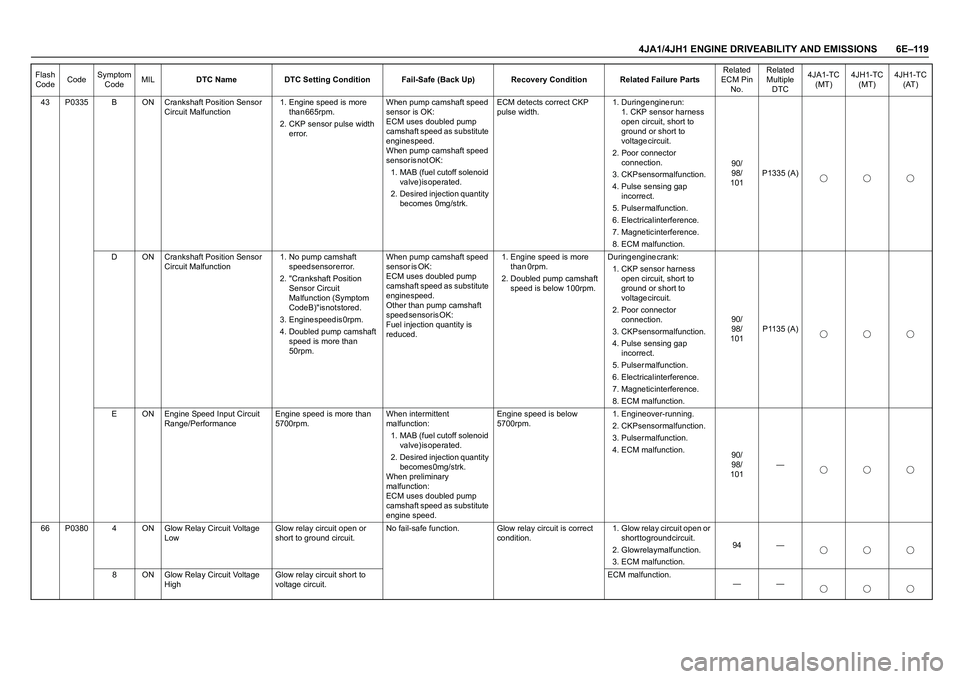
4JA1/4JH1 ENGINE DRIVEABILITY AND EMISSIONS 6E–119
43 P0335 B ON Crankshaft Position Sensor
Circuit Malfunction1. Engine speed is more
t h a n 6 6 5 r p m .
2. CKP sensor pulse width
error.When pump camshaft speed
sensor is OK:
ECM uses doubled pump
camshaft speed as substitute
engine speed.
When pump camshaft speed
s e n s o r i s n o t O K :
1. MAB (fuel cutoff solenoid
v a l v e ) i s o p e r a t e d .
2. Desired injection quantity
becomes 0mg/strk. ECM detects correct CKP
pulse width.1 . D u r i n g e n g i n e r u n :
1. CKP sensor harness
open circuit, short to
ground or short to
voltage circuit.
2. Poor connector
c o n n e c t i o n .
3. CKP sensor malfunction.
4. Pulse sensing gap
i n c o r r e c t .
5 . P u l s e r m a l f u n c t i o n .
6. Electrical interference.
7. Magnetic interference.
8. ECM malfunction.9 0 /
9 8 /
101P1335 (A)
D ON Crankshaft Position Sensor
Circuit Malfunction1. No pump camshaft
s p e e d s e n s o r e r r o r .
2. "Crankshaft Position
Sensor Circuit
Malfunction (Symptom
Code B)" is not stored.
3 . E n g i n e s p e e d i s 0 r p m .
4. Doubled pump camshaft
speed is more than
50rpm.When pump camshaft speed
s e n s o r i s O K :
ECM uses doubled pump
camshaft speed as substitute
engine speed.
Other than pump camshaft
s p e e d s e n s o r i s O K :
Fuel injection quantity is
reduced.1. Engine speed is more
than 0rpm.
2. Doubled pump camshaft
speed is below 100rpm.During engine crank:
1. CKP sensor harness
open circuit, short to
ground or short to
voltage circuit.
2. Poor connector
c o n n e c t i o n .
3. CKP sensor malfunction.
4. Pulse sensing gap
i n c o r r e c t .
5 . P u l s e r m a l f u n c t i o n .
6. Electrical interference.
7. Magnetic interference.
8. ECM malfunction.9 0 /
9 8 /
101P1135 (A)
E ON Engine Speed Input Circuit
Range/PerformanceEngine speed is more than
5700rpm.When intermittent
malfunction:
1. MAB (fuel cutoff solenoid
v a l v e ) i s o p e r a t e d .
2. Desired injection quantity
b e c o m e s 0 m g / s t r k .
When preliminary
malfunction:
ECM uses doubled pump
camshaft speed as substitute
engine speed.Engine speed is below
5700rpm.1. Engine over-running.
2. CKP sensor malfunction.
3 . P u l s e r m a l f u n c t i o n .
4. ECM malfunction.
9 0 /
9 8 /
101—
66 P0380 4 ON Glow Relay Circuit Voltage
LowGlow relay circuit open or
short to ground circuit.No fail-safe function. Glow relay circuit is correct
condition.1. Glow relay circuit open or
short to ground circuit.
2. Glow relay malfunction.
3. ECM malfunction.94 —
8 ON Glow Relay Circuit Voltage
HighGlow relay circuit short to
voltage circuit.ECM malfunction.
—— Flash
CodeCodeSymptom
CodeMILDTC Name DTC Setting Condition Fail-Safe (Back Up) Recovery Condition Related Failure PartsRelated
ECM Pin
No.Related
Multiple
DTC4JA1-TC
(MT)4JH1-TC
(MT)4JH1-TC
(AT)