Page 3470 of 4264

3B-40 POWER-ASSISTED STEERING SYSTEM
430RX005-X
14. Remove steering column cover.
15. Disconnect the wiring harness connectors located
under the steering column then remove combination
switch and SRS coil assembly.
Installation
1. Align the setting marks made when removing then
install steering wheel.
Refer to the adjustment method in case a mark is
not attached in this section.
NOTE: Confirm SRS and Horn harness connector is
fixed by the steering wheel.
RTW33BSH000601
CAUTION: Never apply force to the steering wheel in
direction of the shaft by using a hammer or othe
r
impact tools in an attempt to remove the steering
wheel. The steering shaft is designed as an energy
absorbing unit.
2. Tighten the steering wheel fixing nut to the specified
torque.
Torque: 31 - 39 N�
�� �
m (3.2 – 4.0 kg�
�� �
m/23 - 29 lb ft)
3. Support the inflator module and carefully connect the
SRS connector and horn lead. (with SRS air bag)
060R300041
4. Connect the horn leads at center of wheel. (without
SRS air bag)
NOTE: Horn leads is letting a bracket top pass.
(Plastic type steering wheel only)
RTW43BSH000301
Page 3471 of 4264
POWER-ASSISTED STEERING SYSTEM 3B-41
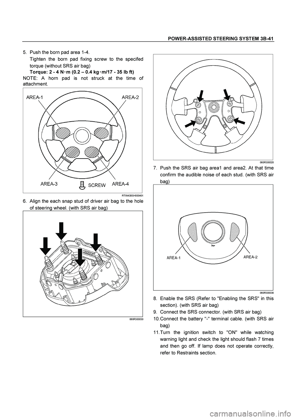
5. Push the born pad area 1-4.
Tighten the born pad fixing screw to the specifed
torque (without SRS air bag)
Torque: 2 - 4 N�
�� �m (0.2 – 0.4 kg�
�� �m/17 - 35 lb ft)
NOTE: A horn pad is not struck at the time o
f
attachment.
RTW43BSH000401
6. Align the each snap stud of driver air bag to the hole
of steering wheel. (with SRS air bag)
060R300030
060R300020
7. Push the SRS air bag area1 and area2. At that time
confirm the audible noise of each stud. (with SRS ai
r
bag)
060R300036
8. Enable the SRS (Refer to "Enabling the SRS" in this
section). (with SRS air bag)
9. Connect the SRS connector. (with SRS air bag)
10. Connect the battery "-" terminal cable. (with SRS ai
r
bag)
11. Turn the ignition switch to "ON" while watching
warning light and check the light should flash 7 times
and then go off. If lamp does not operate correctly,
refer to Restraints section.
Page 3477 of 4264

POWER-ASSISTED STEERING SYSTEM 3B-47
6. Install the driver knee bolster assembly.
7. Install the steering lower cover and engine hood
opening lever.
8. Install the steering wheel and align the setting
marks.
Refer to the adjustment method in case a mark is
not attached in this section.
NOTE: Confirm SRS and Horn harness connector is
fixed by the steering wheel.
RTW33BSH000601
CAUTION: Never apply force to the steering wheel in
direction of the shaft by using a hammer or othe
r
impact tools in an attempt to remove the steering
wheel. The steering shaft is designed as an energy
absorbing unit.
9. Tighten the steering wheel fixing nut to the specified
torque.
Torque: 31 - 39 N�
�� �m (3.2 – 4.0 kg�
�� �m/23 - 29 lb ft)
10. Support the inflator module and carefully connec
t
the SRS connector and horn lead. (with SRS air
bag)
060R300010
11. Connect the horn leads at center of wheel. (without
SRS air bag)
NOTE: Horn leads is letting a bracket top pass.
(Plastic type steering wheel only)
RTW43BSH000301
12. Push the born pad area 1-4.
Tighten the born pad fixing screw to the specifed
torque (without SRS air bag)
Torque: 2 - 4 N�
�� �
m (0.2 – 0.4 kg�
�� �
m/17 - 35 lb ft)
NOTE: A horn pad is not struck at the time o
f
attachment.
RTW43BSH00040
Page 3483 of 4264

POWER-ASSISTED STEERING SYSTEM 3B-53
825RS048
4. Install the driver knee bolster assembly.
5. Install the steering lower cover and engine hood
opening lever.
6. Install the steering wheel and align the setting marks.
Refer to the adjustment method in case a mark is no
t
attached in this section.
NOTE: Confirm SRS and Horn harness connector is
fixed by the steering wheel.
RTW33BSH000601
CAUTION: Never apply force to the steering wheel in
direction of the shaft by using a hammer or othe
r
impact tools in an attempt to remove the steering
wheel. The steering shaft is designed as an energy
absorbing unit.
7. Tighten the steering wheel fixing nut to the specified
torque.
Torque: 31 - 39 N�
�� �
m (3.2 – 4.0 kg�
�� �
m/23 - 29 lb ft)
8. Support inflator module and carefully connect the
SRS connector and horn lead, then install inflato
r
module. (with SRS air bag)
060R300010
9. Connect the horn leads at center of wheel. (without
SRS air bag)
NOTE: Horn leads is letting a bracket type pass.
(Plastic type steering wheel only)
RTW43BSH000301
Page 3484 of 4264

Torque: 2 - 4 N�
�� �m (0.2 – 0.4 kg�
�� �m/")
3B-54 POWER-ASSISTED STEERING SYSTEM
10. Push the born pad area 1-4.
Tighten the born pad fixing screw to the specifed
torque (without SRS air bag)
Torque: 2 - 4 N�
�� �m (0.2 – 0.4 kg�
�� �m/17 - 35 lb ft)
NOTE: A horn pad is not struck at the time o
f
attachment.
RTW43BSH000401
11. Align the each snap stud of driver air bag to the hole
of steering wheel. (with SRS air bag)
060R300030
060R300020
12. Push the SRS air bag area1 and area2. At that time
confirm the audible noise of each stud. (with SRS ai
r
bag)
060R300036
13. Enable the SRS (Refer to "Enabling the SRS" in this
section). (with SRS air bag)
14. Install driver knee bolster (reinforcement).
15. Install instrument panel lower cover, then install the
engine hood opening lever.
16. Connect the yellow 2-way SRS connector located
under the steering column. (with SRS air bag)
17. Connect the battery "-" terminal cable. (with SRS ai
r
bag)
System Inspection (with SRS air bag)
Turn the ignition switch to "ON" while watching warning
light.
The light should flash 7 times and then go off. If lamp
does not operate correctly, refer to Restraints section.
Page 3489 of 4264
.
431RW031
Column Universal Joint (between the
power steering unit and the steeri")
POWER-ASSISTED STEERING SYSTEM 3B-59
Check clearance between capsule and bracket. If must
be within 1mm (0.039 in).
431RW031
Column Universal Joint (between the
power steering unit and the steering shaft)
If the resistance is felt when checked by rotate the joint,
replace the lower second steering shaft.
Shaft Universal Joint (between the lower
second steering shaft and the second
steering shaft)
If the resistance is felt when checked by rotate the joint,
replace the second steering shaft assembly.
Tilt Mechanism
Tilt mechanism should moves smoothly.
While locked the tilt mechanism, be sure the steering
column latch securely by pushing the steering wheel
upward and downward.
Installation
1. Align the setting marks on the second steering shaft
and the steering column assembly (applied at
disassembly).
2. Connect the steering column assembly to the second
steering shaft. Tighten the bolts to the specified
torque.
Torque: 26 - 36 N�
�� �m (2.7 – 3.7 kg�
�� �m/20 - 27 lb ft)
3. Thread the steering column assembly through the
hole in the dashpanel. Temporarily tighten the
steering column and the second steering shaft fixing
bolt.
4. Connect the lower second steering shaft and the
second steering shaft. Tighten the universal joint
bolts to the specified torque.
Torque: 26 - 36 N�
�� �m (2.7 – 3.7 kg�
�� �m/20 - 27 lb ft)
5. Tighten the steering column fixing bolt (pedal brkt
side) to the specified torque (This bolt was
temporarily tighten in Step 3).
Torque: 18 -23 N�
�� �m (1.8 – 2.3 kg�
�� �m/13 - 17 lb ft)
6. Tighten the second steering shaft fixing bolt to the
specified torque (This bolt was temporarily tightened
in Step 3)
Torque: 18 -23 N�
�� �m (1.8 – 2.3 kg�
�� �m/13 - 17 lb ft)
7. Tighten the steering column fixing bolt (dashpanel
side) to the specified torque (This bolt was
temporarily tighten in Step 3).
Torque: 18 -23 N�
�� �m (1.8 – 2.3 kg�
�� �m/13 - 17 lb ft)
8. Install combination switch and SRS coil assembly.
After installation of combination switch assembly,
connect the combination switch wiring harness
connector and the SRS 2-way connector located
under the steering column.
Page 3490 of 4264

CAUTION: When turning the SRS coil counte
r")
3B-60 POWER-ASSISTED STEERING SYSTEM
9. Turn the SRS coil counter clockwise to full, return
about 3 turns and align the neutral mark. (with SRS
air bag)
CAUTION: When turning the SRS coil counte
r
clockwise to full, stop turning if resistance is felt.
Forced further turning may damage to the cable in
the SRS coil.
826RW014
10. When installing the steering column cover, be sure to
route each wire harness as illustrated so that the
harnesses do not catch any moving parts.
825RW017
Legend
(1) Steering Column Cover
(2) Starter Switch Harness
(3) Combination Switch Harness
(4) Inflator Module Harness
11. Install steering wheel and align the setting marks
made when removing.
Refer to the adjustment method in case a mark is
not attached in this section.
NOTE: Confirm SRS and Horn harness connector is
fixed by the steering wheel.
RTW33BSH000601
CAUTION: Never apply force to the steering wheel in
direction of the shaft by using a hammer or othe
r
impact tools in an attempt to remove the steering
wheel. The steering shaft is designed as an energy
absorbing unit.
12. Tighten the steering wheel fixing nut to the specified
torque.
Torque: 31 - 39 N�
�� �m (3.2 – 4.0 kg�
�� �m/23 - 29 lb ft)
13. Support the module and carefully connect the
module connector and horn lead, then install inflato
r
module.
NOTE: Pass the lead wire through the tabs on the
plastic cover (wire protector) of inflator to prevent lead
wire from being pinched.
14. Tighten bolts to specified torque.
Torque: 2 - 4 N�
�� �m (0.2 – 0.4 kg�
�� �m/17 - 35 lb in)
15. Install driver knee bolster (reinforcement).
16. Install instrument panel lower cover.
17. Install the engine hood opening lever.
18. Connect the yellow 2-way SRS connector and horn
lead located under the steering column.
19. Connect the battery "-" terminal cable. (with SRS ai
r
bag)
Page 3492 of 4264
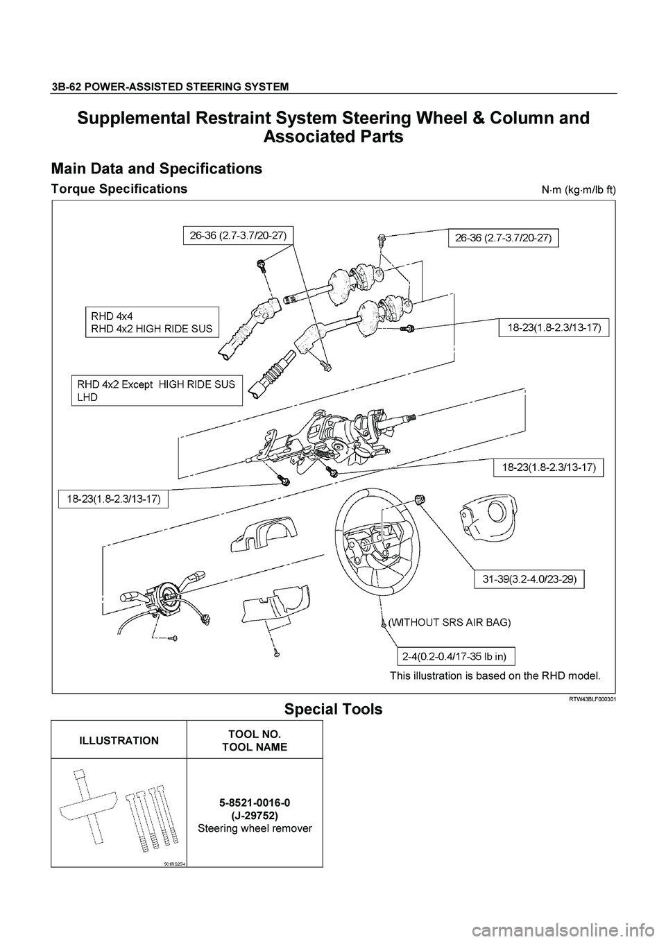
3B-62 POWER-ASSISTED STEERING SYSTEM
Supplemental Restraint System Steering Wheel & Column and
Associated Parts
Main Data and Specifications
Torque Specifications N�
m (kg�
m/lb ft)
This illustration is based on the RHD model.
RTW43BLF000301
Special Tools
ILLUSTRATION
TOOL NO.
TOOL NAME
5-8521-0016-0
(J-29752)
Steering wheel remover