Page 3503 of 4264
, then tighten it to the specified
torque.
Torque: 55N
�
�� �m (5.6kg
�
�� �m/41lb ft)
3.")
FRONT SUSPENSION 3C-11
NOTE: Paint mark to be outer side of after assembly to
vehicle.
2. Install nut (2), then tighten it to the specified
torque.
Torque: 55N
�
�� �m (5.6kg
�
�� �m/41lb ft)
3. Install bolt (7) and nut (4), then tighten to the
specified torque.
Buffer clearance: 25.9 mm (1.02 in)
Torque: 137N�
�� �m (14.0kg�
�� �m/101 lb ft)
NOTE: Apply oil to the thread.
NOTE: Tighten the bolt and nut with the parts in the
position shown in the illustration below.
RTW340SH001301-X
4. Install nut (6), then tighten it to the specified
torque.
Torque: 50N�
�� �m (5.1kg�
�� �m/37 lb ft)
5. Tighten the cam bolt (8) and nut (3), it to the
interim torque, then turn the cam bolt to the setting
mark applied during disassembly.
6. Install ball joint nut, then tighten it to the specified
torque with just enough additional torque to align
cotter pin holes. Install new cotter pin (5).
Torque: 147N�
�� �m (15.0kg�
�� �m/108 lb ft)
NOTE: Check the trim height. Refer to Front Alignment
Inspection and Adjustment.
7. Nut (3) tighten it to the specified torque.
Buffer clearance: 25.9 mm (1.02 in)
Torque: 186N�
�� �m (19.0kg�
�� �m/137 lb ft)
NOTE: Apply oil to the thread.
NOTE: Tighten the bolt and nut with the parts in the
position shown in the illustration below.
RTW340SH001301-X
8. Install wheel and tire assembly. Refer to wheel in
this section.
Page 3510 of 4264

3C-18 FRONT SUSPENSION
6. Remove the stabilizer link nut. Right and left.
7. Remove the wheel speed sensor from the knuckle.
8. Remove back plate.
9. Remove lower ball joint by using remover 5-8840- 2017-0.
CAUTION: Be careful not to damage the ball joint
boot.
P1010009
10. Remove upper ball joint by using remover 5-8840-
2017-0.
CAUTION: Be careful not to damage the ball joint
boot.
P1010011
11. Remove knuckle.
Inspection and Repair
Make necessary correction or parts replacement if
wear, damage, corrosion or any other abnormal
condition are found through inspection.
Check the following parts:
�
Knuckle
�
Knuckle arm
Installation
1. Install knuckle assembly.
2. Install upper ball joint and tighten the nut to the
specified torque, with just enough additional torque
to align cotter pin holes. Install new cotter pin (1).
Torque: 98 N �
��
�
m (10.0kg �
��
�
m/72 lb ft)
3. Install lower ball joint and tighten the nut to the specified torque, with just enough additional torque
to align cotter pin holes. Install new cotter pin (4).
Torque: 147N �
��
�
m (15.0kg �
��
�
m/108 lb ft)
4. Install back plate.
5. Install wheel speed sensor.
6. Install stabilizer link nut. Right and left.
Page 3523 of 4264

Nut
(2)
Rubber Bushing and Washer
(3) Bolt and Nut
(4)
Shock Absorber
(5")
FRONT SUSPENSION 3C-31
Shock Absorber
Shock Absorber and Associated Parts
RTW340MF000901
Legend
(1)
Nut
(2)
Rubber Bushing and Washer
(3) Bolt and Nut
(4)
Shock Absorber
(5) Rubber Bushing and Washer
Removal
1. Raise the vehicle and support it with suitable
safety stands.
2. Remove wheel and tire assembly. Refer to Wheel
Replacement in this section.
3. Remove bolt and nut.
4. Remove nut.
5. Remove rubber bushing and washer.
6. Remove shock absorber.
7. Remove rubber bushing and washer.
Inspection and Repair
Make necessary correction or parts replacement if
wear, damage, corrosion or any other abnormal
condition are found through inspection.
Check the following parts :
�
Shock absorber
�
Rubber bushing
Installation
1. Install rubber bushing and washer.
2. Install shock absorber.
3. Install rubber bushing and washer.
4. Install nut (1), then tighten it to the specified
torque.
Torque: 20 N�
�� �m (2.0kg�
�� �m/14 lb ft)
5. Install bolt and nut (3), then tighten to the specified
torque.
Torque: 93 N�
�� �m (9.5kg�
�� �m/69 lb ft)
Page 3573 of 4264

WHEELS AND TIRES 3E-1
SECTION 3E
WHEELS AND TIRES
TABLE OF CONTENTS
PAGE
Main Data and Specifications ........................................................................................... 3E- 2
Torque Specifications ....................................................................................................... 3E- 3
Special Parts Fixing Nuts and Bolts ............................................................................ 3E- 3
Wheels and Tires ...............................................................................................................3E- 4
General Description ...................................................................................................... 3E- 4
Servicing ........................................................................................................................ 3E- 6
Disassembly and Reassembly ..................................................................................... 3E- 7
Inspection and Repair................................................................................................... 3E- 8
Troubleshooting ................................................................................................................3E- 10
Page 3575 of 4264
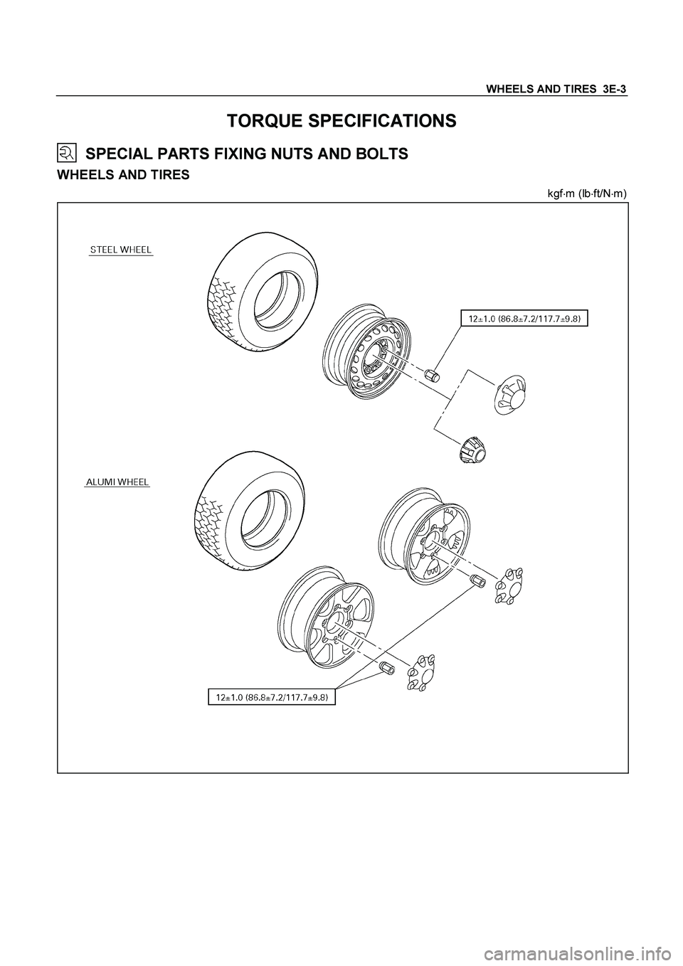
WHEELS AND TIRES 3E-3
TORQUE SPECIFICATIONS
SPECIAL PARTS FIXING NUTS AND BOLTS
WHEELS AND TIRES
kgf�
m (lb�
ft/N�
m)
Page 3578 of 4264
3E-6 WHEELS AND TIRES
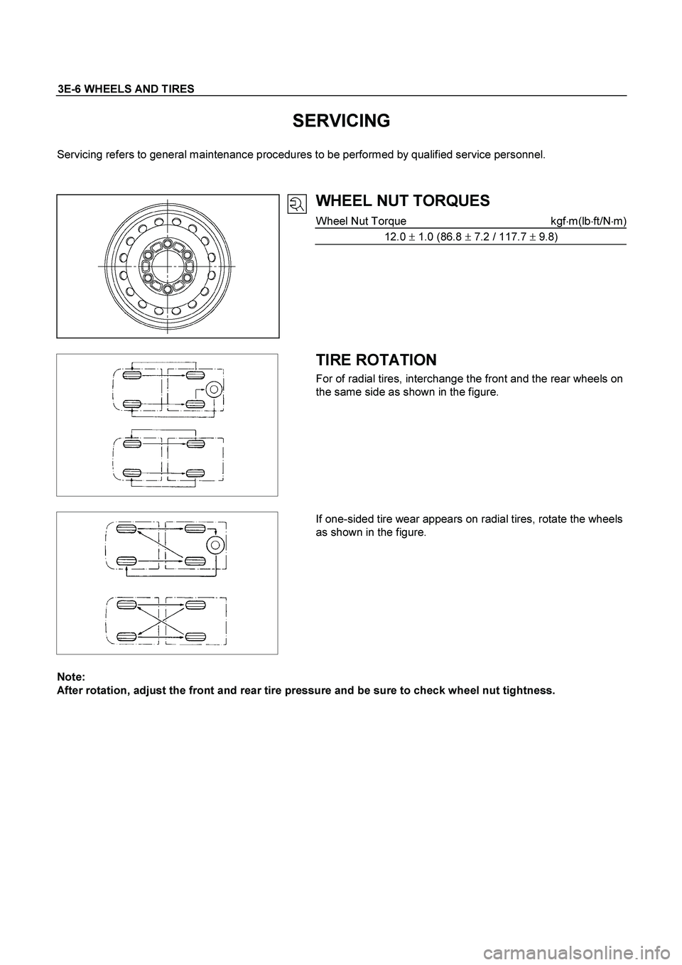
SERVICING
Servicing refers to general maintenance procedures to be performed by qualified service personnel.
WHEEL NUT TORQUES
Wheel Nut Torque kgf�m(lb�ft/N�m)
12.0 � 1.0 (86.8 � 7.2 / 117.7 � 9.8)
TIRE ROTATION
For of radial tires, interchange the front and the rear wheels on
the same side as shown in the figure.
If one-sided tire wear appears on radial tires, rotate the wheels
as shown in the figure.
Note:
After rotation, adjust the front and rear tire pressure and be sure to check wheel nut tightness.
Page 3581 of 4264
WHEELS AND TIRES 3E-9
Important Operations
1. Tire Assembly
Align the match mark (approx. 10mm diameter paint mark) of
wheel with match mark (approx. 8mm diameter red paint mark)
of tire to assemble. If the match mark at wheel has
disappeared, align with air valve to assemble.
2. Wheel and Tire Assembly
3. Wheel Nut
Tighten wheel nuts in numerical order.
Wheel Nut Torque kgf�m (lb�ft/N�m)
12.0 � 1.0 (86.8 � 7.2 / 117.7 � 9.8)
Page 3621 of 4264
TRANSFER CASE 7D-33
Main Data and Specifications
General Specifications
Type Synchronized type gears shifting between the 2 and 4 wheel drive mode.
Planetary type gears shifting between “low" and “high".
Control method Remote control with the button switch on the instrument panel for gears
shifting among “2H" , “4H" and “4L".
Gear ratio High; 1.000
Low; 2.482
Oil capacity 1.3 lit. (1.37 U.S. quart)
Type of lubricant BESCO GEAR OIL TRANSAXLE (5W-30)
Refer to chart in Section 0
Torque Specifications
N�m (kg�m/lb ft)
RTW47DLF000201
 of
wheel with match mark (approx. 8mm diameter red paint mark)
of tire to a")
