Page 1120 of 3371
COMBINATION METERS
DI-17
C
D
E
F
G
H
I
J
L
MA
B
DI
Revision: August 20072004 QX56
How to Proceed With Trouble DiagnosisEKS007DS
1. Confirm the symptom or customer complaint.
2. Perform diagnosis according to diagnosis flow. Refer to DI-17, "
Diagnosis Flow" .
3. According to the symptom chart, repair or replace the cause of the symptom.
4. Does the meter operate normally? If so, go to 5. If not, go to 2.
5. Inspection End.
Diagnosis FlowEKS007DT
1. CHECK WARNING INDICATOR ILLUMINATION
1. Turn ignition switch ON.
2. Make sure warning indicators (such as malfunction indicator lamp and oil pressure low/coolant tempera-
ture high warning indicator) illuminate.
Do warning indicators illuminate?
YES >> GO TO 2.
NO >> Check ignition power supply system of combination meter. Refer to DI-18, "
Power Supply and
Ground Circuit Inspection" .
2. CHECK SELF-DIAGNOSIS OPERATION OF COMBINATION METER
Perform combination meter self-diagnosis. Refer to DI-13, "
SELF-DIAGNOSIS FUNCTION" .
Does self-diagnosis function operate?
YES >> GO TO 3.
NO >> Check the following.
�Combination meter power supply and ground circuit. Refer to DI-18, "Power Supply and
Ground Circuit Inspection" .
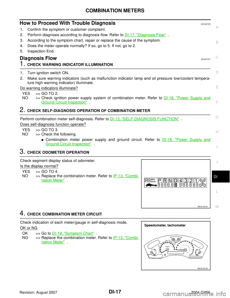
3. CHECK ODOMETER OPERATION
Check segment display status of odometer.
Is the display normal?
YES >> GO TO 4.
NO >> Replace the combination meter. Refer to IP-13, "
Combi-
nation Meter" .
4. CHECK COMBINATION METER CIRCUIT
Check indication of each meter/gauge in self-diagnosis mode.
OK or NG
OK >> Go to DI-19, "Symptom Chart" .
NG >> Replace the combination meter. Refer to IP-13, "
Combi-
nation Meter" .
WKIA1531E
WKIA1814E
Page 1122 of 3371
COMBINATION METERS
DI-19
C
D
E
F
G
H
I
J
L
MA
B
DI
Revision: August 20072004 QX56
Symptom ChartEKS007DV
Vehicle Speed Signal InspectionEKS007DW
1. CHECK ABS ACTUATOR AND ELECTRIC UNIT (CONTROL UNIT) SELF-DIAGNOSIS
Refer to BRC-29, "
SELF-DIAGNOSIS" .
OK or NG
OK >> Replace the combination meter. Refer to IP-13, "Combination Meter" .
NG >> Perform the "Diagnostic Procedure" for displayed DTC. Refer to BRC-11, "
TROUBLE DIAGNO-
SIS" .
Engine Oil Pressure Signal Inspection EKS0086D
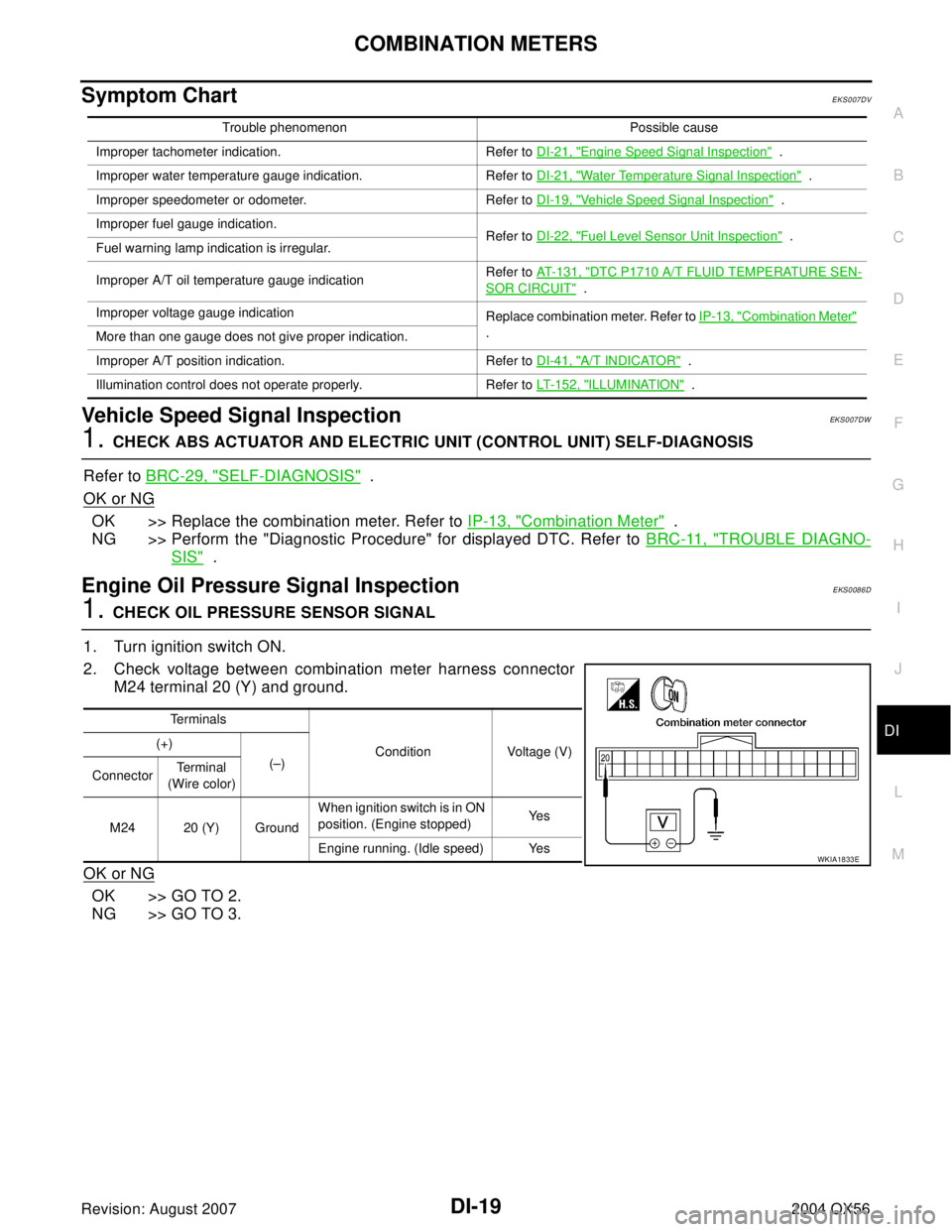
1. CHECK OIL PRESSURE SENSOR SIGNAL
1. Turn ignition switch ON.
2. Check voltage between combination meter harness connector
M24 terminal 20 (Y) and ground.
OK or NG
OK >> GO TO 2.
NG >> GO TO 3.
Trouble phenomenon Possible cause
Improper tachometer indication. Refer to DI-21, "
Engine Speed Signal Inspection" .
Improper water temperature gauge indication. Refer to DI-21, "
Water Temperature Signal Inspection" .
Improper speedometer or odometer. Refer to DI-19, "
Vehicle Speed Signal Inspection" .
Improper fuel gauge indication.
Refer to DI-22, "
Fuel Level Sensor Unit Inspection" .
Fuel warning lamp indication is irregular.
Improper A/T oil temperature gauge indicationRefer to AT-131, "
DTC P1710 A/T FLUID TEMPERATURE SEN-
SOR CIRCUIT" .
Improper voltage gauge indication
Replace combination meter. Refer to IP-13, "
Combination Meter"
.
More than one gauge does not give proper indication.
Improper A/T position indication. Refer to DI-41, "
A/T INDICATOR" .
Illumination control does not operate properly. Refer to LT-152, "
ILLUMINATION" .
Te r m i n a l s
Condition Voltage (V) (+)
(–)
ConnectorTe r m i n a l
(Wire color)
M24 20 (Y) GroundWhen ignition switch is in ON
position. (Engine stopped)Ye s
Engine running. (Idle speed) Yes
WKIA1833E
Page 1123 of 3371
DI-20
COMBINATION METERS
Revision: August 20072004 QX56
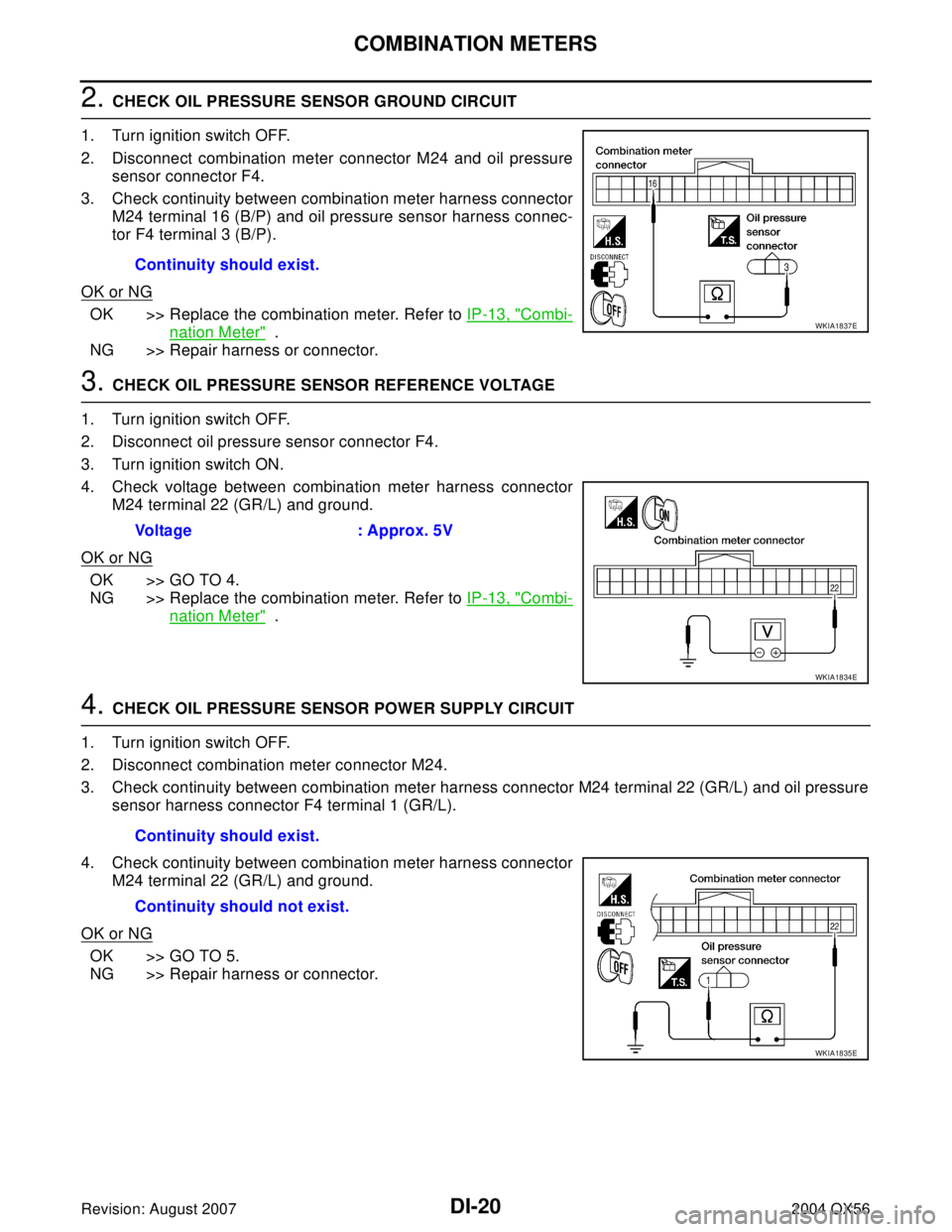
2. CHECK OIL PRESSURE SENSOR GROUND CIRCUIT
1. Turn ignition switch OFF.
2. Disconnect combination meter connector M24 and oil pressure
sensor connector F4.
3. Check continuity between combination meter harness connector
M24 terminal 16 (B/P) and oil pressure sensor harness connec-
tor F4 terminal 3 (B/P).
OK or NG
OK >> Replace the combination meter. Refer to IP-13, "Combi-
nation Meter" .
NG >> Repair harness or connector.
3. CHECK OIL PRESSURE SENSOR REFERENCE VOLTAGE
1. Turn ignition switch OFF.
2. Disconnect oil pressure sensor connector F4.
3. Turn ignition switch ON.
4. Check voltage between combination meter harness connector
M24 terminal 22 (GR/L) and ground.
OK or NG
OK >> GO TO 4.
NG >> Replace the combination meter. Refer to IP-13, "
Combi-
nation Meter" .
4. CHECK OIL PRESSURE SENSOR POWER SUPPLY CIRCUIT
1. Turn ignition switch OFF.
2. Disconnect combination meter connector M24.
3. Check continuity between combination meter harness connector M24 terminal 22 (GR/L) and oil pressure
sensor harness connector F4 terminal 1 (GR/L).
4. Check continuity between combination meter harness connector
M24 terminal 22 (GR/L) and ground.
OK or NG
OK >> GO TO 5.
NG >> Repair harness or connector.Continuity should exist.
WKIA1837E
Voltage : Approx. 5V
WKIA1834E
Continuity should exist.
Continuity should not exist.
WKIA1835E
Page 1124 of 3371
COMBINATION METERS
DI-21
C
D
E
F
G
H
I
J
L
MA
B
DI
Revision: August 20072004 QX56
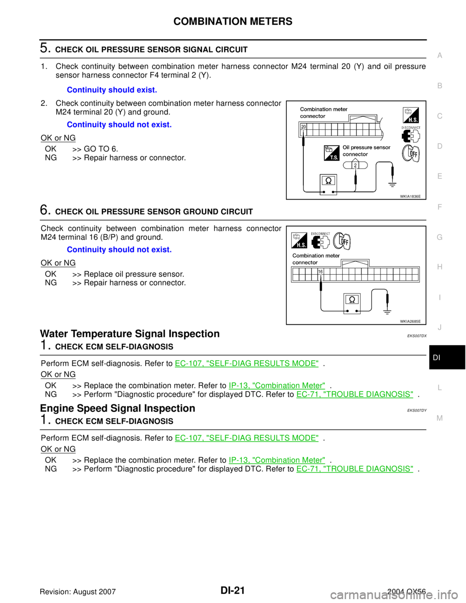
5. CHECK OIL PRESSURE SENSOR SIGNAL CIRCUIT
1. Check continuity between combination meter harness connector M24 terminal 20 (Y) and oil pressure
sensor harness connector F4 terminal 2 (Y).
2. Check continuity between combination meter harness connector
M24 terminal 20 (Y) and ground.
OK or NG
OK >> GO TO 6.
NG >> Repair harness or connector.
6. CHECK OIL PRESSURE SENSOR GROUND CIRCUIT
Check continuity between combination meter harness connector
M24 terminal 16 (B/P) and ground.
OK or NG
OK >> Replace oil pressure sensor.
NG >> Repair harness or connector.
Water Temperature Signal Inspection EKS007DX
1. CHECK ECM SELF-DIAGNOSIS
Perform ECM self-diagnosis. Refer to EC-107, "
SELF-DIAG RESULTS MODE" .
OK or NG
OK >> Replace the combination meter. Refer to IP-13, "Combination Meter" .
NG >> Perform "Diagnostic procedure" for displayed DTC. Refer to EC-71, "
TROUBLE DIAGNOSIS" .
Engine Speed Signal Inspection EKS007DY
1. CHECK ECM SELF-DIAGNOSIS
Perform ECM self-diagnosis. Refer to EC-107, "
SELF-DIAG RESULTS MODE" .
OK or NG
OK >> Replace the combination meter. Refer to IP-13, "Combination Meter" .
NG >> Perform "Diagnostic procedure" for displayed DTC. Refer to EC-71, "
TROUBLE DIAGNOSIS" . Continuity should exist.
Continuity should not exist.
WKIA1836E
Continuity should not exist.
WKIA2685E
Page 1141 of 3371
DI-38
WARNING LAMPS
Revision: August 20072004 QX56
Oil Pressure Warning Lamp Stays Off (Ignition Switch ON)EKS007EA
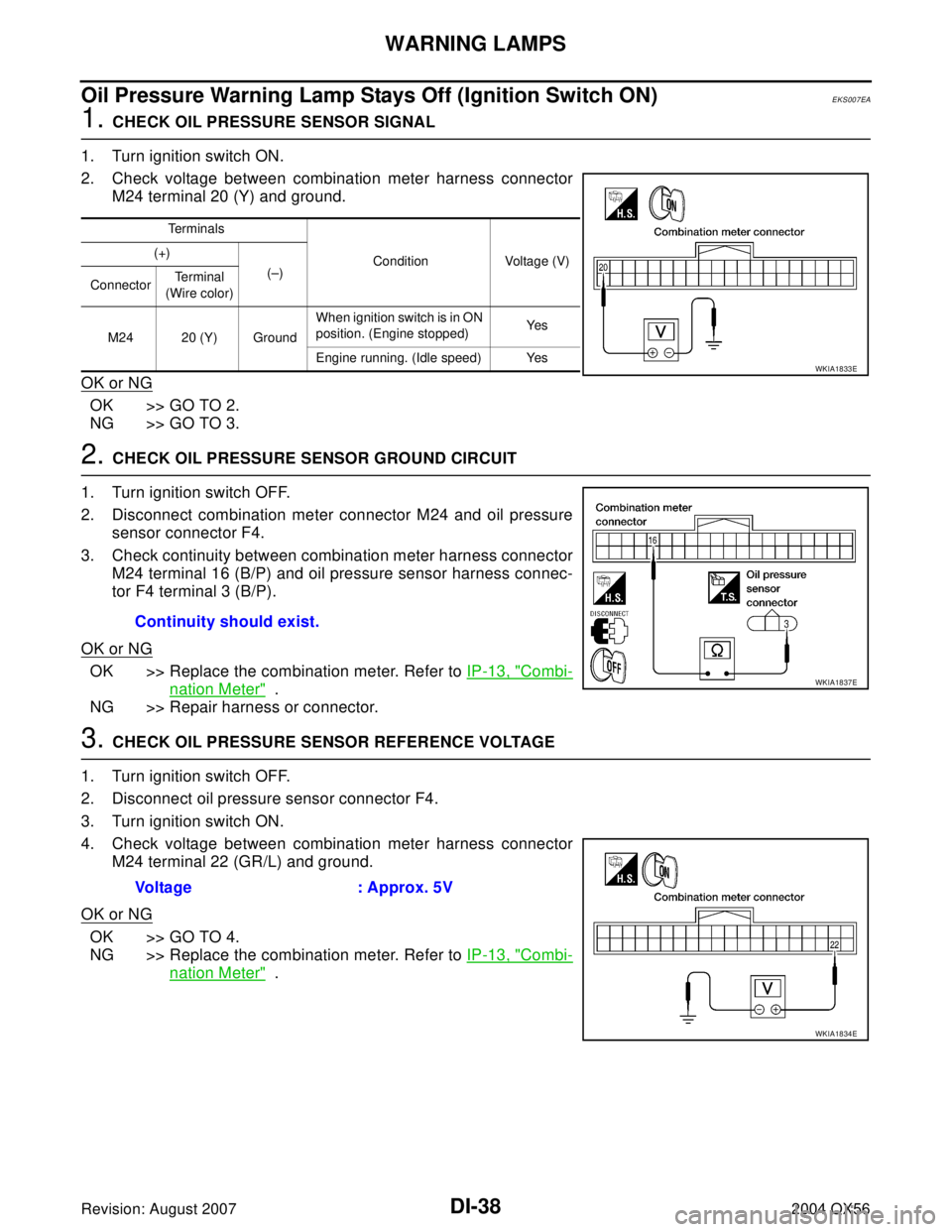
1. CHECK OIL PRESSURE SENSOR SIGNAL
1. Turn ignition switch ON.
2. Check voltage between combination meter harness connector
M24 terminal 20 (Y) and ground.
OK or NG
OK >> GO TO 2.
NG >> GO TO 3.
2. CHECK OIL PRESSURE SENSOR GROUND CIRCUIT
1. Turn ignition switch OFF.
2. Disconnect combination meter connector M24 and oil pressure
sensor connector F4.
3. Check continuity between combination meter harness connector
M24 terminal 16 (B/P) and oil pressure sensor harness connec-
tor F4 terminal 3 (B/P).
OK or NG
OK >> Replace the combination meter. Refer to IP-13, "Combi-
nation Meter" .
NG >> Repair harness or connector.
3. CHECK OIL PRESSURE SENSOR REFERENCE VOLTAGE
1. Turn ignition switch OFF.
2. Disconnect oil pressure sensor connector F4.
3. Turn ignition switch ON.
4. Check voltage between combination meter harness connector
M24 terminal 22 (GR/L) and ground.
OK or NG
OK >> GO TO 4.
NG >> Replace the combination meter. Refer to IP-13, "
Combi-
nation Meter" .
Terminals
Condition Voltage (V) (+)
(–)
ConnectorTe r m i n a l
(Wire color)
M24 20 (Y) GroundWhen ignition switch is in ON
position. (Engine stopped)Ye s
Engine running. (Idle speed) Yes
WKIA1833E
Continuity should exist.
WKIA1837E
Voltage : Approx. 5V
WKIA1834E
Page 1142 of 3371
WARNING LAMPS
DI-39
C
D
E
F
G
H
I
J
L
MA
B
DI
Revision: August 20072004 QX56
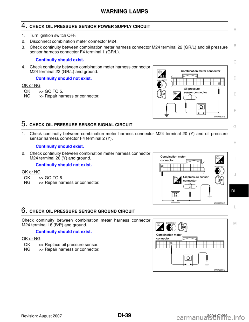
4. CHECK OIL PRESSURE SENSOR POWER SUPPLY CIRCUIT
1. Turn ignition switch OFF.
2. Disconnect combination meter connector M24.
3. Check continuity between combination meter harness connector M24 terminal 22 (GR/L) and oil pressure
sensor harness connector F4 terminal 1 (GR/L).
4. Check continuity between combination meter harness connector
M24 terminal 22 (GR/L) and ground.
OK or NG
OK >> GO TO 5.
NG >> Repair harness or connector.
5. CHECK OIL PRESSURE SENSOR SIGNAL CIRCUIT
1. Check continuity between combination meter harness connector M24 terminal 20 (Y) and oil pressure
sensor harness connector F4 terminal 2 (Y).
2. Check continuity between combination meter harness connector
M24 terminal 20 (Y) and ground.
OK or NG
OK >> GO TO 6.
NG >> Repair harness or connector.
6. CHECK OIL PRESSURE SENSOR GROUND CIRCUIT
Check continuity between combination meter harness connector
M24 terminal 16 (B/P) and ground.
OK or NG
OK >> Replace oil pressure sensor.
NG >> Repair harness or connector.Continuity should exist.
Continuity should not exist.
WKIA1835E
Continuity should exist.
Continuity should not exist.
WKIA1836E
Continuity should not exist.
WKIA2685E
Page 1143 of 3371
DI-40
WARNING LAMPS
Revision: August 20072004 QX56
Oil Pressure Warning Lamp Does Not Turn Off (Oil Pressure Is Normal)EKS007EB
NOTE:
For oil pressure inspection, refer to LU-7, "
OIL PRESSURE CHECK" .
1. CHECK ENGINE OIL PRESSURE GAUGE OPERATION
Observe operation of engine oil pressure gauge.
Does engine oil pressure gauge function properly?
YES >> Replace the combination meter. Refer to DI-25, "Removal and Installation of Combination Meter"
.
NO >> Go to DI-19, "
Engine Oil Pressure Signal Inspection" .
Page 1224 of 3371
BASIC SERVICE PROCEDURE
EC-33
C
D
E
F
G
H
I
J
K
L
MA
EC
Revision: August 20072004 QX56
3. Check ignition timing.
Idle Speed/Ignition Timing/Idle Mixture Ratio AdjustmentUBS00GZL
PREPARATION
1. Make sure that the following parts are in good order.
�Battery
�Ignition system
�Engine oil and coolant levels
�Fuses
�ECM harness connector
�Vacuum hoses
�Air intake system
(Oil filler cap, oil level gauge, etc.)
�Fuel pressure
�Engine compression
�Throttle valve
�Evaporative emission system
2. On air conditioner equipped models, checks should be carried out while the air conditioner is OFF.
3. On automatic transmission equipped models, when checking idle rpm, ignition timing and mixture ratio,
checks should be carried out while shift lever is in N position.
4. When measuring CO percentage, insert probe more than 40 cm (15.7 in) into tail pipe.
5. Turn off headlamp, heater blower, rear window defogger.
6. Keep front wheels pointed straight ahead.
SEF 0 11V
BBIA0379E