Page 3140 of 3371

ALL-MODE 4WD SYSTEM
TF-15
C
E
F
G
H
I
J
K
L
MA
B
TF
Revision: August 20072004 QX56
Description of Electrical PartsEDS0017R
TRANSFER MOTOR
1. The transfer motor drives the sub-oil pump to provide proper lubrication and oil pressure control when the
vehicle is at standstill, during low-speed operations or is being driven in reverse.
2. The main oil pump is operated by the driving force of the mainshaft. In other words, sufficient oil pressure
buildup does not occur when the vehicle is at standstill or during low-speed operations. While the vehicle
is being driven in reverse, the main oil pump rotates in the reverse direction. Therefore the main oil pump
does not discharge oil pressure. During any of the above vehicle operations, the transfer motor drives the
sub-oil pump to compensate for insufficient oil pressure.
3. The transfer motor operates as follows:
1. The motor relay turns OFF in the 2WD mode.
2. The motor relay operates as described in the table below in modes other than the 2WD mode.
Ta b l e 1
Ta b l e 2
NOTE:
OFF (after 2.5 seconds have elapsed.)
4. 4WD shift switch, PNP switch, Neutral-4LO switch, vehicle speed sensor and throttle position sensor are
used in conjunction with the transfer motor.
WAIT DETECTION SWITCH
1. The wait detection switch releases the “booming” torque produced in the propeller shaft. After the release
of the “booming” torque, the wait detection switch helps provide the 4WD lock gear (clutch drum) shifts. A
difference may occur between the operation (“4LO” to “4H” shift only) of the 4WD shift switch and actual
drive mode. At this point, the wait detection switch senses an actual drive mode.
2. The wait detection switch operates as follows:
4WD lock gear (clutch drum) locked: ON
4WD lock gear (clutch drum) released: OFF
3. The wait detection switch senses an actual drive mode and the 4WD shift indicator lamp indicates the
vehicle drive mode.
2-4WD SHIFT SOLENOID VALVE
The 2-4WD shift solenoid valve operates to apply oil pressure to the wet, multiplate clutch, depending on the
drive mode. The driving force is transmitted to the front wheels through the clutch when the vehicle is set in the
4WD mode. Setting the vehicle in the 2WD mode requires no pressure buildup. In other words, pressure force
applied to the wet, multiplate clutch becomes zero.
PNP switch “R” position VFF (Vehicle speed) A/T position Motor relay drive command
ON — R ON
OFF0Positions other than the “P” or
“N” positionsON
—“P” or “N” position (See Table
2.)—
0 < VFF ≤ 50 km/h (31 MPH) — ON
50 km/h (31 MPH) < VFF < 55
km/h (34 MPH)—HOLD
55 km/h (34 MPH) ≤ VFF — OFF
A/T position N-4L SW 4WD modeThrottle position
0 - 0.07/8 0.07/8 - 1/8 1/8 - MAX
NOFFLOCK (4H) ON ON ON
Positions other than
the LOCK position
(2WD or AUTO)See NOTE. HOLD ON
ON — See NOTE. HOLD ON
P——See NOTE.HOLDON
Page 3141 of 3371
TF-16
ALL-MODE 4WD SYSTEM
Revision: August 20072004 QX56
LINE PRESSURE SWITCH
1. With the transfer system design, control of the oil pressure provides the transmission of drive torque to the
front wheels. The main pressure to control the oil pressure is referred to as the line pressure.
The line pressure switch determines whether or not adequate line pressure has built up under different
operating conditions.
2. The line pressure switch turns ON when line pressure is produced.
3. The line pressure switch senses line pressure abnormalities and turns the 4WD warning lamp ON.
Page 3219 of 3371

TF-94
TROUBLE DIAGNOSES FOR SYMPTOMS
Revision: August 20072004 QX56
Symptom 9. 4WD System Does Not Operate (The Vehicle Cannot Be Put Into
4WD Mode-Hydraulic System Failure)
EDS0018M
1. CHECK INPUT SIGNAL
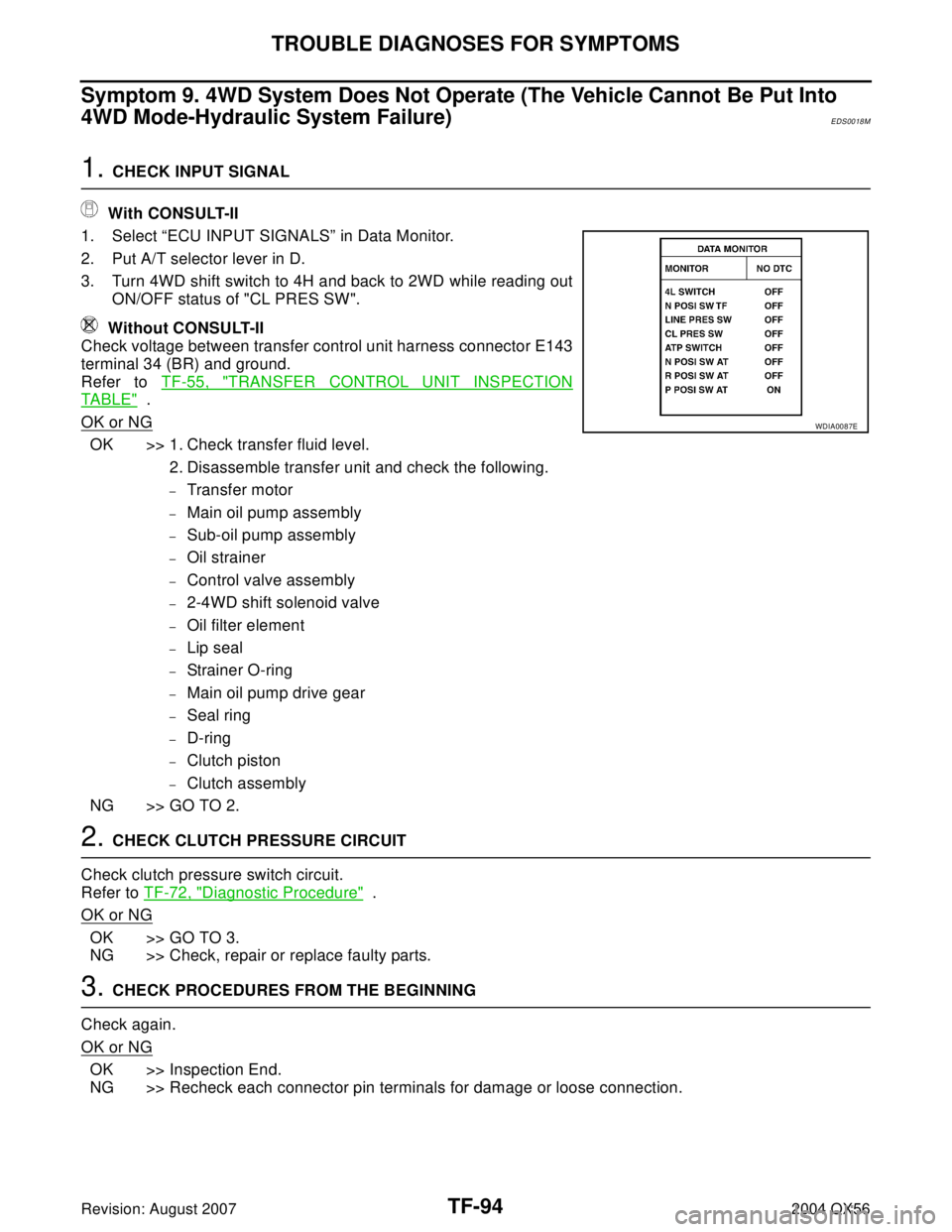
With CONSULT-II
1. Select “ECU INPUT SIGNALS” in Data Monitor.
2. Put A/T selector lever in D.
3. Turn 4WD shift switch to 4H and back to 2WD while reading out
ON/OFF status of "CL PRES SW".
Without CONSULT-II
Check voltage between transfer control unit harness connector E143
terminal 34 (BR) and ground.
Refer to TF-55, "
TRANSFER CONTROL UNIT INSPECTION
TABLE" .
OK or NG
OK >> 1. Check transfer fluid level.
2. Disassemble transfer unit and check the following.
–Transfer motor
–Main oil pump assembly
–Sub-oil pump assembly
–Oil strainer
–Control valve assembly
–2-4WD shift solenoid valve
–Oil filter element
–Lip seal
–Strainer O-ring
–Main oil pump drive gear
–Seal ring
–D-ring
–Clutch piston
–Clutch assembly
NG >> GO TO 2.
2. CHECK CLUTCH PRESSURE CIRCUIT
Check clutch pressure switch circuit.
Refer to TF-72, "
Diagnostic Procedure" .
OK or NG
OK >> GO TO 3.
NG >> Check, repair or replace faulty parts.
3. CHECK PROCEDURES FROM THE BEGINNING
Check again.
OK or NG
OK >> Inspection End.
NG >> Recheck each connector pin terminals for damage or loose connection.
WDIA0087E
Page 3236 of 3371
OVERHAUL
TF-111
C
E
F
G
H
I
J
K
L
MA
B
TF
Revision: August 20072004 QX56
46. Snap ring 47. Retaining pin 48. L-H fork
49. 2-4 fork 50. Shift fork spring 51. Fork guide
52. Retainer pin 53. Shift rod
1. Dust cover 2. Oil seal 3. Rear case
4. Air breather 5. Seal ring 6. Main oil pump cover
7. Inner gear 8. Outer gear 9. Main oil pump housing
10. D-ring 11. D-ring 12. Clutch piston
13. Thrust needle bearing race 14. Oil strainer 15. O-ring
16. Snap ring 17. Control valve assembly 18. Lip seal (7 pieces)
19. Washer 20. Filler plug 21. Filler stud
22. O-ring 23. Oil filter 24. ATP switch
25 Neutral-4LO switch 26. Oil pressure check plug 27. Harness bracket
28. Stem bleeder 29. Harness bracket 30. Center case
31. Mainshaft rear bearing 32. C-ring 33. Washer holder
34. Snap ring 35. Sub oil pump housing 36. Outer gear
37. Inner gear 38. Sub oil pump cover 39. O-ring
40. Transfer motor 41. Connector bracket
SDIA2091E
Page 3243 of 3371
TF-118
CENTER CASE
Revision: August 20072004 QX56
10. Tap mainshaft, using suitable tool to remove it from clutch drum
and clutch hub.
11. Remove needle bearing and spacer from the mainshaft.
12. Remove the snap ring from the clutch hub.
CLUTCH PISTON
1. Remove oil pressure check plug from oil pressure check port.
2. Apply air gradually from oil pressure check port, and remove
clutch piston from center case.
SMT914C
WDIA0101E
SDIA2 115 E
SDIA2 116 E
Page 3270 of 3371

CENTER CASE
TF-145
C
E
F
G
H
I
J
K
L
MA
B
TF
Revision: August 20072004 QX56
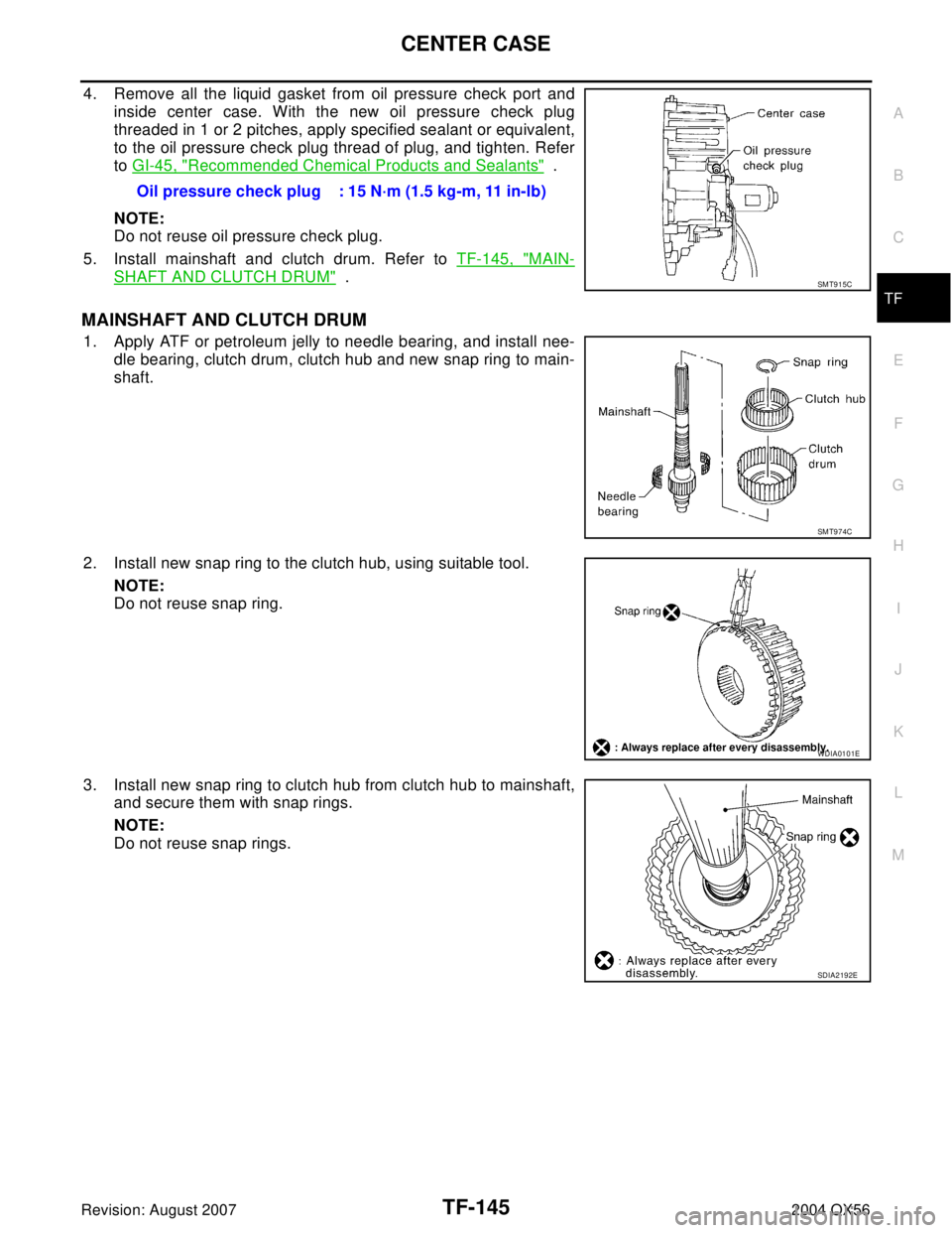
4. Remove all the liquid gasket from oil pressure check port and
inside center case. With the new oil pressure check plug
threaded in 1 or 2 pitches, apply specified sealant or equivalent,
to the oil pressure check plug thread of plug, and tighten. Refer
to GI-45, "
Recommended Chemical Products and Sealants" .
NOTE:
Do not reuse oil pressure check plug.
5. Install mainshaft and clutch drum. Refer to TF-145, "
MAIN-
SHAFT AND CLUTCH DRUM" .
MAINSHAFT AND CLUTCH DRUM
1. Apply ATF or petroleum jelly to needle bearing, and install nee-
dle bearing, clutch drum, clutch hub and new snap ring to main-
shaft.
2. Install new snap ring to the clutch hub, using suitable tool.
NOTE:
Do not reuse snap ring.
3. Install new snap ring to clutch hub from clutch hub to mainshaft,
and secure them with snap rings.
NOTE:
Do not reuse snap rings.Oil pressure check plug : 15 N·m (1.5 kg-m, 11 in-lb)
SMT915C
SMT974C
WDIA0101E
SDIA2192E