Page 3171 of 3371
TF-46
TROUBLE DIAGNOSIS — INTRODUCTION
Revision: August 20072004 QX56
Work FlowEDS0017X
HOW TO PERFORM TROUBLE DIAGNOSES FOR QUICK AND ACCURATE REPAIR
A good understanding of the malfunction conditions can make troubleshooting faster and more accurate.
In general, each customer feels differently about a problem. It is important to fully understand the symptoms or
conditions for a customer complaint.
Make good use of the two sheets provided, “Information from Customer” (Refer to TF-44
) and “Diagnostic
Worksheet” (Refer to TF-44
), to perform the best troubleshooting possible.
*1:TF-47*2:TF-47*3:TF-47
*4:TF-85 - TF-94*5:TF-60 - TF-82*6:TF-47
WDIA0102E
Page 3209 of 3371

TF-84
SHIFT ACTUATOR CIRCUIT
Revision: August 20072004 QX56
6. CHECK INPUT SIGNAL
Without CONSULT-II
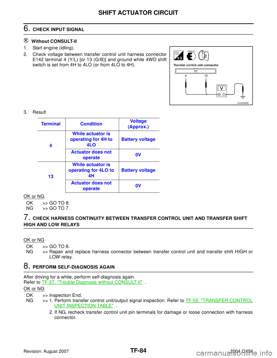
1. Start engine (idling).
2. Check voltage between transfer control unit harness connector
E142 terminal 4 (Y/L) [or 13 (G/B)] and ground while 4WD shift
switch is set from 4H to 4LO (or from 4LO to 4H).
3. Result
OK or NG
OK >> GO TO 8.
NG >> GO TO 7.
7. CHECK HARNESS CONTINUITY BETWEEN TRANSFER CONTROL UNIT AND TRANSFER SHIFT
HIGH AND LOW RELAYS
OK or NG
OK >> GO TO 8.
NG >> Repair and replace harness connector between transfer control unit and transfer shift HIGH or
LOW relay.
8. PERFORM SELF-DIAGNOSIS AGAIN
After driving for a while, perform self-diagnosis again.
Refer to TF-27, "
Trouble Diagnosis without CONSULT-II" .
OK or NG
OK >> Inspection End.
NG >> 1. Perform transfer control unit/output signal inspection. Refer to TF-55, "
TRANSFER CONTROL
UNIT INSPECTION TABLE" .
2. If NG, recheck transfer control unit pin terminals for damage or loose connection with harness
connector.
LDIA0083E
Terminal ConditionVo l ta g e
(Approx.)
4While actuator is
operating for 4H to
4LOBattery voltage
Actuator does not
operate0V
13While actuator is
operating for 4LO to
4HBattery voltage
Actuator does not
operate0V
Page 3216 of 3371

TROUBLE DIAGNOSES FOR SYMPTOMS
TF-91
C
E
F
G
H
I
J
K
L
MA
B
TF
Revision: August 20072004 QX56
3. CHECK 4LO INDICATOR LAMP CIRCUIT AND COMBINATION METER
Check the following.
�Combination meter. Refer to DI-17, "How to Proceed With Trouble Diagnosis" .
�Continuity between ignition switch and combination meter
�Continuity between combination meter and transfer control unit
�Condition of ATP and neutral-4LO switch circuit. Refer to TF-69, "ATP SWITCH, WAIT DETECTION
SWITCH AND NEUTRAL-4LO SWITCH" .
OK or NG
OK >> Replace transfer control unit. Refer to TF-98, "Removal and Installation" .
NG >>
�Repair or replace harness or connector.
�Replace combination meter. Refer to DI-25, "Removal and Installation of Combination Meter" .
�Replace ATP or neutral-4LO switch.
Symptom 6. 4WD Shift Indicator Lamp Does Not Indicate “LOCK” (When 4WD
shift switch is set to “4H”, 4WD shift indicator lamp does not indicate “LOCK”)
EDS0018J
1. CHECK 4WD WARNING LAMP
Is 4WD warning lamp turned ON?
Ye s o r N o
Yes >> Refer to TF-27, "Trouble Diagnosis without CONSULT-
II" .
No >> GO TO 2.
2. CHECK NEUTRAL-4LO, WAIT DETECTION AND ATP SWITCH CIRCUITS
Check neutral-4LO, wait detection and ATP switch circuits. Refer to TF-69, "
ATP SWITCH, WAIT DETECTION
SWITCH AND NEUTRAL-4LO SWITCH" .
OK or NG
OK >> GO TO 3.
NG >> Check, repair or replace faulty parts.
3. CHECK PROCEDURES FROM THE BEGINNING AGAIN
Check again.
OK or NG
OK >> Inspection End.
NG >> Recheck each connector pin terminals for damage or loose connection.
WDIA0071E
Page 3287 of 3371
WT-8
LOW TIRE PRESSURE WARNING SYSTEM
Revision: August 20072004 QX56
BCM (BODY CONTROL MODULE)
Reads the air pressure signal received by the remote keyless entry
receiver, and controls the low tire pressure warning lamp and the
buzzer operations as shown below. It also has a judgement function
to detect a system malfunction.
LOW TIRE PRESSURE WARNING LAMP AND BUZZER
Indicates low tire pressure or system malfunction.
DISPLAY UNIT
Displays the air pressure of each tire.
�After the ignition switch is turned on, the pressure values are not
be displayed until the data of each wheel is received.
LEIA0068E
ConditionLow tire pressure
warning lampBuzzer
Less than 193 kPa (2.0 kg/cm
2 , 28 psi)
[Flat tire]ONSounds for
10 sec.
System malfunction ON OFF
LEIA0055E
WEIA0082E
Page 3297 of 3371
WT-18
TROUBLE DIAGNOSES
Revision: August 20072004 QX56
Data Monitor Mode
NOTE:
Before performing the self-diagnosis, be sure to register the ID, or the actual malfunction location may be different from that displayed on
CONSULT-II.MONITOR CONDITION SPECIFICATION
VHCL SPEED Drive vehicle. Vehicle speed (km/h or MPH)
AIR PRESS FL
AIR PRESS FR
AIR PRESS RR
AIR PRESS RL
�Drive vehicle for a few minutes.
Tire pressure (kPa or psi) or
�Ignition switch ON and activation tool
is transmitting activation signals.
ID REGST FL1
ID REGST FR1
ID REGST RR1
ID REGST RL1
Ignition switch ONRegistration ID: DONE
No registration ID: YET
WAR NIN G LAMPLow tire pressure warning lamp on: ON
Low tire pressure warning lamp off: OFF
BUZZERBuzzer in combination meter on: ON
Buzzer in combination meter off : OFF
Page 3326 of 3371

FRONT WIPER AND WASHER SYSTEM
WW-13
C
D
E
F
G
H
I
J
L
MA
B
WW
Revision: August 20072004 QX56
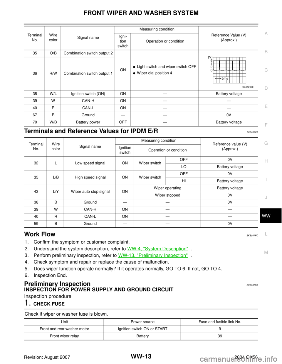
Terminals and Reference Values for IPDM E/R EKS007FB
Work FlowEKS007FC
1. Confirm the symptom or customer complaint.
2. Understand the system description, refer to WW-4, "
System Description" .
3. Perform preliminary inspection, refer to WW-13, "
Preliminary Inspection" .
4. Check symptom and repair or replace the cause of malfunction.
5. Does wiper function operate normally? If it operates normally, GO TO 6. If not, GO TO 4.
6. Inspection End.
Preliminary InspectionEKS007FD
INSPECTION FOR POWER SUPPLY AND GROUND CIRCUIT
Inspection procedure
1. CHECK FUSE
Check if wiper or washer fuse is blown.
35 O/B Combination switch output 2
ON
�Light switch and wiper switch OFF
�Wiper dial position 4
36 R/W Combination switch output 1
38 W/L Ignition switch (ON) ON — Battery voltage
39 W CAN-H ON — —
40 R CAN-L ON — —
67 B Ground — — 0V
70 W/B Battery power OFF — Battery voltage Te r m i n a l
No.Wire
colorSignal nameMeasuring condition
Reference Value (V)
(Approx.) Igni-
tion
switchOperation or condition
SKIA5292E
Te r m i n a l
No.Wire
colorSignal nameMeasuring condition
Reference value (V)
(Approx.) Ignition
switchOperation or condition
32 L Low speed signal ON Wiper switchOFF 0V
LO Battery voltage
35 L/B High speed signal ON Wiper switchOFF 0V
HI Battery voltage
43 L/Y Wiper auto stop signal ONWiper operating Battery voltage
Wiper stopped 0V
38 B Ground — — 0V
39 W CAN-H ON — —
40 R CAN-L ON — —
59 B Ground — — 0V
Unit Power source Fuse and fusible link No.
Front and rear washer motor Ignition switch ON or START 9
Front wiper relay Battery 39
Page 3327 of 3371

WW-14
FRONT WIPER AND WASHER SYSTEM
Revision: August 20072004 QX56
OK or NG
OK >> GO TO 2.
NG >> If fuse or fusible link is blown, be sure to eliminate cause of malfunction before installing new fuse
or fusible link. Refer to PG-4, "
POWER SUPPLY ROUTING CIRCUIT" .
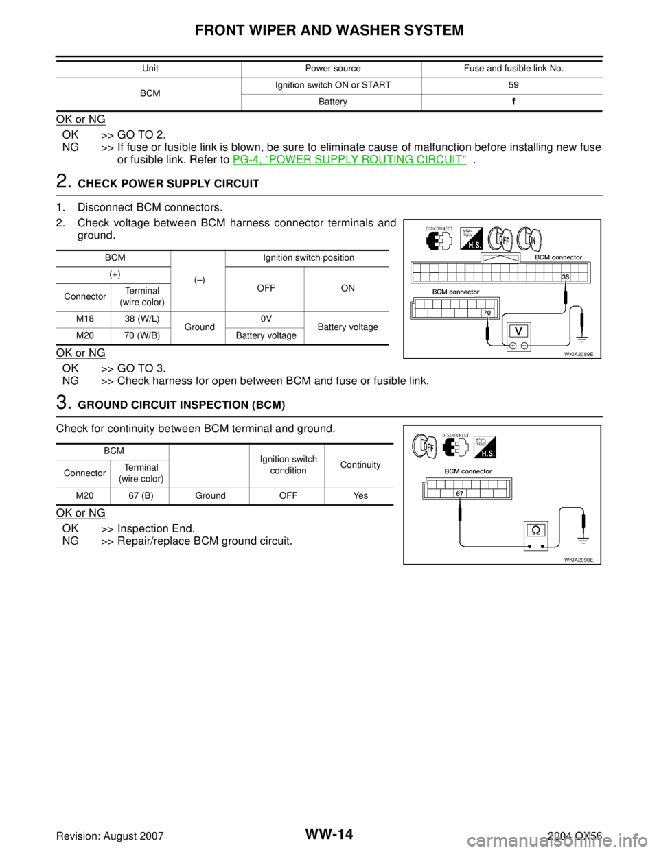
2. CHECK POWER SUPPLY CIRCUIT
1. Disconnect BCM connectors.
2. Check voltage between BCM harness connector terminals and
ground.
OK or NG
OK >> GO TO 3.
NG >> Check harness for open between BCM and fuse or fusible link.
3. GROUND CIRCUIT INSPECTION (BCM)
Check for continuity between BCM terminal and ground.
OK or NG
OK >> Inspection End.
NG >> Repair/replace BCM ground circuit.
BCMIgnition switch ON or START 59
Batteryf Unit Power source Fuse and fusible link No.
BCM
(–)Ignition switch position
(+)
OFF ON
ConnectorTe r m i n a l
(wire color)
M18 38 (W/L)
Ground0V
Battery voltage
M20 70 (W/B) Battery voltage
WKIA2089E
BCM
Ignition switch
conditionContinuity
ConnectorTe r m i n a l
(wire color)
M20 67 (B) Ground OFF Yes
WKIA2090E
Page 3341 of 3371

WW-28
FRONT WIPER AND WASHER SYSTEM
Revision: August 20072004 QX56
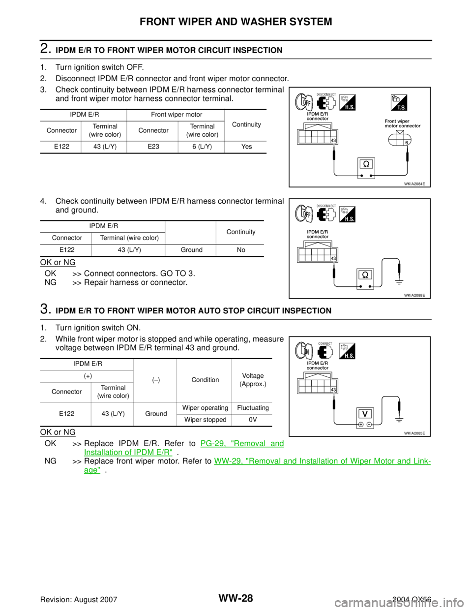
2. IPDM E/R TO FRONT WIPER MOTOR CIRCUIT INSPECTION
1. Turn ignition switch OFF.
2. Disconnect IPDM E/R connector and front wiper motor connector.
3. Check continuity between IPDM E/R harness connector terminal
and front wiper motor harness connector terminal.
4. Check continuity between IPDM E/R harness connector terminal
and ground.
OK or NG
OK >> Connect connectors. GO TO 3.
NG >> Repair harness or connector.
3. IPDM E/R TO FRONT WIPER MOTOR AUTO STOP CIRCUIT INSPECTION
1. Turn ignition switch ON.
2. While front wiper motor is stopped and while operating, measure
voltage between IPDM E/R terminal 43 and ground.
OK or NG
OK >> Replace IPDM E/R. Refer to PG-29, "Removal and
Installation of IPDM E/R" .
NG >> Replace front wiper motor. Refer to WW-29, "
Removal and Installation of Wiper Motor and Link-
age" .
IPDM E/R Front wiper motor
Continuity
ConnectorTe r m i n a l
(wire color)ConnectorTe r m i n a l
(wire color)
E122 43 (L/Y) E23 6 (L/Y) Yes
WKIA2084E
IPDM E/R
Continuity
Connector Terminal (wire color)
E122 43 (L/Y) Ground No
WKIA2088E
IPDM E/R
(–) ConditionVoltag e
(Approx.) (+)
ConnectorTe r m i n a l
(wire color)
E122 43 (L/Y) GroundWiper operating Fluctuating
Wiper stopped 0V
WKIA2085E