Page 2875 of 3371

RSU-16
TROUBLE DIAGNOSIS
Revision: August 20072004 QX56
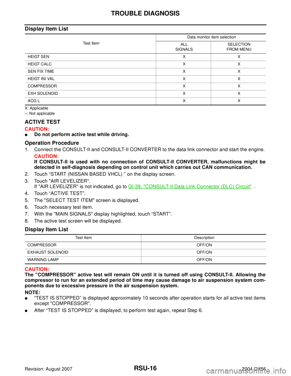
Display Item List
X: Applicable
–: Not applicable
ACTIVE TEST
CAUTION:
�Do not perform active test while driving.
Operation Procedure
1. Connect the CONSULT-II and CONSULT-II CONVERTER to the data link connector and start the engine.
CAUTION:
If CONSULT-II is used with no connection of CONSULT-II CONVERTER, malfunctions might be
detected in self-diagnosis depending on control unit which carries out CAN communication.
2. Touch “START (NISSAN BASED VHCL) ” on the display screen.
3. Touch "AIR LEVELIZER".
If "AIR LEVELIZER" is not indicated, go to GI-39, "
CONSULT-II Data Link Connector (DLC) Circuit" .
4. Touch “ACTIVE TEST”.
5. The "SELECT TEST ITEM" screen is displayed.
6. Touch necessary test item.
7. With the "MAIN SIGNALS" display highlighted, touch “START”.
8. The active test screen will be displayed.
Display Item List
CAUTION:
The "COMPRESSOR" active test will remain ON until it is turned off using CONSULT-II. Allowing the
compressor to run for an extended period of time may cause damage to air suspension system com-
ponents due to excessive pressure in the air suspension system.
NOTE:
�“TEST IS STOPPED” is displayed approximately 10 seconds after operation starts for all active test items
except "COMPRESSOR".
�After “TEST IS STOPPED” is displayed, to perform test again, repeat Step 6.
Te s t I t e mData monitor item selection
ALL
SIGNALSSELECTION
FROM MENU
HEIGT SENXX
HEIGT CALCXX
SEN FIX TIMEXX
HEIGT INI VALXX
COMPRESSOR X X
EXH SOLENOID X X
ACG LXX
Test Item Description
COMPRESSOROFF/ON
EXHAUST SOLENOIDOFF/ON
WARNING LAMPOFF/ON
Page 3098 of 3371
TROUBLE DIAGNOSIS
SRS-37
C
D
E
F
G
I
J
K
L
MA
B
SRS
Revision: August 20072004 QX56
Trouble Diagnosis Without CONSULT-IIEHS000WI
DIAGNOSTIC PROCEDURE 6
Inspect SRS Malfunction Using "AIR BAG" Warning Lamp—Diagnosis Mode
NOTE:
SRS will not enter Diagnosis mode if no malfunction is detected in User mode.
1. Turn ignition switch ON.
2. After “AIR BAG” warning lamp lights for 7 seconds, turn ignition switch OFF within 1 second.
3. Wait more than 3 seconds.
4. Repeat steps 1 to 3 two more times (3 times total).
5. Turn ignition switch ON.
SRS is now in Diagnosis mode.
"AIR BAG" warning lamp operates in Diagnosis mode as follows:
Page 3137 of 3371
TF-12
ALL-MODE 4WD SYSTEM
Revision: August 20072004 QX56
ALL-MODE 4WD TRANSFER BASIC CONTROL
HYDRAULIC CONTROL CIRCUITS
OUTLINE
All-mode 4WD transfer is controlled by the transfer control unit and sensors.
If a malfunction occurs in the all-mode 4WD system, the 4WD warning lamp lights up to indicate the system
malfunction. There are two ways to identify the cause of the malfunction.
1. Performing the self-diagnosis. (The 4WD warning lamp will indicate what kind of malfunction has occurred
by flickering.)
2. Performing diagnosis using CONSULT-II.
LDIA0055E
WDIA0056E
Page 3169 of 3371

TF-44
TROUBLE DIAGNOSIS — INTRODUCTION
Revision: August 20072004 QX56
TROUBLE DIAGNOSIS — INTRODUCTIONPFP:00000
IntroductionEDS0017W
DESCRIPTION
When a malfunction (indicated by the 4WD warning lamp illumination) occurs, collect information first from the
customer about how the malfunction occurs. Then, proceed with the diagnosis presuming it is the cause. Also
inspect the electrical system, paying close attention to other possibilities such as fluid level and leaks.
All-mode 4WD transfer is controlled by transfer control unit and sensors.
If a malfunction occurs in the all-mode 4WD system, the 4WD warning lamp lights up to inform of the system
malfunction. There are two ways to identify the cause of the malfunction.
1. Performing the self-diagnosis. (The 4WD warning lamp will indicate what kind of malfunction has occurred
by flickering.)
2. Performing diagnosis using CONSULT-II.
DIAGNOSTIC WORKSHEET
Information from Customer
KEY POINTS
�WHAT ..... Vehicle model
�WHEN..... Date, Frequencies
�WHERE..... Road conditions
�HOW..... Operating conditions, Symptoms
Diagnostic Worksheet
Information sheet from customer
Customer name MR/MS Model & Year VIN
Transfer model
AT X 1 4 BEngine Mileage
Incident Date Manuf. Date In Service Date
Frequency❏ Continuous ❏ Intermittent ( times a day)
Symptoms❏ 4WD shift indicator lamp does not turn on.
❏ 4WD warning lamp does not turn on.
❏ 4WD shift indicator lamp does not turn off.
❏ ATP warning lamp does not turn on.
❏ 4LO indicator lamp does not turn on.
❏ 4WD shift indicator lamp does not indicate “4H”.
❏ 4WD shift indicator lamp repeats flicking.
❏ Tight corner braking symptom occurs.
❏ 4WD system does not operate.
❏ Others.
4WD warning lamp❏ Continuously lit❏ Not lit
1.❏ Listen to customer complaints.TF-47
2.❏ Check transfer fluid.TF-47
❏ Leakage
❏ Fluid condition
❏ Fluid level
3.❏ Road testingTF-47
❏ 1. Check before engine is started.
❏ 2. Check at idle.
❏ 3. Cruise test
4.❏ Perform self-diagnosis NG items (with CONSULT-II and without CONSULT-II).TF-31
, TF-28
Page 3180 of 3371

TROUBLE DIAGNOSIS — GENERAL DESCRIPTION
TF-55
C
E
F
G
H
I
J
K
L
MA
B
TF
Revision: August 20072004 QX56
TROUBLE DIAGNOSIS — GENERAL DESCRIPTIONPFP:00000
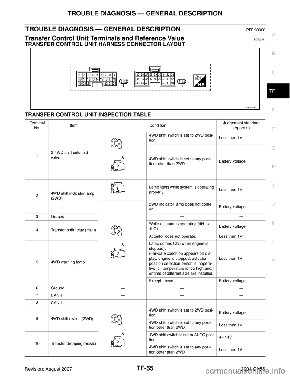
Transfer Control Unit Terminals and Reference ValueEDS00181
TRANSFER CONTROL UNIT HARNESS CONNECTOR LAYOUT
TRANSFER CONTROL UNIT INSPECTION TABLE
LDIA0066E
Te r m i n a l
No.Item ConditionJudgement standard
(Approx.)
12-4WD shift solenoid
valve &4WD shift switch is set to 2WD posi-
tion.Less than 1V
4WD shift switch is set to any posi-
tion other than 2WD.Battery voltage
24WD shift indicator lamp
(2WD)Lamp lights while system is operating
properly.Less than 1V
&2WD indicator lamp does not come
on.Battery voltage
3Ground — —
4 Transfer shift relay (High)While actuator is operating (4H →
4LO)Battery voltage
Actuator does not operate. Less than 1V
5 4WD warning lampLamp comes ON (when engine is
stopped).
(Fail-safe condition appears on dis-
play, engine is stopped, actuator
position detection switch is inopera-
tive, oil temperature is too high and/
or tires of different size are installed.)Less than 1V
Except above Battery voltage
6Ground — — —
7CAN-H — — —
8CAN-L — — —
9 4WD shift switch (2WD)
&4WD shift switch is set to 2WD posi-
tion.Battery voltage
4WD shift switch is set to any posi-
tion other than 2WD.Less than 1V
10 Transfer dropping resistor4WD shift switch is set to AUTO posi-
tion.4 - 14V
4WD shift switch is set to any posi-
tion other than 2WD.Less than 1V