2004 INFINITI QX56 warning light
[x] Cancel search: warning lightPage 2277 of 3371
![INFINITI QX56 2004 Factory Service Manual LAN-14
[CAN]
CAN COMMUNICATION
Revision: August 20072004 QX56
A/C switch/indicator signalTR
RT
Cooling fan speed request signal T R R
Position light request signal R T R
Low beam request signal T R
Lo INFINITI QX56 2004 Factory Service Manual LAN-14
[CAN]
CAN COMMUNICATION
Revision: August 20072004 QX56
A/C switch/indicator signalTR
RT
Cooling fan speed request signal T R R
Position light request signal R T R
Low beam request signal T R
Lo](/manual-img/42/57034/w960_57034-2276.png)
LAN-14
[CAN]
CAN COMMUNICATION
Revision: August 20072004 QX56
A/C switch/indicator signalTR
RT
Cooling fan speed request signal T R R
Position light request signal R T R
Low beam request signal T R
Low beam status signal RT
High beam request signal R T R
High beam status signal RT
Front fog light request signal T R
Day time running light request
signalTR
Vehicle speed signalR RRT
RRR R T R R R
Sleep wake up signal R T R
Door switch signal R R R T R
Turn indicator signal R T
Key fob ID signal R T
Key fob door unlock signal R T
Buzzer output signalRT
TR
Fuel level sensor signal R T
Malfunction indicator lamp signal T R
Fuel level low warning signal T R
Front wiper request signal R T R
Front wiper stop position signal R T
Rear window defogger switch sig-
nalTR R
Rear window defogger control
signalRRRT
Hood switch signalRT
Theft warning horn request signal T R
Horn chirp signalTR
Steering angle sensor signal T R
ABS warning lamp signal R T
VDC OFF indicator lamp signal R R T
SLIP indicator lamp signal R T
Brake warning lamp signal R T
VDC operation signal R T
ABS malfunction signal R TSignals ECM TCMICC
sen-
sorICC
unitDriver
seat
con-
trol
unitCom-
bina-
tion
mete
rDis-
play
con-
trol
unitBCMStee r-
ing
angle
sen-
sorFront
air
con-
trolTran s -
fer
con-
trol
unitABS
actu-
ator
and
elec-
tric
unit
(con-
trol
unit)IPD
M
E/R
Page 2433 of 3371

LT-2Revision: August 20072004 QX56 COMBINATION SWITCH READING FUNCTION ... 48
EXTERIOR LAMP BATTERY SAVER CONTROL ... 48
DELAY TIMER FUNCTION ................................. 48
CAN Communication System Description .............. 48
Major Components and Functions .......................... 48
Schematic ............................................................... 49
Wiring Diagram — AUTO/L — ................................ 50
Terminals and Reference Values for BCM .............. 53
Terminals and Reference Values for IPDM E/R ...... 54
How to Proceed With Trouble Diagnosis ................ 55
Preliminary Check .................................................. 55
SETTING CHANGE FUNCTIONS ....................... 55
CHECK POWER SUPPLY AND GROUND CIR-
CUIT .................................................................... 55
CONSULT-II Function (BCM) .................................. 57
CONSULT-II OPERATION ................................... 57
WORK SUPPORT ............................................... 58
DATA MONITOR .................................................. 58
ACTIVE TEST ..................................................... 59
SELF-DIAGNOSTIC RESULTS ........................... 59
CONSULT-II Function (IPDM E/R) .......................... 60
CONSULT-II OPERATION ................................... 60
DATA MONITOR .................................................. 61
ACTIVE TEST ..................................................... 61
Trouble Diagnosis Chart by Symptom .................... 62
Lighting Switch Inspection ...................................... 62
Optical Sensor System Inspection .......................... 63
Removal and Installation of Optical Sensor ............ 64
REMOVAL ........................................................... 64
INSTALLATION .................................................... 64
HEADLAMP AIMING CONTROL .............................. 65
System Description ................................................. 65
Wiring Diagram — H/AIM — ................................... 66
Removal and Installation ........................................ 68
Switch Circuit Inspection ........................................ 68
FRONT FOG LAMP .................................................. 69
Component Parts and Harness Connector Location ... 69
System Description ................................................. 69
OUTLINE ............................................................. 69
COMBINATION SWITCH READING FUNCTION ... 70
EXTERIOR LAMP BATTERY SAVER CONTROL ... 70
CAN Communication System Description .............. 70
Wiring Diagram — F/FOG — .................................. 71
Terminals and Reference Values for BCM .............. 73
Terminals and Reference Values for IPDM E/R ...... 74
How to Proceed With Trouble Diagnosis ................ 74
Preliminary Check .................................................. 75
CHECK POWER SUPPLY AND GROUND CIR-
CUIT .................................................................... 75
CONSULT-II Functions ........................................... 76
Front Fog Lamps Do Not Illuminate (Both Sides) ... 76
Front Fog Lamp Does Not Illuminate (One Side) ... 77
Aiming Adjustment .................................................. 78
Bulb Replacement .................................................. 79
Removal and Installation ........................................ 79
TURN SIGNAL AND HAZARD WARNING LAMPS ... 80
Component Parts and Harness Connector Location ... 80
System Description ................................................. 80
OUTLINE ............................................................. 80TURN SIGNAL OPERATION ...............................80
HAZARD LAMP OPERATION .............................81
REMOTE KEYLESS ENTRY SYSTEM OPERA-
TION ....................................................................82
COMBINATION SWITCH READING FUNCTION ...82
CAN Communication System Description ..............82
Wiring Diagram — TURN — ...................................83
Terminals and Reference Values for BCM ..............85
How to Proceed With Trouble Diagnosis ................86
Preliminary Check ...................................................87
CHECK POWER SUPPLY AND GROUND CIR-
CUIT .....................................................................87
CONSULT-II Function (BCM) ..................................88
CONSULT-II OPERATION ...................................88
DATA MONITOR ..................................................89
ACTIVE TEST ......................................................89
Turn Signal Lamp Does Not Operate ......................90
Rear Turn Signal Lamp Does Not Operate .............91
Hazard Warning Lamp Does Not Operate But Turn
Signal Lamps Operate ............................................92
Turn Signal Indicator Lamp Does Not Operate .......93
Bulb Replacement (Front Turn Signal Lamp) ..........94
Bulb Replacement (Rear Turn Signal Lamp) ..........94
Removal and Installation of Front Turn Signal Lamp ...94
Removal and Installation of Rear Turn Signal Lamp ...94
LIGHTING AND TURN SIGNAL SWITCH ................95
Removal and Installation .........................................95
REMOVAL ............................................................95
INSTALLATION ....................................................95
HAZARD SWITCH .....................................................96
Removal and Installation .........................................96
REMOVAL ............................................................96
INSTALLATION ....................................................96
COMBINATION SWITCH ..........................................97
Wiring Diagram — COMBSW — ............................97
Combination Switch Reading Function ...................98
CONSULT-II Function (BCM) ..................................98
CONSULT-II OPERATION ...................................98
DATA MONITOR ..................................................99
Combination Switch Inspection ............................. 100
Removal and Installation ....................................... 102
Switch Circuit Inspection ....................................... 102
STOP LAMP ............................................................ 103
System Description ............................................... 103
Wiring Diagram — STOP/L — .............................. 104
High-Mounted Stop Lamp ..................................... 105
BULB REPLACEMENT ...................................... 105
REMOVAL AND INSTALLATION ....................... 105
Stop Lamp ............................................................. 105
BULB REPLACEMENT ...................................... 105
REMOVAL AND INSTALLATION ....................... 105
BACK-UP LAMP ..................................................... 106
Wiring Diagram — BACK/L — .............................. 106
Bulb Replacement ................................................. 107
Removal and Installation ....................................... 107
PARKING, LICENSE PLATE AND TAIL LAMPS .... 108
Component Parts and Harness Connector Location . 108
System Description ............................................... 108
OPERATION BY LIGHTING SWITCH ............... 109
Page 2516 of 3371

TURN SIGNAL AND HAZARD WARNING LAMPS
LT-85
C
D
E
F
G
H
I
J
L
MA
B
LT
Revision: August 20072004 QX56
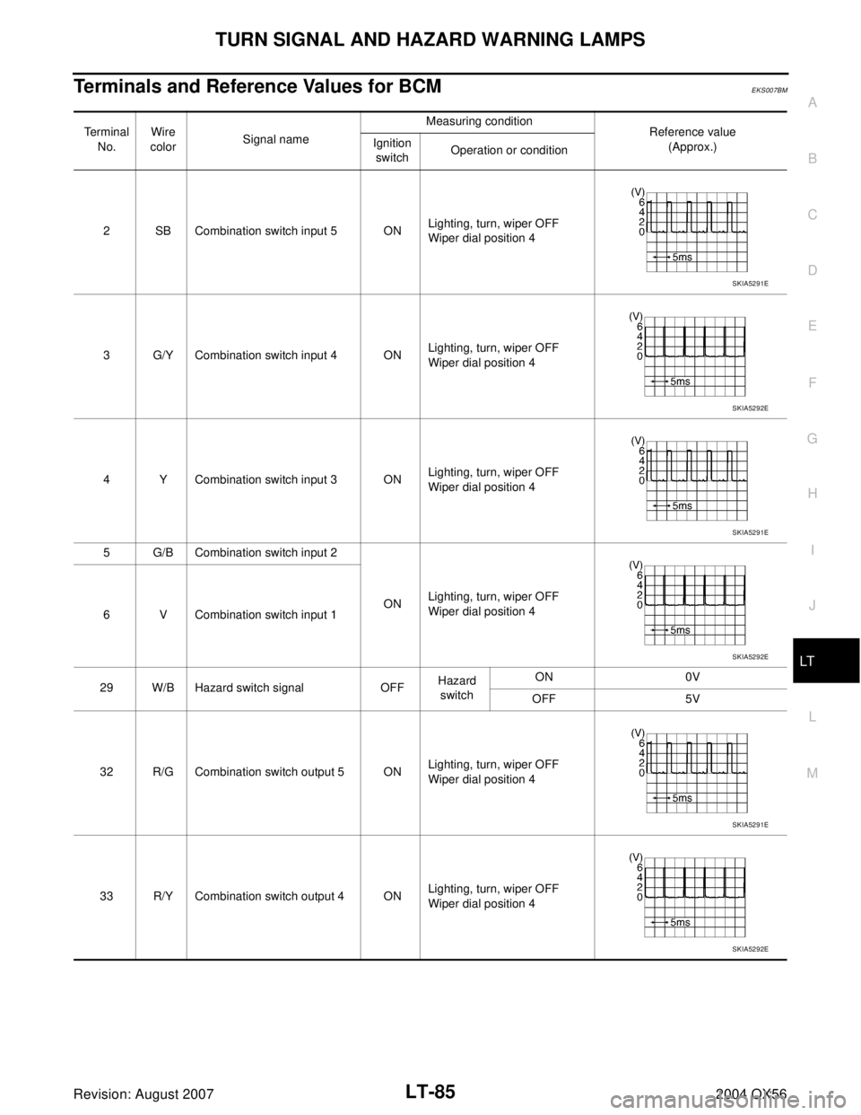
Terminals and Reference Values for BCMEKS007BM
Terminal
No.Wire
colorSignal nameMeasuring condition
Reference value
(Approx.) Ignition
switchOperation or condition
2 SB Combination switch input 5 ONLighting, turn, wiper OFF
Wiper dial position 4
3 G/Y Combination switch input 4 ONLighting, turn, wiper OFF
Wiper dial position 4
4 Y Combination switch input 3 ONLighting, turn, wiper OFF
Wiper dial position 4
5 G/B Combination switch input 2
ONLighting, turn, wiper OFF
Wiper dial position 4
6 V Combination switch input 1
29 W/B Hazard switch signal OFFHazard
switchON 0V
OFF 5V
32 R/G Combination switch output 5 ONLighting, turn, wiper OFF
Wiper dial position 4
33 R/Y Combination switch output 4 ONLighting, turn, wiper OFF
Wiper dial position 4
SKIA5291E
SKIA5292E
SKIA5291E
SKIA5292E
SKIA5291E
SKIA5292E
Page 2517 of 3371

LT-86
TURN SIGNAL AND HAZARD WARNING LAMPS
Revision: August 20072004 QX56
How to Proceed With Trouble DiagnosisEKS007BN
1. Confirm the symptom or customer complaint.
2. Understand operation description and function description. Refer to LT-80, "
System Description" .
3. Perform preliminary check. Refer to LT-87, "
Preliminary Check" .
4. Check symptom and repair or replace the cause of malfunction.
5. Do turn signal and hazard warning lamps operate normally? If YES: GO TO 6. If NO: GO TO 4.
6. Inspection End.
34 L Combination switch output 3 ONLighting, turn, wiper OFF
Wiper dial position 4
35 O/B Combination switch output 2
ONLighting, turn, wiper OFF
Wiper dial position 4
36 R/W Combination switch output 1
38 W/L Ignition switch (ON) ON — Battery voltage
39 W CAN-H — — —
40 R CAN-L — — —
60 G/B Turn signal (left) ONCombina-
tion switchTu rn le ft O N
61 G/Y Turn signal (right) ONCombina-
tion switchTurn right ON
67 B Ground ON — 0V
70 W/B Battery power supply OFF — Battery voltage Te r m i n a l
No.Wire
colorSignal nameMeasuring condition
Reference value
(Approx.) Ignition
switchOperation or condition
SKIA5291E
SKIA5292E
SKIA3009J
SKIA3009J
Page 2520 of 3371

TURN SIGNAL AND HAZARD WARNING LAMPS
LT-89
C
D
E
F
G
H
I
J
L
MA
B
LT
Revision: August 20072004 QX56
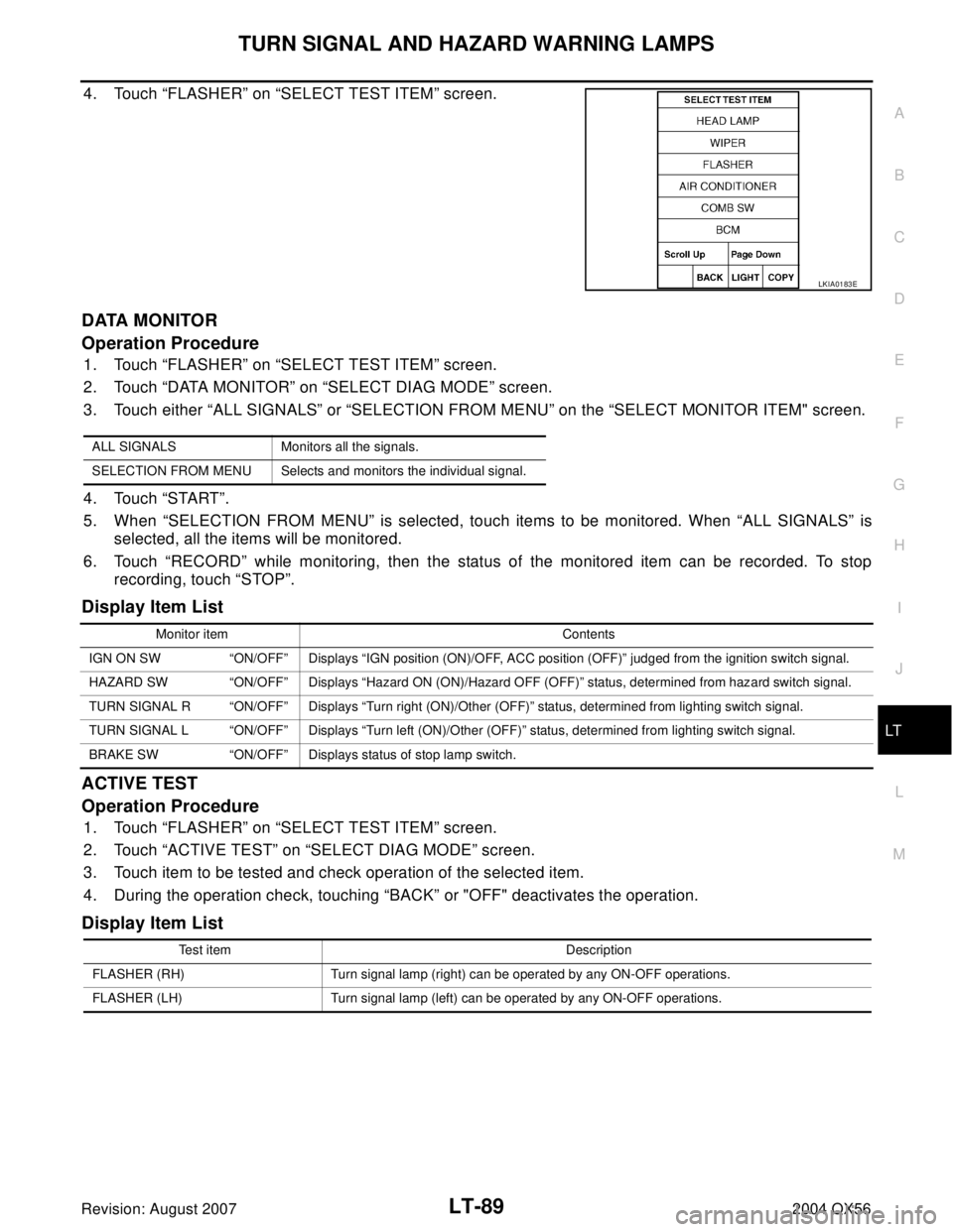
4. Touch “FLASHER” on “SELECT TEST ITEM” screen.
DATA MONITOR
Operation Procedure
1. Touch “FLASHER” on “SELECT TEST ITEM” screen.
2. Touch “DATA MONITOR” on “SELECT DIAG MODE” screen.
3. Touch either “ALL SIGNALS” or “SELECTION FROM MENU” on the “SELECT MONITOR ITEM" screen.
4. Touch “START”.
5. When “SELECTION FROM MENU” is selected, touch items to be monitored. When “ALL SIGNALS” is
selected, all the items will be monitored.
6. Touch “RECORD” while monitoring, then the status of the monitored item can be recorded. To stop
recording, touch “STOP”.
Display Item List
ACTIVE TEST
Operation Procedure
1. Touch “FLASHER” on “SELECT TEST ITEM” screen.
2. Touch “ACTIVE TEST” on “SELECT DIAG MODE” screen.
3. Touch item to be tested and check operation of the selected item.
4. During the operation check, touching “BACK” or "OFF" deactivates the operation.
Display Item List
LKIA0183E
ALL SIGNALS Monitors all the signals.
SELECTION FROM MENU Selects and monitors the individual signal.
Monitor item Contents
IGN ON SW “ON/OFF” Displays “IGN position (ON)/OFF, ACC position (OFF)” judged from the ignition switch signal.
HAZARD SW “ON/OFF” Displays “Hazard ON (ON)/Hazard OFF (OFF)” status, determined from hazard switch signal.
TURN SIGNAL R “ON/OFF” Displays “Turn right (ON)/Other (OFF)” status, determined from lighting switch signal.
TURN SIGNAL L “ON/OFF” Displays “Turn left (ON)/Other (OFF)” status, determined from lighting switch signal.
BRAKE SW “ON/OFF” Displays status of stop lamp switch.
Test item Description
FLASHER (RH) Turn signal lamp (right) can be operated by any ON-OFF operations.
FLASHER (LH) Turn signal lamp (left) can be operated by any ON-OFF operations.
Page 2521 of 3371

LT-90
TURN SIGNAL AND HAZARD WARNING LAMPS
Revision: August 20072004 QX56
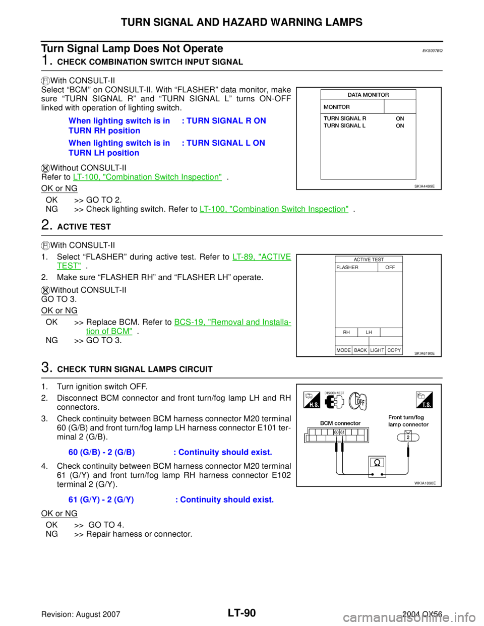
Turn Signal Lamp Does Not OperateEKS007BQ
1. CHECK COMBINATION SWITCH INPUT SIGNAL
With CONSULT-II
Select “BCM” on CONSULT-II. With “FLASHER” data monitor, make
sure “TURN SIGNAL R” and “TURN SIGNAL L” turns ON-OFF
linked with operation of lighting switch.
Without CONSULT-II
Refer to LT- 1 0 0 , "
Combination Switch Inspection" .
OK or NG
OK >> GO TO 2.
NG >> Check lighting switch. Refer to LT-100, "
Combination Switch Inspection" .
2. ACTIVE TEST
With CONSULT-II
1. Select “FLASHER” during active test. Refer to LT-89, "
ACTIVE
TEST" .
2. Make sure “FLASHER RH” and “FLASHER LH” operate.
Without CONSULT-II
GO TO 3.
OK or NG
OK >> Replace BCM. Refer to BCS-19, "Removal and Installa-
tion of BCM" .
NG >> GO TO 3.
3. CHECK TURN SIGNAL LAMPS CIRCUIT
1. Turn ignition switch OFF.
2. Disconnect BCM connector and front turn/fog lamp LH and RH
connectors.
3. Check continuity between BCM harness connector M20 terminal
60 (G/B) and front turn/fog lamp LH harness connector E101 ter-
minal 2 (G/B).
4. Check continuity between BCM harness connector M20 terminal
61 (G/Y) and front turn/fog lamp RH harness connector E102
terminal 2 (G/Y).
OK or NG
OK >> GO TO 4.
NG >> Repair harness or connector.When lighting switch is in
TURN RH position: TURN SIGNAL R ON
When lighting switch is in
TURN LH position: TURN SIGNAL L ON
SKIA4499E
SKIA6190E
60 (G/B) - 2 (G/B) : Continuity should exist.
61 (G/Y) - 2 (G/Y) : Continuity should exist.
WKIA1890E
Page 2681 of 3371

PG-22
IPDM E/R (INTELLIGENT POWER DISTRIBUTION MODULE ENGINE ROOM)
Revision: August 20072004 QX56
All Signals, Main Signals, Selection From Menu
NOTE:
Perform monitoring of IPDM E/R data with the ignition switch ON. When the ignition switch is in ACC position,
display may not be correct.
ACTIVE TEST
Operation Procedure
1. Touch “ACTIVE TEST” on “SELECT DIAG-MODE” screen.
2. Touch item to be tested, and check operation.
3. Touch “START”.
4. Touch "STOP" while testing to stop the operation.
Item nameCONSULT-II
screen displayDisplay or unitMonitor item selection
Description
ALL
SIGNALSMAIN
SIGNALSSELECTION
FROM MENU
Motor fan requestMOTOR FAN
REQ1/2/3/4 X X X Signal status input from ECM
Compressor request AC COMP REQ ON/OFF X X X Signal status input from ECM
Position lights
requestTAIL & CLR REQ ON/OFF X X X Signal status input from BCM
Headlamp low beam
requestHL LO REQ ON/OFF X X X Signal status input from BCM
Headlamp high
beam requestHL HI REQ ON/OFF X X X Signal status input from BCM
Front fog lghts
requestFR FOG REQ ON/OFF X X X Signal status input from BCM
Front wiper request FR WIP REQSTOP/1LOW/
LOW/HIX X X Signal status input from BCM
Wiper auto stopWIP AUTO
STOPACT P/STOP P X X X Output status of IPDM E/R
Wiper protection WIP PROT OFF/Block X X X Control status of IPDM E/R
Starter request ST RLY REQ ON/OFF X X
Status of input signal
NOTE
Ignition relay
statusIGN RLY ON/OFF X X XIgnition relay status monitored
with IPDM E/R
Rear defogger
requestRR DEF REQ ON/OFF X X X Signal status input from BCM
Oil pressure switch OIL P SW OPEN/CLOSE X XSignal status input from IPDM
E/R (function is not enabled)
Hood switch HOOD SW OFF XSignal status input from IPDM
E/R (function is not enabled)
Theft warning horn
requestTHFT HRN REQ ON/OFF X X Signal status input from BCM
Horn chirp HORN CHIRP ON/OFF X X Output status of IPDM E/R
Daytime running
lamp requestDTRL REQ ON/OFF X X Signal status input from BCM
Test name CONSULT-II screen display Description
Rear defogger output REAR DEFOGGERWith a certain ON-OFF operation, the rear defogger relay can be oper-
ated.
Front wiper (HI, LO) output FRONT WIPERWith a certain operation (OFF, HI, LO), the front wiper relay (Lo, Hi)
can be operated.
Cooling fan output MOTOR FAN With a certain operation (1, 2, 3, 4), the cooling fan can be operated.
Lamp (HI, LO, TAIL, FOG)
outputEXTERNAL LAMPSWith a certain operation (OFF, TAIL, LO, HI, FOG), the lamp relay
(Low, High, Tail, Fog) can be operated.
Page 2720 of 3371

HARNESS
PG-61
C
D
E
F
G
H
I
J
L
MA
B
PG
Revision: August 20072004 QX56
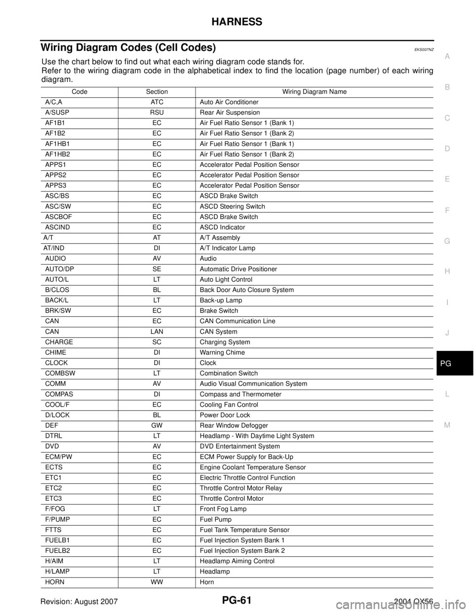
Wiring Diagram Codes (Cell Codes)EKS007NZ
Use the chart below to find out what each wiring diagram code stands for.
Refer to the wiring diagram code in the alphabetical index to find the location (page number) of each wiring
diagram.
Code Section Wiring Diagram Name
A/C,A ATC Auto Air Conditioner
A/SUSP RSU Rear Air Suspension
AF1B1 EC Air Fuel Ratio Sensor 1 (Bank 1)
AF1B2 EC Air Fuel Ratio Sensor 1 (Bank 2)
AF1HB1 EC Air Fuel Ratio Sensor 1 (Bank 1)
AF1HB2 EC Air Fuel Ratio Sensor 1 (Bank 2)
APPS1 EC Accelerator Pedal Position Sensor
APPS2 EC Accelerator Pedal Position Sensor
APPS3 EC Accelerator Pedal Position Sensor
ASC/BS EC ASCD Brake Switch
ASC/SW EC ASCD Steering Switch
ASCBOF EC ASCD Brake Switch
ASCIND EC ASCD Indicator
A/T AT A/T Assembly
AT/IND DI A/T Indicator Lamp
AUDIO AV Audio
AUTO/DP SE Automatic Drive Positioner
AUTO/L LT Auto Light Control
B/CLOS BL Back Door Auto Closure System
BACK/L LT Back-up Lamp
BRK/SW EC Brake Switch
CAN EC CAN Communication Line
CAN LAN CAN System
CHARGE SC Charging System
CHIME DI Warning Chime
CLOCK DI Clock
COMBSW LT Combination Switch
COMM AV Audio Visual Communication System
COMPAS DI Compass and Thermometer
COOL/F EC Cooling Fan Control
D/LOCK BL Power Door Lock
DEF GW Rear Window Defogger
DTRL LT Headlamp - With Daytime Light System
DVD AV DVD Entertainment System
ECM/PW EC ECM Power Supply for Back-Up
ECTS EC Engine Coolant Temperature Sensor
ETC1 EC Electric Throttle Control Function
ETC2 EC Throttle Control Motor Relay
ETC3 EC Throttle Control Motor
F/FOG LT Front Fog Lamp
F/PUMP EC Fuel Pump
FTTS EC Fuel Tank Temperature Sensor
FUELB1 EC Fuel Injection System Bank 1
FUELB2 EC Fuel Injection System Bank 2
H/AIM LT Headlamp Aiming Control
H/LAMP LT Headlamp
HORN WW Horn