Page 3226 of 3371

REAR OIL SEAL
TF-101
C
E
F
G
H
I
J
K
L
MA
B
TF
Revision: August 20072004 QX56
REAR OIL SEALPFP:33140
Removal and InstallationEDS00316
REMOVAL
1. Partially drain the transfer fluid. Refer to MA-24, "Changing Transfer Fluid" .
2. Remove the rear propeller shaft. Refer to PR-8, "
Removal and Installation" .
3. Remove the dust cover from the rear case.
CAUTION:
Do not damage the rear case.
4. Remove the rear oil seal from the rear case, using Tool.
CAUTION:
Do not damage the rear case.
INSTALLATION
1. Install the oil seal until it is flush with the end face of the rear
case, using Tool.
CAUTION:
�Do not reuse oil seal.
�Apply petroleum jelly to oil seal.
2. Apply petroleum jelly to the circumference of the new dust cover.
Position the dust cover using the identification mark as shown.
CAUTION:
�Do not reuse dust cover.
�Position the identification mark at the position shown.
WDIA0127E
Tool number : ST33290001 (J-34286)
LDIA0139E
Tool number : ST30720000 (J-25405)
LDIA0140E
SDIA2208E
Page 3227 of 3371
TF-102
REAR OIL SEAL
Revision: August 20072004 QX56
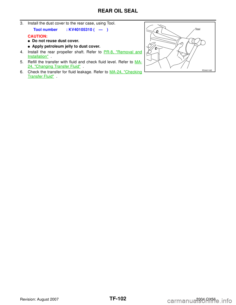
3. Install the dust cover to the rear case, using Tool.
CAUTION:
�Do not reuse dust cover.
�Apply petroleum jelly to dust cover.
4. Install the rear propeller shaft. Refer to PR-8, "
Removal and
Installation" .
5. Refill the transfer with fluid and check fluid level. Refer to MA-
24, "Changing Transfer Fluid" .
6. Check the transfer for fluid leakage. Refer to MA-24, "
Checking
Transfer Fluid" . Tool number : KV40105310 ( — )
PDIA0 116 E
Page 3233 of 3371
TF-108
TRANSFER OIL FILTER
Revision: August 20072004 QX56
3. Apply ATF to the two new O-rings (1), and install them on the oil
filter (2).
CAUTION:
Do not reuse O-rings.
4. Install the oil filter to the transfer assembly. Tighten the bolts to
the specified torque. Refer to TF-110, "
Transfer Components" .
CAUTION:
�Do not damage oil filter.
�Attach oil filter and tighten bolts evenly.
5. Check the transfer fluid. Refer to MA-24, "
Checking Transfer
Fluid" .
6. Start the engine for one minute. Then stop the engine and
recheck the transfer fluid.
WDIA0285E
SDIA2136E
Page 3245 of 3371
TF-120
CENTER CASE
Revision: August 20072004 QX56
3. Remove control valve assembly bolts.
4. Remove snap ring. Then push connector assembly into center
case to remove control valve assembly.
5. Remove lip seals from center case.
CAUTION:
There are two kinds of lip seals (lip seal of large inner diam-
eter: 5 pieces, lip seal of small inner diameter: 2 pieces).
Confirm the position before disassembly.
6. Remove all bolts except for the two as shown.
7. Remove 4WD solenoid valve, clutch pressure switch, 2-4WD
shift solenoid valve, line pressure switch, and transfer fluid tem-
perature sensor from control valve assembly.
SDIA2121E
SDIA2122E
SDIA2123E
SDIA2124E
PDIA0183E
Page 3259 of 3371

TF-134
CENTER CASE
Revision: August 20072004 QX56
CONTROL VALVE
�Check resistance between terminals of 4WD solenoid valve, 2-
4WD shift solenoid valve and transfer fluid temperature sensor.
Refer to TF-95, "
Component Inspection" .
�Check sliding faces of control valves and plugs for abnormality.
If any is found, replace the control valve assembly with new one.
Refer to TF-154, "
Control Valve" .
CAUTION:
Replace control valve body together with clutch return
spring as a set.
�Check each control valve spring for damage or distortion, and
also check its free length, outer diameter and wire diameter. If
any damage or fatigue is found, replace control valve body with
new one. Refer to TF-154, "
Control Valve" .
CAUTION:
Replace control valve body together with clutch return spring
as a set.
CLUTCH
�Check drive plate facings and driven plate for damage, cracks or
other abnormality. If any abnormalities are found, replace with
new one.
�Check the thickness of drive plate facings and driven plate.
Refer to TF-153, "
CLUTCH" .
CAUTION:
�Measure facing thickness at 3 points to take an average.
�Check all the drive and driven plates.
�Check return spring for damage or deformation.
�Do not remove spring from the plate
PDIA0183E
SMT947C
SMT948C
SMT949C
Page 3275 of 3371

TF-150
ASSEMBLY
Revision: August 20072004 QX56
4. Install center case assembly to front case assembly.
CAUTION:
Pay careful attention so that mainshaft end is not damaged.
5. Tap center case lightly press-fit front drive shaft bearing into
front case, using suitable tool.
6. Tighten front case bolts to specified torque.
NOTE:
Be sure to install air breather hose clamp, connector bracket
and harness clip.
7. Remove all the gasket fluid from switch mounting area and
inside center case. With ATP switch and neutral-4LO switch
threaded in 1 to 2 pitches, apply specified sealant or equivalent
to the thread of the switches and tighten to specified torque.
Refer to GI-45, "
Recommended Chemical Products and Seal-
ants" .
8. Apply ATF or petroleum jelly to stem bleeder and install to center
case.
9. Install main oil pump assembly to the center case assembly and tighten bolts. Refer to TF-110, "
Transfer
Components" .
SDIA2138E
Front case bolts : 45 N·m (4.6 kg-m, 33 ft-lb)
SDIA2100E
ATP and Neutral- 4LO
switches: 28 N·m (2.9 kg-m, 21 ft-lb)
SDIA2096E
SDIA2097E
Page 3278 of 3371

TF-153
C
E
F
G
H
I
J
K
L
MA
B
TF
Revision: August 20072004 QX56
SERVICE DATA AND SPECIFICATIONS (SDS)PFP:00030
General SpecificationsEDS0031B
Inspection and Adjus")
SERVICE DATA AND SPECIFICATIONS (SDS)
TF-153
C
E
F
G
H
I
J
K
L
MA
B
TF
Revision: August 20072004 QX56
SERVICE DATA AND SPECIFICATIONS (SDS)PFP:00030
General SpecificationsEDS0031B
Inspection and AdjustmentEDS0031C
CLEARANCE BETWEEN INNER GEAR AND OUTER GEAR
Unit: mm (in)
CLUTCH
Unit: mm (in)
PINION GEAR END PLAY
Unit: mm (in)
CLEARANCE BETWEEN SHIFT FORK AND SLEEVE
Unit: mm (in)
SELECTIVE PARTS
Sub-oil Pump
Unit: mm (in)
*: Always check with the Parts Department for the latest parts information.
Main Oil Pump
Unit: mm (in) Applied modelVK56DE
Transfer modelATX14B
Fluid capacity (Approx.)
(US qt, lmp qt)3.0 (3-1/8, 2-5/8)
Gear ratioHigh 1.000
Low 2.596
Number of teethPlanetary
gearSun gear 57
Internal gear 91
Front drive sprocket 38
Front drive shaft 38
Item Specification
Sub-oil pump 0.015 - 0.035 (0.0006 - 0.0014)
Main oil pump 0.015 - 0.035 (0.0006 - 0.0014)
Item Limit value
Drive plate1.4 (0.055)
Item Standard
Pinion gear end play 0.1 - 0.7 (0.004 - 0.028)
Item Standard
Shift fork and sleeve Less than 0.36 (0.0142)
Gear thicknessPart number*
Inner gear Outer gear
9.27 - 9.28 (0.3650 - 0.3654) 31346 0W462 31347 0W462
9.28 - 9.29 (0.3654 - 0.3657) 31346 0W461 31347 0W461
9.29 - 9.30 (0.3657 - 0.3661) 31346 0W460 31347 0W460
Gear thicknessPart number*
Inner gear Outer gear
8.27 - 8.28 (0.3256 - 0.3260) 31346 7S112 31347 7S112
8.28 - 8.29 (0.3260 - 0.3264) 31346 7S111 31347 7S111
8.29 - 8.30 (0.3264 - 0.3268) 31346 7S110 31347 7S110
, and install them on the oil
filter (2).
CAUTION:
Do not reuse O-rings.
4. Install the oil filter to t")
