Page 2265 of 3371

LAN-2Revision: August 20072004 QX56 IPDM E/R Ignition Relay Circuit Check ................... 89
Component Inspection ............................................ 89
ECM/IPDM E/R INTERNAL CIRCUIT INSPEC-
TION .................................................................... 89
CAN SYSTEM (TYPE 3) ........................................... 90
System Description ................................................. 90
Component Parts and Harness Connector Location ... 90
Schematic ............................................................... 91
Wiring Diagram - CAN - .......................................... 92
Work Flow ............................................................... 95
CHECK SHEET ................................................... 97
CHECK SHEET RESULTS (EXAMPLE) ............. 99
Circuit Check Between TCM and Driver Seat Con-
trol Unit .................................................................115
Circuit Check Between Driver Seat Control Unit and
Data Link Connector .............................................116
Circuit Check Between Data Link Connector and
IPDM E/R ..............................................................117
ECM Circuit Check ...............................................118
TCM Circuit Check ...............................................118
Driver Seat Control Unit Circuit Check .................119
Combination Meter Circuit Check .........................119
Display Control Unit Circuit Check ........................120
BCM Circuit Check ...............................................120
Data Link Connector Circuit Check .......................121
Steering Angle Sensor Circuit Check ...................121
Front Air Control Circuit Check .............................122
Transfer Control Unit Circuit Check ......................122
ABS Actuator and Electric Unit (Control Unit) Circuit
Check ...................................................................123
IPDM E/R Circuit Check .......................................123
CAN Communication Circuit Check ......................124
IPDM E/R Ignition Relay Circuit Check .................124
Component Inspection ..........................................125
ECM/IPDM E/R INTERNAL CIRCUIT INSPEC-
TION ..................................................................125CAN SYSTEM (TYPE 4) .......................................... 126
System Description ............................................... 126
Component Parts and Harness Connector Location . 126
Schematic ............................................................. 127
Wiring Diagram - CAN - ........................................ 128
Work Flow ............................................................. 131
CHECK SHEET ................................................. 133
CHECK SHEET RESULTS (EXAMPLE) ............ 135
Circuit Check Between TCM and ICC Sensor ...... 155
Circuit Check Between ICC Sensor and ICC Unit . 156
Circuit Check Between ICC Unit and Driver Seat
Control Unit ........................................................... 157
Circuit Check Between Driver Seat Control Unit and
Data Link Connector ............................................. 157
Circuit Check Between Data Link Connector and
IPDM E/R .............................................................. 158
ECM Circuit Check ................................................ 159
TCM Circuit Check ................................................ 159
ICC Sensor Circuit Check ..................................... 160
ICC Unit Circuit Check .......................................... 160
Driver Seat Control Unit Circuit Check .................. 161
Combination Meter Circuit Check ......................... 161
Display Control Unit Circuit Check ........................ 162
BCM Circuit Check ................................................ 162
Data Link Connector Circuit Check ....................... 163
Steering Angle Sensor Circuit Check .................... 163
Front Air Control Circuit Check ............................. 164
Transfer Control Unit Circuit Check ...................... 164
ABS Actuator and Electric Unit (Control Unit) Circuit
Check .................................................................... 165
IPDM E/R Circuit Check ........................................ 165
CAN Communication Circuit Check ...................... 166
IPDM E/R Ignition Relay Circuit Check ................. 166
Component Inspection .......................................... 167
ECM/IPDM E/R INTERNAL CIRCUIT INSPEC-
TION .................................................................. 167
Page 2273 of 3371
LAN-10
[CAN]
CAN COMMUNICATION
Revision: August 20072004 QX56
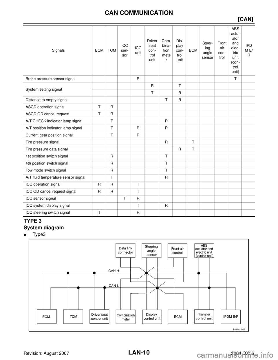
TYPE 3
System diagram
�Type3
Brake pressure sensor signal R T
System setting signalRT
TR
Distance to empty signal T R
ASCD operation signal T R
ASCD OD cancel request T R
A/T CHECK indicator lamp signal T R
A/T position indicator lamp signal T R R
Current gear position signal T R
Tire pressure signal R T
Tire pressure data signal R T
1st position switch signal R T
4th position switch signal R T
Tow mode switch signal R T
A/T fluid temperature sensor signal T R
ICC operation signal R R T
ICC OD cancel request signal R R T
ICC sensor signal T R
ICC system display signal T R
ICC steering switch signal T RSignals ECM TCMICC
sen-
sorICC
unitDriver
seat
con-
trol
unitCom-
bina-
tion
mete
rDis-
play
con-
trol
unitBCMSteer-
ing
angle
sensorFront
air
con-
trol ABS
actu-
ator
and
elec-
tric
unit
(con-
trol
unit)IPD
M E/
R
PKIA8174E
Page 2278 of 3371
CAN COMMUNICATION
LAN-15
[CAN]
C
D
E
F
G
H
I
J
L
MA
B
LAN
Revision: August 20072004 QX56
TCS malfunction signal R T
VDC malfunction signal R T
Brake pressure sensor signal R T
System setting signalRT
TR
Distance to empty signal T R
ASCD operation signal T R
ASCD OD cancel request T R
A/T CHECK indicator lamp signal T R
A/T position indicator lamp signal T R R R
Current gear position signal T R
Tire pressure signal R T
Tire pressure data signal R T
1st position switch signal R T
4th position switch signal R T
Tow mode switch signal R T
A/T fluid temperature sensor sig-
nalTR
ICC operation signal R R T
ICC OD cancel request signal R R T
ICC sensor signal T R
ICC system display signal T R
ICC steering switch signal T RSignals ECM TCMICC
sen-
sorICC
unitDriver
seat
con-
trol
unitCom-
bina-
tion
mete
rDis-
play
con-
trol
unitBCMStee r-
ing
angle
sen-
sorFront
air
con-
trolTra ns -
fer
con-
trol
unitABS
actu-
ator
and
elec-
tric
unit
(con-
trol
unit)IPD
M
E/R
Page 2284 of 3371
![INFINITI QX56 2004 Factory Service Manual CAN SYSTEM (TYPE 1)
LAN-21
[CAN]
C
D
E
F
G
H
I
J
L
MA
B
LAN
Revision: August 20072004 QX56
Work FlowUKS0018G
1. When there are no indications of “AUTO DRIVE POS.”, “BCM” or “IPDM E/R” on �](/manual-img/42/57034/w960_57034-2283.png "INFINITI QX56 2004 Factory Service Manual CAN SYSTEM (TYPE 1)
LAN-21
[CAN]
C
D
E
F
G
H
I
J
L
MA
B
LAN
Revision: August 20072004 QX56
Work FlowUKS0018G
1. When there are no indications of “AUTO DRIVE POS.”, “BCM” or “IPDM E/R” on �")
CAN SYSTEM (TYPE 1)
LAN-21
[CAN]
C
D
E
F
G
H
I
J
L
MA
B
LAN
Revision: August 20072004 QX56
Work FlowUKS0018G
1. When there are no indications of “AUTO DRIVE POS.”, “BCM” or “IPDM E/R” on “SELECT SYSTEM” dis-
play of CONSULT-II, print the “SELECT SYSTEM”.
2. Print all the data of “SELF-DIAG RESULTS” for “ENGINE”, “A/T”, “AUTO DRIVE POS.”, “BCM”, “ABS”
and “IPDM E/R” displayed on CONSULT-II.
3. Print all the data of “CAN DIAG SUPPORT MNTR” for “ENGINE”, “A/T”, “AUTO DRIVE POS.”, “BCM”,
“ABS” and “IPDM E/R” displayed on CONSULT-II.
4. Attach the printed sheet of “SELECT SYSTEM”, “SELF-DIAG RESULTS” and “CAN DIAG SUPPORT
MNTR” onto the check sheet. Refer to LAN-23, "
CHECK SHEET" .
5. Based on the indications of “SELECT SYSTEM” and the results of “CAN DIAG SUPPORT MNTR”, put
marks “v” onto the items with “No indication”, “NG” or “UNKWN” in the check sheet table. Refer to LAN-23,
"CHECK SHEET" .
NOTE:
�If “NG” is displayed on “INITIAL DIAG (Initial diagnosis)” as “CAN DIAG SUPPORT MNTR” for the diag-
nosed control unit, replace the control unit.
�The “CAN DIAG SUPPORT MNTR” items, which are not in check sheet table, are not related to diag-
nostic procedure on service manual.
So it is not necessary to check the status of the “CAN DIAG SUPPORT MNTR” items not in check
sheet table.
6. Check CAN communication line of the navigation system. Refer to AV-131, "
CAN Communication Line
Check" .
7. Attach the CAN DIAG SUPPORT MONITOR check sheet onto the check sheet. Refer to LAN-23,
"CHECK SHEET" .
PKIA2093E
PKIA8260E
PKIA8343E
Page 2285 of 3371
LAN-22
[CAN]
CAN SYSTEM (TYPE 1)
Revision: August 20072004 QX56
8. Mark the “NG” or “UNKWN” item of the check sheet table with “v” from the result of CAN DIAG SUPPORT
MONITOR check sheet. Refer to LAN-23, "
CHECK SHEET" .
NOTE:
If “NG” is displayed on “CAN COMM” as “CAN DIAG SUPPORT MONITOR” for the diagnosed control
unit, replace the control unit. Refer to AV- 1 3 1 , "
CAN Communication Line Check" .
9. According to the check sheet results (example), start inspection. Refer to LAN-25, "
CHECK SHEET
RESULTS (EXAMPLE)" .
Page 2286 of 3371
CAN SYSTEM (TYPE 1)
LAN-23
[CAN]
C
D
E
F
G
H
I
J
L
MA
B
LAN
Revision: August 20072004 QX56
CHECK SHEET
NOTE:
If “NG” is displayed on “INITIAL DIAG (Initial diagnosis)” or “CAN COMM” for the diagnosed control unit,
replace the control unit.
PKIA8048E
Page 2288 of 3371
CAN SYSTEM (TYPE 1)
LAN-25
[CAN]
C
D
E
F
G
H
I
J
L
MA
B
LAN
Revision: August 20072004 QX56
CHECK SHEET RESULTS (EXAMPLE)
NOTE:
If “NG” is displayed on “INITIAL DIAG (Initial diagnosis)” or “CAN COMM” for the diagnosed control unit,
replace the control unit.
Case 1
Check harness between TCM and driver seat control unit. Refer to LAN-40, "Circuit Check Between TCM and
Driver Seat Control Unit" .
PKIA8050E
PKIA8142E
Page 2295 of 3371
LAN-32
[CAN]
CAN SYSTEM (TYPE 1)
Revision: August 20072004 QX56
Case 8
Check display control unit circuit. Refer to LAN-45, "Display Control Unit Circuit Check" .
PKIA8057E
PKIA8149E
![INFINITI QX56 2004 Factory Service Manual CAN COMMUNICATION
LAN-15
[CAN]
C
D
E
F
G
H
I
J
L
MA
B
LAN
Revision: August 20072004 QX56
TCS malfunction signal R T
VDC malfunction signal R T
Brake pressure sensor signal R T
System setting signalRT](/manual-img/42/57034/w960_57034-2277.png "INFINITI QX56 2004 Factory Service Manual CAN COMMUNICATION
LAN-15
[CAN]
C
D
E
F
G
H
I
J
L
MA
B
LAN
Revision: August 20072004 QX56
TCS malfunction signal R T
VDC malfunction signal R T
Brake pressure sensor signal R T
System setting signalRT")
![INFINITI QX56 2004 Factory Service Manual LAN-22
[CAN]
CAN SYSTEM (TYPE 1)
Revision: August 20072004 QX56
8. Mark the “NG” or “UNKWN” item of the check sheet table with “v” from the result of CAN DIAG SUPPORT
MONITOR check sheet.](/manual-img/42/57034/w960_57034-2284.png "INFINITI QX56 2004 Factory Service Manual LAN-22
[CAN]
CAN SYSTEM (TYPE 1)
Revision: August 20072004 QX56
8. Mark the “NG” or “UNKWN” item of the check sheet table with “v” from the result of CAN DIAG SUPPORT
MONITOR check sheet.")
![INFINITI QX56 2004 Factory Service Manual CAN SYSTEM (TYPE 1)
LAN-23
[CAN]
C
D
E
F
G
H
I
J
L
MA
B
LAN
Revision: August 20072004 QX56
CHECK SHEET
NOTE:
If “NG” is displayed on “INITIAL DIAG (Initial diagnosis)” or “CAN COMM” for th](/manual-img/42/57034/w960_57034-2285.png "INFINITI QX56 2004 Factory Service Manual CAN SYSTEM (TYPE 1)
LAN-23
[CAN]
C
D
E
F
G
H
I
J
L
MA
B
LAN
Revision: August 20072004 QX56
CHECK SHEET
NOTE:
If “NG” is displayed on “INITIAL DIAG (Initial diagnosis)” or “CAN COMM” for th")
![INFINITI QX56 2004 Factory Service Manual CAN SYSTEM (TYPE 1)
LAN-25
[CAN]
C
D
E
F
G
H
I
J
L
MA
B
LAN
Revision: August 20072004 QX56
CHECK SHEET RESULTS (EXAMPLE)
NOTE:
If “NG” is displayed on “INITIAL DIAG (Initial diagnosis)” or “](/manual-img/42/57034/w960_57034-2287.png "INFINITI QX56 2004 Factory Service Manual CAN SYSTEM (TYPE 1)
LAN-25
[CAN]
C
D
E
F
G
H
I
J
L
MA
B
LAN
Revision: August 20072004 QX56
CHECK SHEET RESULTS (EXAMPLE)
NOTE:
If “NG” is displayed on “INITIAL DIAG (Initial diagnosis)” or “")
![INFINITI QX56 2004 Factory Service Manual LAN-32
[CAN]
CAN SYSTEM (TYPE 1)
Revision: August 20072004 QX56
Case 8
Check display control unit circuit. Refer to LAN-45, "Display Control Unit Circuit Check" .
PKIA8057E
PKIA8149E](/manual-img/42/57034/w960_57034-2294.png "INFINITI QX56 2004 Factory Service Manual LAN-32
[CAN]
CAN SYSTEM (TYPE 1)
Revision: August 20072004 QX56
Case 8
Check display control unit circuit. Refer to LAN-45, \"Display Control Unit Circuit Check\" .
PKIA8057E
PKIA8149E")