Page 1756 of 3371
DTC P2127, P2128 APP SENSOR
EC-565
C
D
E
F
G
H
I
J
K
L
MA
EC
Revision: August 20072004 QX56
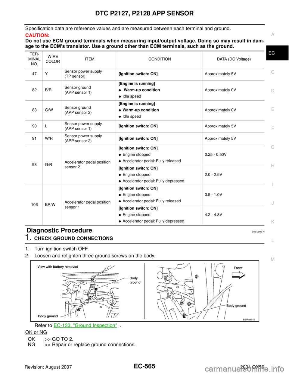
Specification data are reference values and are measured between each terminal and ground.
CAUTION:
Do not use ECM ground terminals when measuring input/output voltage. Doing so may result in dam-
age to the ECM's transistor. Use a ground other than ECM terminals, such as the ground.
Diagnostic ProcedureUBS00HCH
1. CHECK GROUND CONNECTIONS
1. Turn ignition switch OFF.
2. Loosen and retighten three ground screws on the body.
Refer to EC-133, "
Ground Inspection" .
OK or NG
OK >> GO TO 2.
NG >> Repair or replace ground connections.
TER-
MINAL
NO.WIRE
COLORITEM CONDITION DATA (DC Voltage)
47 YSensor power supply
(TP sensor)[Ignition switch: ON]Approximately 5V
82 B/RSensor ground
(APP sensor 1)[Engine is running]
� Warm-up condition
�Idle speedApproximately 0V
83 G/WSensor ground
(APP sensor 2)[Engine is running]
�Warm-up condition
�Idle speed Approximately 0V
90 LSensor power supply
(APP sensor 1)[Ignition switch: ON]Approximately 5V
91 W/RSensor power supply
(APP sensor 2)[Ignition switch: ON]Approximately 5V
98 G/RAccelerator pedal position
sensor 2[Ignition switch: ON]
�Engine stopped
�Accelerator pedal: Fully released0.25 - 0.50V
[Ignition switch: ON]
�Engine stopped
�Accelerator pedal: Fully depressed2.0 - 2.5V
106 BR/WAccelerator pedal position
sensor 1[Ignition switch: ON]
�Engine stopped
�Accelerator pedal: Fully released0.5 - 1.0V
[Ignition switch: ON]
�Engine stopped
�Accelerator pedal: Fully depressed4.2 - 4.8V
BBIA0354E
Page 1763 of 3371
EC-572Revision: August 2007
DTC P2135 TP SENSOR
2004 QX56
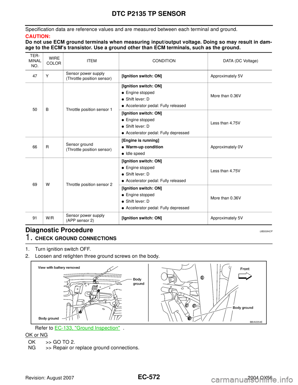
Specification data are reference values and are measured between each terminal and ground.
CAUTION:
Do not use ECM ground terminals when measuring input/output voltage. Doing so may result in dam-
age to the ECM's transistor. Use a ground other than ECM terminals, such as the ground.
Diagnostic ProcedureUBS00HCP
1. CHECK GROUND CONNECTIONS
1. Turn ignition switch OFF.
2. Loosen and retighten three ground screws on the body.
Refer to EC-133, "
Ground Inspection" .
OK or NG
OK >> GO TO 2.
NG >> Repair or replace ground connections.
TER-
MINAL
NO. WIRE
COLORITEM CONDITION DATA (DC Voltage)
47 YSensor power supply
(Throttle position sensor)[Ignition switch: ON]Approximately 5V
50 B Throttle position sensor 1[Ignition switch: ON]
�Engine stopped
�Shift lever: D
�Accelerator pedal: Fully releasedMore than 0.36V
[Ignition switch: ON]
�Engine stopped
�Shift lever: D
�Accelerator pedal: Fully depressedLess than 4.75V
66 RSensor ground
(Throttle position sensor)[Engine is running]
�Warm-up condition
�Idle speedApproximately 0V
69 W Throttle position sensor 2[Ignition switch: ON]
�Engine stopped
�Shift lever: D
�Accelerator pedal: Fully releasedLess than 4.75V
[Ignition switch: ON]
�Engine stopped
�Shift lever: D
�Accelerator pedal: Fully depressedMore than 0.36V
91 W/RSensor power supply
(APP sensor 2)[Ignition switch: ON]Approximately 5V
BBIA0354E
Page 1770 of 3371
DTC P2138 APP SENSOR
EC-579
C
D
E
F
G
H
I
J
K
L
MA
EC
Revision: August 20072004 QX56
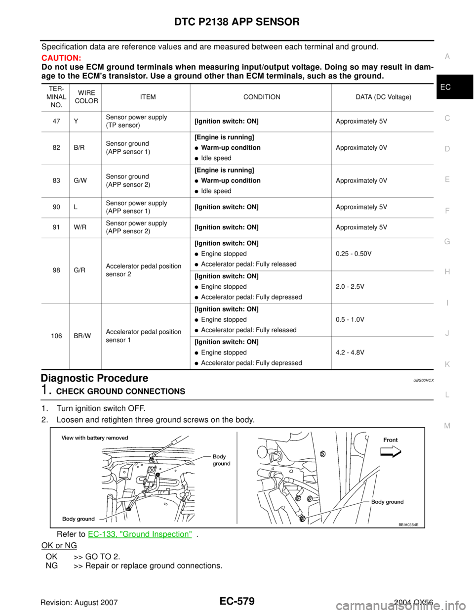
Specification data are reference values and are measured between each terminal and ground.
CAUTION:
Do not use ECM ground terminals when measuring input/output voltage. Doing so may result in dam-
age to the ECM's transistor. Use a ground other than ECM terminals, such as the ground.
Diagnostic ProcedureUBS00HCX
1. CHECK GROUND CONNECTIONS
1. Turn ignition switch OFF.
2. Loosen and retighten three ground screws on the body.
Refer to EC-133, "
Ground Inspection" .
OK or NG
OK >> GO TO 2.
NG >> Repair or replace ground connections.
TER-
MINAL
NO.WIRE
COLOR ITEM CONDITION DATA (DC Voltage)
47 YSensor power supply
(TP sensor)[Ignition switch: ON]Approximately 5V
82 B/RSensor ground
(APP sensor 1)[Engine is running]
�Warm-up condition
�Idle speedApproximately 0V
83 G/WSensor ground
(APP sensor 2)[Engine is running]
�Warm-up condition
�Idle speedApproximately 0V
90 LSensor power supply
(APP sensor 1)[Ignition switch: ON]Approximately 5V
91 W/RSensor power supply
(APP sensor 2)[Ignition switch: ON]Approximately 5V
98 G/RAccelerator pedal position
sensor 2[Ignition switch: ON]
�Engine stopped
�Accelerator pedal: Fully released0.25 - 0.50V
[Ignition switch: ON]
�Engine stopped
�Accelerator pedal: Fully depressed2.0 - 2.5V
106 BR/WAccelerator pedal position
sensor 1[Ignition switch: ON]
�Engine stopped
�Accelerator pedal: Fully released0.5 - 1.0V
[Ignition switch: ON]
�Engine stopped
�Accelerator pedal: Fully depressed4.2 - 4.8V
BBIA0354E
Page 1780 of 3371
IGNITION SIGNAL
EC-589
C
D
E
F
G
H
I
J
K
L
MA
EC
Revision: August 20072004 QX56
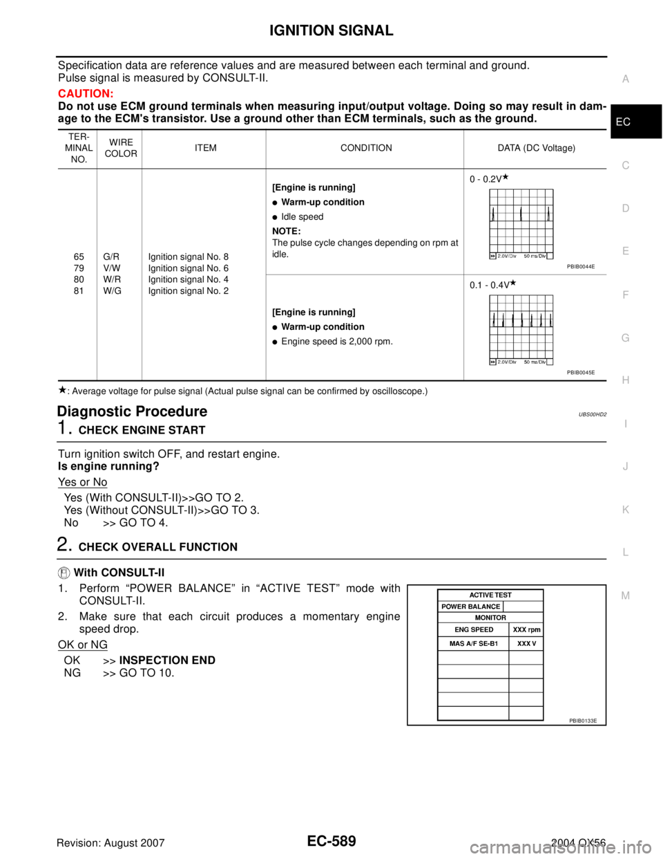
Specification data are reference values and are measured between each terminal and ground.
Pulse signal is measured by CONSULT-II.
CAUTION:
Do not use ECM ground terminals when measuring input/output voltage. Doing so may result in dam-
age to the ECM's transistor. Use a ground other than ECM terminals, such as the ground.
: Average voltage for pulse signal (Actual pulse signal can be confirmed by oscilloscope.)
Diagnostic ProcedureUBS00HD2
1. CHECK ENGINE START
Turn ignition switch OFF, and restart engine.
Is engine running?
Ye s o r N o
Yes (With CONSULT-II)>>GO TO 2.
Yes (Without CONSULT-II)>>GO TO 3.
No >> GO TO 4.
2. CHECK OVERALL FUNCTION
With CONSULT-II
1. Perform “POWER BALANCE” in “ACTIVE TEST” mode with
CONSULT-II.
2. Make sure that each circuit produces a momentary engine
speed drop.
OK or NG
OK >>INSPECTION END
NG >> GO TO 10.
TER-
MINAL
NO.WIRE
COLORITEM CONDITION DATA (DC Voltage)
65
79
80
81G/R
V/W
W/R
W/GIgnition signal No. 8
Ignition signal No. 6
Ignition signal No. 4
Ignition signal No. 2[Engine is running]
�Warm-up condition
�Idle speed
NOTE:
The pulse cycle changes depending on rpm at
idle.0 - 0.2V
[Engine is running]
�Warm-up condition
�Engine speed is 2,000 rpm.0.1 - 0.4V
PBIB0044E
PBIB0045E
PBIB0133E
Page 1781 of 3371
EC-590Revision: August 2007
IGNITION SIGNAL
2004 QX56
3. CHECK OVERALL FUNCTION
Without CONSULT-II
1. Let engine idle.
2. Read the voltage signal between ECM terminals 46, 60, 61, 62,
65, 79, 80, 81 and ground with an oscilloscope.
3. Verify that the oscilloscope screen shows the signal wave as
shown below.
NOTE:
The pulse cycle changes depending on rpm at idle.
OK or NG
OK >>INSPECTION END
NG >> GO TO 10.
4. CHECK IGNITION COIL POWER SUPPLY CIRCUIT-I
1. Turn ignition switch OFF, wait at least 10 seconds and then turn ON.
2. Check voltage between ECM terminals 119, 120 and ground
with CONSULT-II or tester.
OK or NG
OK >> GO TO 5.
NG >> Go to EC-128, "
POWER SUPPLY AND GROUND CIR-
CUIT" .
PBIB2094E
PBIB0044E
Voltage: Battery voltage
MBIB0034E
Page 1783 of 3371
EC-592Revision: August 2007
IGNITION SIGNAL
2004 QX56
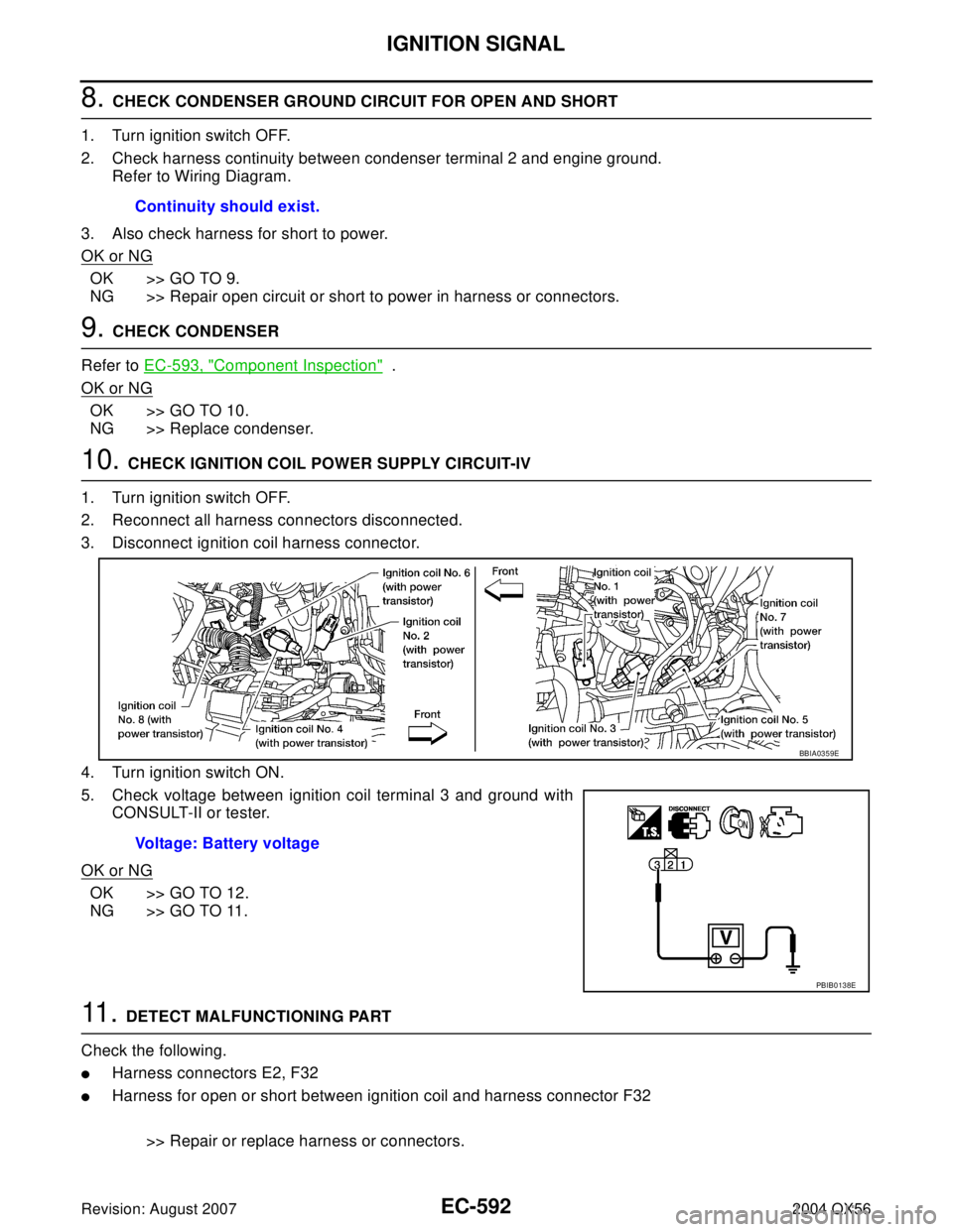
8. CHECK CONDENSER GROUND CIRCUIT FOR OPEN AND SHORT
1. Turn ignition switch OFF.
2. Check harness continuity between condenser terminal 2 and engine ground.
Refer to Wiring Diagram.
3. Also check harness for short to power.
OK or NG
OK >> GO TO 9.
NG >> Repair open circuit or short to power in harness or connectors.
9. CHECK CONDENSER
Refer to EC-593, "
Component Inspection" .
OK or NG
OK >> GO TO 10.
NG >> Replace condenser.
10. CHECK IGNITION COIL POWER SUPPLY CIRCUIT-IV
1. Turn ignition switch OFF.
2. Reconnect all harness connectors disconnected.
3. Disconnect ignition coil harness connector.
4. Turn ignition switch ON.
5. Check voltage between ignition coil terminal 3 and ground with
CONSULT-II or tester.
OK or NG
OK >> GO TO 12.
NG >> GO TO 11.
11 . DETECT MALFUNCTIONING PART
Check the following.
�Harness connectors E2, F32
�Harness for open or short between ignition coil and harness connector F32
>> Repair or replace harness or connectors. Continuity should exist.
Voltage: Battery voltage
BBIA0359E
PBIB0138E
Page 1784 of 3371
IGNITION SIGNAL
EC-593
C
D
E
F
G
H
I
J
K
L
MA
EC
Revision: August 20072004 QX56
12. CHECK IGNITION COIL GROUND CIRCUIT FOR OPEN AND SHORT
1. Turn ignition switch OFF.
2. Check harness continuity between ignition coil terminal 2 and engine ground.
Refer to Wiring Diagram.
3. Also check harness for short to power.
OK or NG
OK >> GO TO 13.
NG >> Repair open circuit or short to power in harness or connectors.
13. CHECK IGNITION COIL OUTPUT SIGNAL CIRCUIT FOR OPEN AND SHORT
1. Disconnect ECM harness connector.
2. Check harness continuity between ECM terminals 46, 60, 61, 62, 65, 79, 80, 81 and ignition coil terminal
1.
Refer to Wiring Diagram.
3. Also check harness for short to ground and short to power.
OK or NG
OK >> GO TO 14.
NG >> Repair open circuit or short to ground or short to power in harness or connectors.
14. CHECK IGNITION COIL WITH POWER TRANSISTOR
Refer to EC-593, "
Component Inspection" .
OK or NG
OK >> GO TO 15.
NG >> Replace ignition coil with power transistor.
15. CHECK INTERMITTENT INCIDENT
Refer to EC-127, "
TROUBLE DIAGNOSIS FOR INTERMITTENT INCIDENT" .
>>INSPECTION END
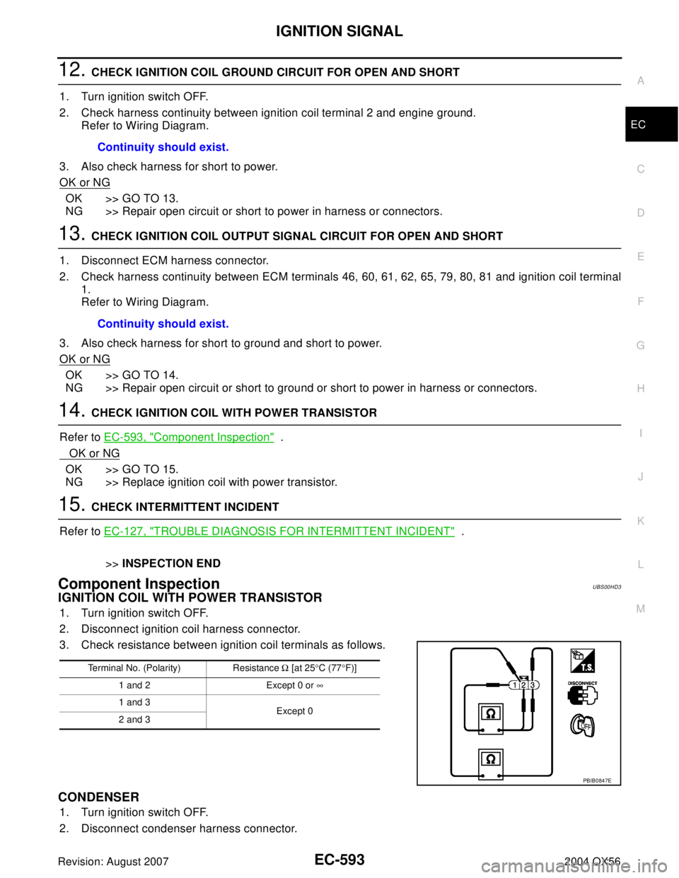
Component InspectionUBS00HD3
IGNITION COIL WITH POWER TRANSISTOR
1. Turn ignition switch OFF.
2. Disconnect ignition coil harness connector.
3. Check resistance between ignition coil terminals as follows.
CONDENSER
1. Turn ignition switch OFF.
2. Disconnect condenser harness connector.Continuity should exist.
Continuity should exist.
Terminal No. (Polarity) Resistance Ω [at 25°C (77°F)]
1 and 2 Except 0 or ∞
1 and 3
Except 0
2 and 3
PBIB0847E
Page 1789 of 3371
EC-598Revision: August 2007
INJECTOR CIRCUIT
2004 QX56
2. CHECK OVERALL FUNCTION
With CONSULT-II
1. Start engine.
2. Perform “POWER BALANCE” in “ACTIVE TEST” mode with
CONSULT-II.
3. Make sure that each circuit produces a momentary engine
speed drop.
Without CONSULT-II
1. Start engine.
2. Listen to each injector operating sound.
Clicking noise should be heard.
OK or NG
OK >>INSPECTION END
NG >> GO TO 3.
PBIB0133E
PBIB1986E