2004 INFINITI QX56 fuel
[x] Cancel search: fuelPage 1127 of 3371
DI-24
COMBINATION METERS
Revision: August 20072004 QX56
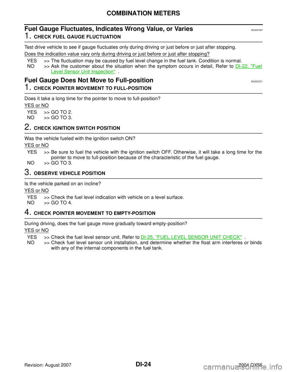
Fuel Gauge Fluctuates, Indicates Wrong Value, or VariesEKS007E0
1. CHECK FUEL GAUGE FLUCTUATION
Test drive vehicle to see if gauge fluctuates only during driving or just before or just after stopping.
Does the indication value vary only during driving or just before or just after stopping?
YES >> The fluctuation may be caused by fuel level change in the fuel tank. Condition is normal.
NO >> Ask the customer about the situation when the symptom occurs in detail, Refer to DI-22, "
Fuel
Level Sensor Unit Inspection" .
Fuel Gauge Does Not Move to Full-positionEKS007E1
1. CHECK POINTER MOVEMENT TO FULL-POSITION
Does it take a long time for the pointer to move to full-position?
YES or NO
YES >> GO TO 2.
NO >> GO TO 3.
2. CHECK IGNITION SWITCH POSITION
Was the vehicle fueled with the ignition switch ON?
YES or NO
YES >> Be sure to fuel the vehicle with the ignition switch OFF. Otherwise, it will take a long time for the
pointer to move to full-position because of the characteristic of the fuel gauge.
NO >> GO TO 3.
3. OBSERVE VEHICLE POSITION
Is the vehicle parked on an incline?
YES or NO
YES >> Check the fuel level indication with vehicle on a level surface.
NO >> GO TO 4.
4. CHECK POINTER MOVEMENT TO EMPTY-POSITION
During driving, does the fuel gauge move gradually toward empty-position?
YES or NO
YES >> Check the fuel level sensor unit. Refer to DI-25, "FUEL LEVEL SENSOR UNIT CHECK" .
NO >> Check fuel level sensor unit installation, and determine whether the float arm interferes or binds
with any of the internal components in the fuel tank.
Page 1128 of 3371
COMBINATION METERS
DI-25
C
D
E
F
G
H
I
J
L
MA
B
DI
Revision: August 20072004 QX56
Electrical Components InspectionEKS007E2
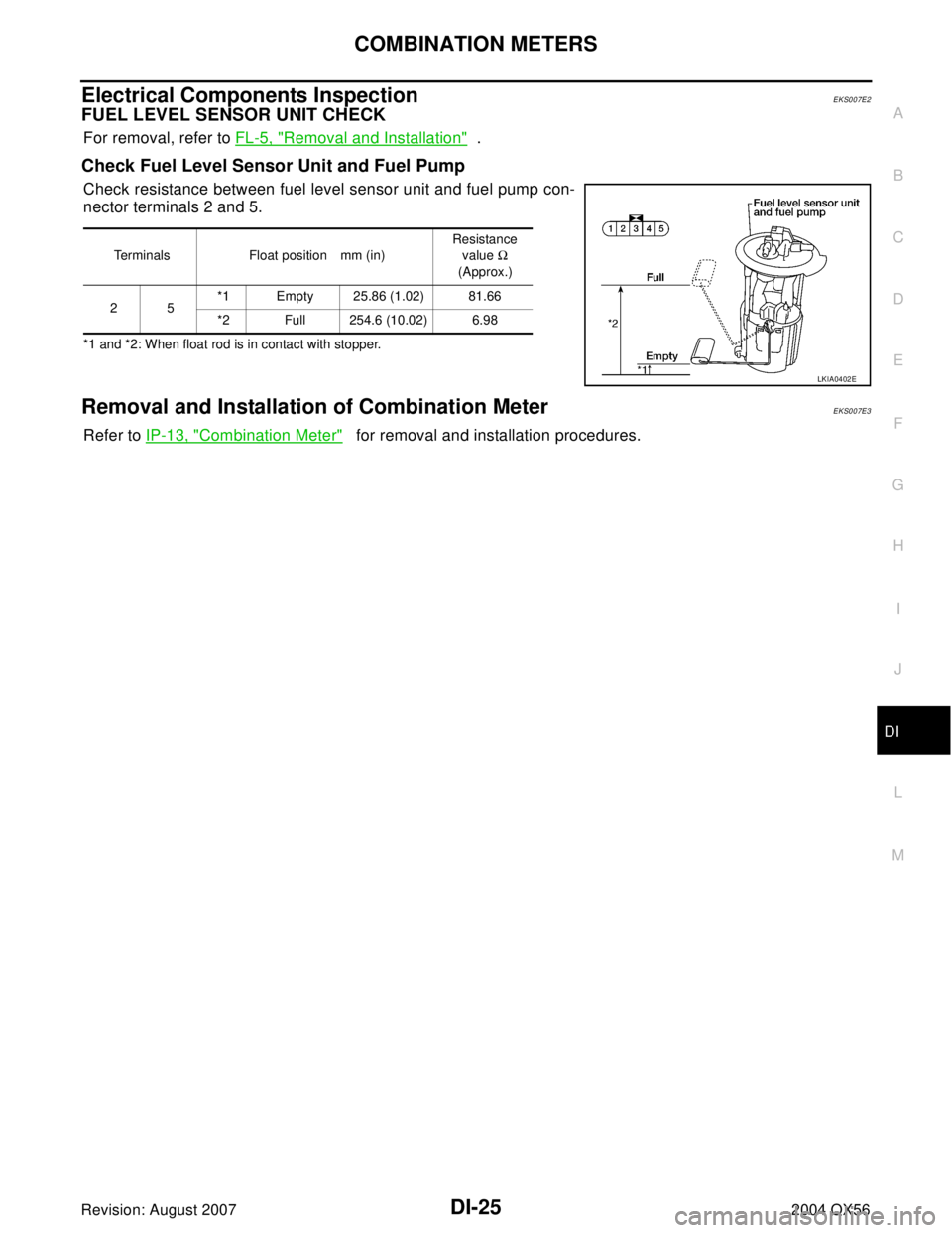
FUEL LEVEL SENSOR UNIT CHECK
For removal, refer to FL-5, "Removal and Installation" .
Check Fuel Level Sensor Unit and Fuel Pump
Check resistance between fuel level sensor unit and fuel pump con-
nector terminals 2 and 5.
*1 and *2: When float rod is in contact with stopper.
Removal and Installation of Combination MeterEKS007E3
Refer to IP-13, "Combination Meter" for removal and installation procedures.
Terminals Float position mm (in)Resistance
value Ω
(Approx.)
25*1 Empty 25.86 (1.02) 81.66
*2 Full 254.6 (10.02) 6.98
LKIA0402E
Page 1192 of 3371
EC-1
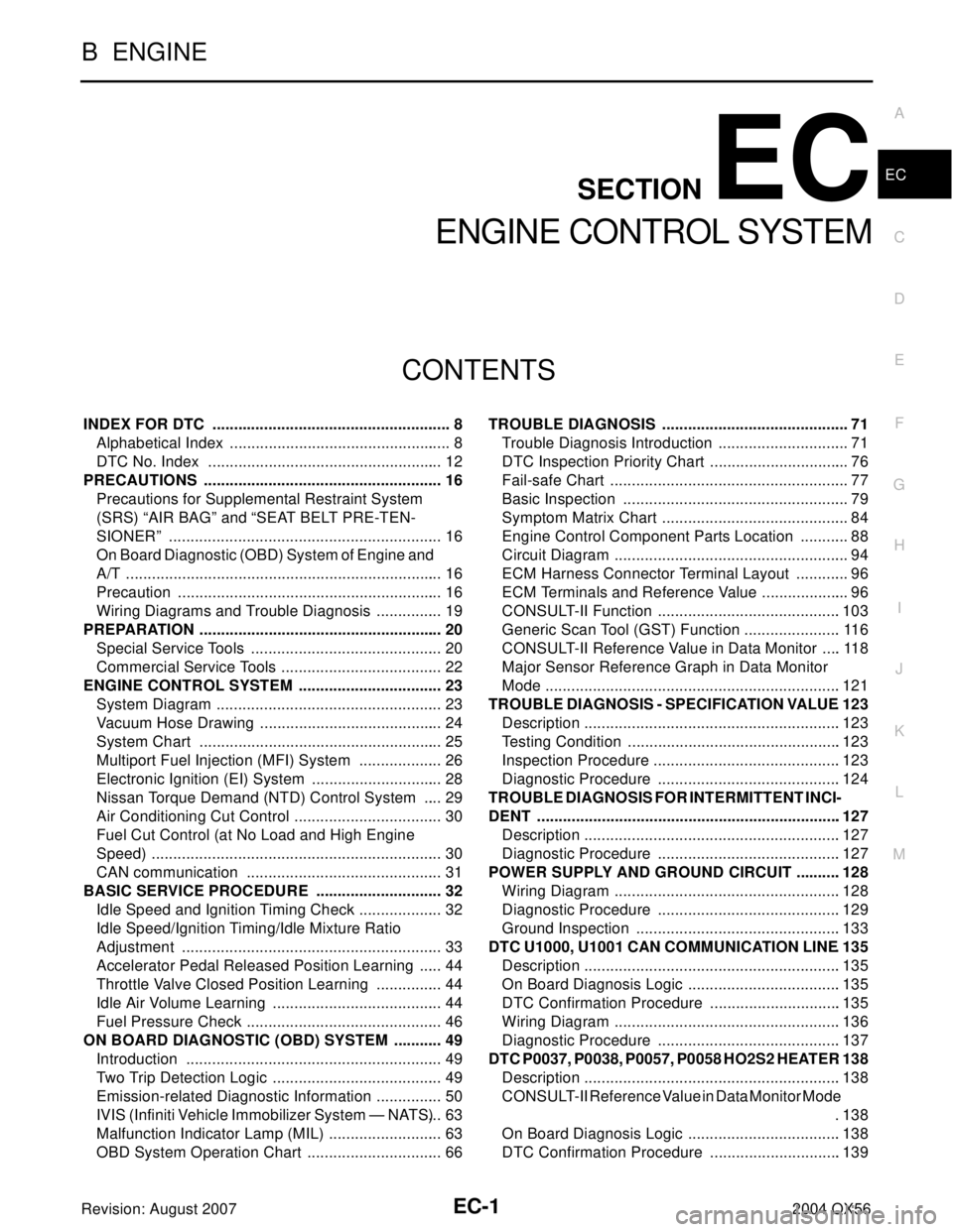
ENGINE CONTROL SYSTEM
B ENGINE
CONTENTS
C
D
E
F
G
H
I
J
K
L
M
SECTION EC
A
EC
Revision: August 20072004 QX56 INDEX FOR DTC ........................................................ 8
Alphabetical Index .................................................... 8
DTC No. Index ....................................................... 12
PRECAUTIONS ........................................................ 16
Precautions for Supplemental Restraint System
(SRS) “AIR BAG” and “SEAT BELT PRE-TEN-
SIONER” ................................................................ 16
On Board Diagnostic (OBD) System of Engine and
A/T .......................................................................... 16
Precaution .............................................................. 16
Wiring Diagrams and Trouble Diagnosis ................ 19
PREPARATION ......................................................... 20
Special Service Tools ............................................. 20
Commercial Service Tools ...................................... 22
ENGINE CONTROL SYSTEM .................................. 23
System Diagram ..................................................... 23
Vacuum Hose Drawing ........................................... 24
System Chart ......................................................... 25
Multiport Fuel Injection (MFI) System .................... 26
Electronic Ignition (EI) System ............................... 28
Nissan Torque Demand (NTD) Control System ..... 29
Air Conditioning Cut Control ................................... 30
Fuel Cut Control (at No Load and High Engine
Speed) .................................................................... 30
CAN communication .............................................. 31
BASIC SERVICE PROCEDURE .............................. 32
Idle Speed and Ignition Timing Check .................... 32
Idle Speed/Ignition Timing/Idle Mixture Ratio
Adjustment ............................................................. 33
Accelerator Pedal Released Position Learning ...... 44
Throttle Valve Closed Position Learning ................ 44
Idle Air Volume Learning ........................................ 44
Fuel Pressure Check .............................................. 46
ON BOARD DIAGNOSTIC (OBD) SYSTEM ............ 49
Introduction ............................................................ 49
Two Trip Detection Logic ........................................ 49
Emission-related Diagnostic Information ................ 50
IVIS (Infiniti Vehicle Immobilizer System — NATS) ... 63
Malfunction Indicator Lamp (MIL) ........................... 63
OBD System Operation Chart ................................ 66TROUBLE DIAGNOSIS ............................................ 71
Trouble Diagnosis Introduction ............................... 71
DTC Inspection Priority Chart ................................. 76
Fail-safe Chart ........................................................ 77
Basic Inspection ..................................................... 79
Symptom Matrix Chart ............................................ 84
Engine Control Component Parts Location ............ 88
Circuit Diagram ....................................................... 94
ECM Harness Connector Terminal Layout ............. 96
ECM Terminals and Reference Value ..................... 96
CONSULT-II Function ...........................................103
Generic Scan Tool (GST) Function .......................116
CONSULT-II Reference Value in Data Monitor .....118
Major Sensor Reference Graph in Data Monitor
Mode .....................................................................121
TROUBLE DIAGNOSIS - SPECIFICATION VALUE .123
Description ............................................................123
Testing Condition ..................................................123
Inspection Procedure ............................................123
Diagnostic Procedure ...........................................124
TROUBLE DIAGNOSIS FOR INTERMITTENT INCI-
DENT .......................................................................127
Description ............................................................127
Diagnostic Procedure ...........................................127
POWER SUPPLY AND GROUND CIRCUIT ...........128
Wiring Diagram .....................................................128
Diagnostic Procedure ...........................................129
Ground Inspection ................................................133
DTC U1000, U1001 CAN COMMUNICATION LINE .135
Description ............................................................135
On Board Diagnosis Logic ....................................135
DTC Confirmation Procedure ...............................135
Wiring Diagram .....................................................136
Diagnostic Procedure ...........................................137
DTC P0037, P0038, P0057, P0058 HO2S2 HEATER .138
Description ............................................................138
CONSULT-II Reference Value in Data Monitor Mode
.138
On Board Diagnosis Logic ....................................138
DTC Confirmation Procedure ...............................139
Page 1193 of 3371

EC-2Revision: August 20072004 QX56 Wiring Diagram .....................................................140
Diagnostic Procedure ...........................................143
Component Inspection ..........................................145
Removal and Installation ......................................145
DTC P0101 MAF SENSOR .....................................146
Component Description ........................................146
CONSULT-II Reference Value in Data Monitor Mode
.146
On Board Diagnosis Logic ....................................146
DTC Confirmation Procedure ...............................147
Overall Function Check ........................................148
Wiring Diagram .....................................................149
Diagnostic Procedure ...........................................150
Component Inspection ..........................................153
Removal and Installation ......................................153
DTC P0102, P0103 MAF SENSOR .........................154
Component Description ........................................154
CONSULT-II Reference Value in Data Monitor Mode
.154
On Board Diagnosis Logic ....................................154
DTC Confirmation Procedure ...............................155
Wiring Diagram .....................................................156
Diagnostic Procedure ...........................................157
Component Inspection ..........................................160
Removal and Installation ......................................160
DTC P0112, P0113 IAT SENSOR ...........................161
Component Description ........................................161
On Board Diagnosis Logic ....................................161
DTC Confirmation Procedure ...............................161
Wiring Diagram .....................................................162
Diagnostic Procedure ...........................................163
Component Inspection ..........................................164
Removal and Installation ......................................164
DTC P0117, P0118 ECT SENSOR ..........................165
Component Description ........................................165
On Board Diagnosis Logic ....................................165
DTC Confirmation Procedure ...............................166
Wiring Diagram .....................................................167
Diagnostic Procedure ...........................................168
Component Inspection ..........................................169
Removal and Installation ......................................170
DTC P0122, P0123 TP SENSOR ............................171
Component Description ........................................171
CONSULT-II Reference Value in Data Monitor Mode
.171
On Board Diagnosis Logic ....................................171
DTC Confirmation Procedure ...............................172
Wiring Diagram .....................................................173
Diagnostic Procedure ...........................................174
Component Inspection ..........................................177
Removal and Installation ......................................177
DTC P0125 ECT SENSOR ......................................178
Component Description ........................................178
On Board Diagnosis Logic ....................................178
DTC Confirmation Procedure ...............................179
Diagnostic Procedure ...........................................179
Component Inspection ..........................................180
Removal and Installation ......................................180
DTC P0127 IAT SENSOR .......................................181Component Description ........................................ 181
On Board Diagnosis Logic .................................... 181
DTC Confirmation Procedure ................................ 181
Diagnostic Procedure ............................................ 182
Component Inspection .......................................... 183
Removal and Installation ....................................... 183
DTC P0128 THERMOSTAT FUNCTION ................. 184
On Board Diagnosis Logic .................................... 184
DTC Confirmation Procedure ................................ 184
Diagnostic Procedure ............................................ 184
Component Inspection .......................................... 184
Removal and Installation ....................................... 185
DTC P0138, P0158 HO2S2 ..................................... 186
Component Description ........................................ 186
CONSULT-II Reference Value in Data Monitor Mode
. 186
On Board Diagnosis Logic .................................... 186
DTC Confirmation Procedure ................................ 187
Wiring Diagram ..................................................... 188
Diagnostic Procedure ............................................ 191
Component Inspection .......................................... 194
Removal and Installation ....................................... 195
DTC P0139, P0159 HO2S2 ..................................... 196
Component Description ........................................ 196
CONSULT-II Reference Value in Data Monitor Mode
. 196
On Board Diagnosis Logic .................................... 196
DTC Confirmation Procedure ................................ 197
Overall Function Check ......................................... 197
Wiring Diagram ..................................................... 199
Diagnostic Procedure ............................................ 202
Component Inspection .......................................... 205
Removal and Installation ....................................... 207
DTC P0171, P0174 FUEL INJECTION SYSTEM
FUNCTION .............................................................. 208
On Board Diagnosis Logic .................................... 208
DTC Confirmation Procedure ................................ 208
Wiring Diagram ..................................................... 210
Diagnostic Procedure ............................................ 212
DTC P0172, P0175 FUEL INJECTION SYSTEM
FUNCTION .............................................................. 217
On Board Diagnosis Logic .................................... 217
DTC Confirmation Procedure ................................ 217
Wiring Diagram ..................................................... 219
Diagnostic Procedure ............................................ 221
DTC P0181 FTT SENSOR ...................................... 225
Component Description ........................................ 225
On Board Diagnosis Logic .................................... 225
DTC Confirmation Procedure ................................ 225
Wiring Diagram ..................................................... 227
Diagnostic Procedure ............................................ 228
Component Inspection .......................................... 229
Removal and Installation ....................................... 230
DTC P0182, P0183 FTT SENSOR .......................... 231
Component Description ........................................ 231
On Board Diagnosis Logic .................................... 231
DTC Confirmation Procedure ................................ 231
Wiring Diagram ..................................................... 232
Diagnostic Procedure ............................................ 233
Page 1195 of 3371

EC-4Revision: August 20072004 QX56 Overall Function Check ........................................326
Diagnostic Procedure ...........................................327
DTC P0460 FUEL LEVEL SENSOR .......................334
Component Description ........................................334
On Board Diagnosis Logic ....................................334
DTC Confirmation Procedure ...............................334
Diagnostic Procedure ...........................................335
Removal and Installation ......................................335
DTC P0461 FUEL LEVEL SENSOR .......................336
Component Description ........................................336
On Board Diagnosis Logic ....................................336
Overall Function Check ........................................336
Diagnostic Procedure ...........................................337
Removal and Installation ......................................337
DTC P0462, P0463 FUEL LEVEL SENSOR CIR-
CUIT ........................................................................338
Component Description ........................................338
On Board Diagnosis Logic ....................................338
DTC Confirmation Procedure ...............................338
Diagnostic Procedure ...........................................339
Removal and Installation ......................................339
DTC P0500 VSS ......................................................340
Description ............................................................340
On Board Diagnosis Logic ....................................340
DTC Confirmation Procedure ...............................340
Overall Function Check ........................................340
Diagnostic Procedure ...........................................341
DTC P0506 ISC SYSTEM .......................................342
Description ............................................................342
On Board Diagnosis Logic ....................................342
DTC Confirmation Procedure ...............................342
Diagnostic Procedure ...........................................343
DTC P0507 ISC SYSTEM .......................................344
Description ............................................................344
On Board Diagnosis Logic ....................................344
DTC Confirmation Procedure ...............................344
Diagnostic Procedure ...........................................345
DTC P0550 PSP SENSOR ......................................346
Component Description ........................................346
CONSULT-II Reference Value in Data Monitor Mode
.346
On Board Diagnosis Logic ....................................346
DTC Confirmation Procedure ...............................346
Wiring Diagram .....................................................347
Diagnostic Procedure ...........................................348
Component Inspection ..........................................350
Removal and Installation ......................................350
DTC P0605 ECM .....................................................351
Component Description ........................................351
On Board Diagnosis Logic ....................................351
DTC Confirmation Procedure ...............................351
Diagnostic Procedure ...........................................352
DTC P1031, P1032, P1051, P1052 A/F SENSOR 1
HEATER ..................................................................354
Description ............................................................354
CONSULT-II Reference Value in Data Monitor Mode
.354
On Board Diagnosis Logic ....................................354
DTC Confirmation Procedure ...............................354Wiring Diagram ..................................................... 355
Diagnostic Procedure ............................................ 358
Component Inspection .......................................... 360
Removal and Installation ....................................... 360
DTC P1065 ECM POWER SUPPLY ........................ 361
Component Description ........................................ 361
On Board Diagnosis Logic .................................... 361
DTC Confirmation Procedure ................................ 361
Wiring Diagram ..................................................... 362
Diagnostic Procedure ............................................ 363
DTC P1121 ELECTRIC THROTTLE CONTROL
ACTUATOR ............................................................. 365
Component Description ........................................ 365
On Board Diagnosis Logic .................................... 365
DTC Confirmation Procedure ................................ 365
Diagnostic Procedure ............................................ 366
DTC P1122 ELECTRIC THROTTLE CONTROL
FUNCTION .............................................................. 367
Description ............................................................ 367
On Board Diagnosis Logic .................................... 367
DTC Confirmation Procedure ................................ 367
Wiring Diagram ..................................................... 368
Diagnostic Procedure ............................................ 369
Component Inspection .......................................... 372
Remove and Installation ....................................... 372
DTC P1124, P1126 THROTTLE CONTROL MOTOR
RELAY ..................................................................... 373
Component Description ........................................ 373
CONSULT-II Reference Value in Data Monitor Mode
. 373
On Board Diagnosis Logic .................................... 373
DTC Confirmation Procedure ................................ 373
Wiring Diagram ..................................................... 375
Diagnostic Procedure ............................................ 376
DTC P1128 THROTTLE CONTROL MOTOR ......... 378
Component Description ........................................ 378
On Board Diagnosis Logic .................................... 378
DTC Confirmation Procedure ................................ 378
Wiring Diagram ..................................................... 379
Diagnostic Procedure ............................................ 380
Component Inspection .......................................... 381
Removal and Installation ....................................... 382
DTC P1146, P1166 HO2S2 ..................................... 383
Component Description ........................................ 383
CONSULT-II Reference Value in Data Monitor Mode
. 383
On Board Diagnosis Logic .................................... 383
DTC Confirmation Procedure ................................ 384
Overall Function Check ......................................... 384
Wiring Diagram ..................................................... 386
Diagnostic Procedure ............................................ 389
Component Inspection .......................................... 392
Removal and Installation ....................................... 394
DTC P1147, P1167 HO2S2 ..................................... 395
Component Description ........................................ 395
CONSULT-II Reference Value in Data Monitor Mode
. 395
On Board Diagnosis Logic .................................... 395
DTC Confirmation Procedure ................................ 396
Page 1198 of 3371
EC-7
C
D
E
F
G
H
I
J
K
L
M
ECA
Revision: August 20072004 QX56 Component Inspection ......................................... 582
Removal and Installation ...................................... 582
IGNITION SIGNAL .................................................. 583
Component Description ........................................ 583
Wiring Diagram .................................................... 584
Diagnostic Procedure ........................................... 589
Component Inspection ......................................... 593
Removal and Installation ...................................... 594
INJECTOR CIRCUIT ............................................... 595
Component Description ........................................ 595
CONSULT-II Reference Value in Data Monitor Mode
. 595
Wiring Diagram .................................................... 596
Diagnostic Procedure ........................................... 597
Component Inspection ......................................... 600
Removal and Installation ...................................... 600
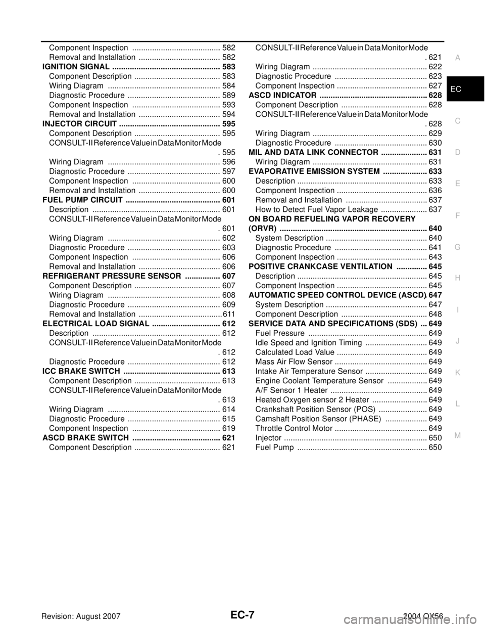
FUEL PUMP CIRCUIT ............................................ 601
Description ........................................................... 601
CONSULT-II Reference Value in Data Monitor Mode
. 601
Wiring Diagram .................................................... 602
Diagnostic Procedure ........................................... 603
Component Inspection ......................................... 606
Removal and Installation ...................................... 606
REFRIGERANT PRESSURE SENSOR ................. 607
Component Description ........................................ 607
Wiring Diagram .................................................... 608
Diagnostic Procedure ........................................... 609
Removal and Installation ....................................... 611
ELECTRICAL LOAD SIGNAL ................................ 612
Description ........................................................... 612
CONSULT-II Reference Value in Data Monitor Mode
. 612
Diagnostic Procedure ........................................... 612
ICC BRAKE SWITCH ............................................. 613
Component Description ........................................ 613
CONSULT-II Reference Value in Data Monitor Mode
. 613
Wiring Diagram .................................................... 614
Diagnostic Procedure ........................................... 615
Component Inspection ......................................... 619
ASCD BRAKE SWITCH ......................................... 621
Component Description ........................................ 621CONSULT-II Reference Value in Data Monitor Mode
.621
Wiring Diagram .....................................................622
Diagnostic Procedure ...........................................623
Component Inspection ..........................................627
ASCD INDICATOR ..................................................628
Component Description ........................................628
CONSULT-II Reference Value in Data Monitor Mode
.628
Wiring Diagram .....................................................629
Diagnostic Procedure ...........................................630
MIL AND DATA LINK CONNECTOR ......................631
Wiring Diagram .....................................................631
EVAPORATIVE EMISSION SYSTEM .....................633
Description ............................................................633
Component Inspection ..........................................636
Removal and Installation ......................................637
How to Detect Fuel Vapor Leakage ......................637
ON BOARD REFUELING VAPOR RECOVERY
(ORVR) ....................................................................640
System Description ...............................................640
Diagnostic Procedure ...........................................641
Component Inspection ..........................................643
POSITIVE CRANKCASE VENTILATION ...............645
Description ............................................................645
Component Inspection ..........................................645
AUTOMATIC SPEED CONTROL DEVICE (ASCD) .647
System Description ...............................................647
Component Description ........................................648
SERVICE DATA AND SPECIFICATIONS (SDS) ....649
Fuel Pressure .......................................................649
Idle Speed and Ignition Timing .............................649
Calculated Load Value ..........................................649
Mass Air Flow Sensor ...........................................649
Intake Air Temperature Sensor .............................649
Engine Coolant Temperature Sensor ...................649
A/F Sensor 1 Heater .............................................649
Heated Oxygen sensor 2 Heater ..........................649
Crankshaft Position Sensor (POS) .......................649
Camshaft Position Sensor (PHASE) ....................649
Throttle Control Motor ...........................................649
Injector ..................................................................650
Fuel Pump ............................................................650
Page 1200 of 3371
INDEX FOR DTC
EC-9
C
D
E
F
G
H
I
J
K
L
MA
EC
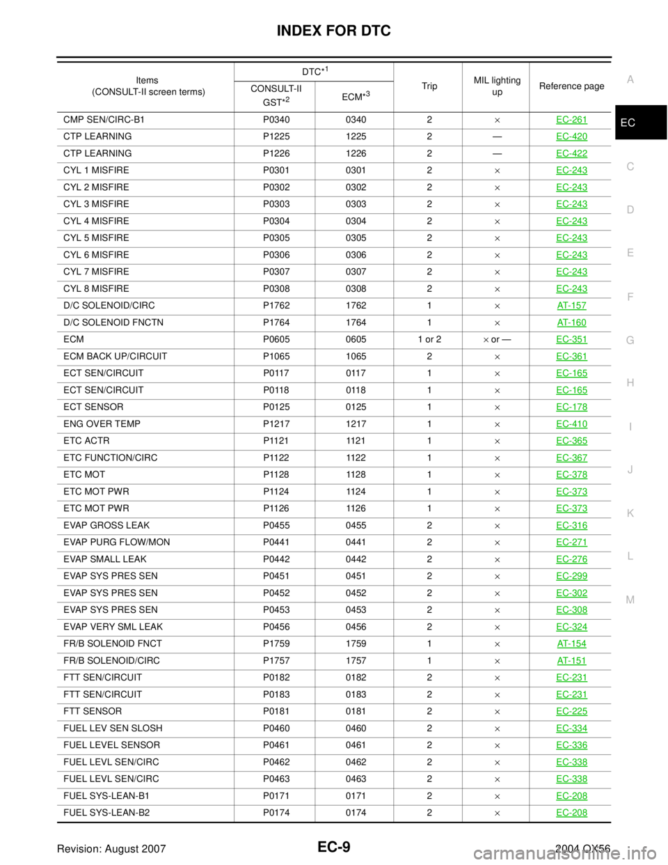
Revision: August 20072004 QX56CMP SEN/CIRC-B1 P0340 0340 2×EC-261
CTP LEARNING P1225 1225 2 —EC-420
CTP LEARNING P1226 1226 2 —EC-422
CYL 1 MISFIRE P0301 0301 2×EC-243
CYL 2 MISFIRE P0302 0302 2×EC-243
CYL 3 MISFIRE P0303 0303 2×EC-243
CYL 4 MISFIRE P0304 0304 2×EC-243
CYL 5 MISFIRE P0305 0305 2×EC-243
CYL 6 MISFIRE P0306 0306 2×EC-243
CYL 7 MISFIRE P0307 0307 2×EC-243
CYL 8 MISFIRE P0308 0308 2×EC-243
D/C SOLENOID/CIRC P1762 1762 1×AT- 1 5 7
D/C SOLENOID FNCTN P1764 1764 1×AT- 1 6 0
ECM P0605 0605 1 or 2× or —EC-351
ECM BACK UP/CIRCUIT P1065 1065 2×EC-361
ECT SEN/CIRCUIT P0117 0117 1×EC-165
ECT SEN/CIRCUIT P0118 0118 1×EC-165
ECT SENSOR P0125 0125 1×EC-178
ENG OVER TEMP P1217 1217 1×EC-410
ETC ACTR P1121 1121 1×EC-365
ETC FUNCTION/CIRC P1122 1122 1×EC-367
E T C M O T P 11 2 8 11 2 8 1×EC-378
E T C M O T P W R P 11 2 4 11 2 4 1×EC-373
E T C M O T P W R P 11 2 6 11 2 6 1×EC-373
EVAP GROSS LEAK P0455 0455 2×EC-316
EVAP PURG FLOW/MON P0441 0441 2×EC-271
EVAP SMALL LEAK P0442 0442 2×EC-276
EVAP SYS PRES SEN P0451 0451 2×EC-299
EVAP SYS PRES SEN P0452 0452 2×EC-302
EVAP SYS PRES SEN P0453 0453 2×EC-308
EVAP VERY SML LEAK P0456 0456 2×EC-324
FR/B SOLENOID FNCT P1759 1759 1×AT- 1 5 4
FR/B SOLENOID/CIRC P1757 1757 1×AT- 1 5 1
FTT SEN/CIRCUIT P0182 0182 2×EC-231
FTT SEN/CIRCUIT P0183 0183 2×EC-231
FTT SENSOR P0181 0181 2×EC-225
FUEL LEV SEN SLOSH P0460 0460 2×EC-334
FUEL LEVEL SENSOR P0461 0461 2×EC-336
FUEL LEVL SEN/CIRC P0462 0462 2×EC-338
FUEL LEVL SEN/CIRC P0463 0463 2×EC-338
FUEL SYS-LEAN-B1 P0171 0171 2×EC-208
FUEL SYS-LEAN-B2 P0174 0174 2×EC-208
Items
(CONSULT-II screen terms)DTC*
1
TripMIL lighting
upReference page
CONSULT-II
GST*
2ECM*3
Page 1201 of 3371
EC-10Revision: August 2007
INDEX FOR DTC
2004 QX56
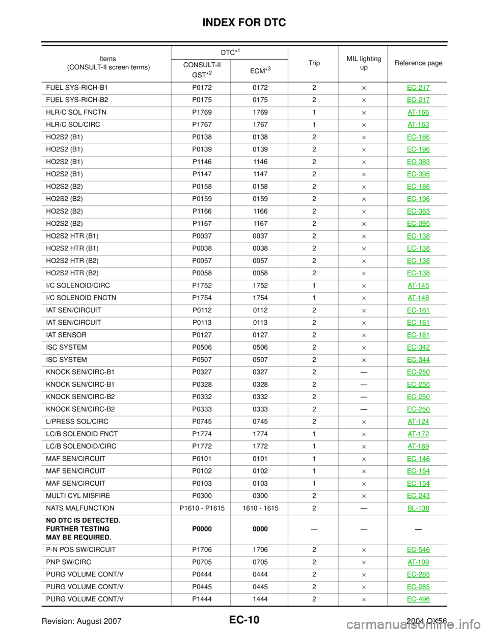
FUEL SYS-RICH-B1 P0172 0172 2×EC-217
FUEL SYS-RICH-B2 P0175 0175 2×EC-217
HLR/C SOL FNCTN P1769 1769 1×AT-166
HLR/C SOL/CIRC P1767 1767 1×AT-163
HO2S2 (B1) P0138 0138 2×EC-186
HO2S2 (B1) P0139 0139 2×EC-196
HO2S2 (B1) P1146 1146 2×EC-383
HO2S2 (B1) P1147 1147 2×EC-395
HO2S2 (B2) P0158 0158 2×EC-186
HO2S2 (B2) P0159 0159 2×EC-196
HO2S2 (B2) P1166 1166 2×EC-383
HO2S2 (B2) P1167 1167 2×EC-395
HO2S2 HTR (B1) P0037 0037 2×EC-138
HO2S2 HTR (B1) P0038 0038 2×EC-138
HO2S2 HTR (B2) P0057 0057 2×EC-138
HO2S2 HTR (B2) P0058 0058 2×EC-138
I/C SOLENOID/CIRC P1752 1752 1×AT-145
I/C SOLENOID FNCTN P1754 1754 1×AT-148
IAT SEN/CIRCUIT P0112 0112 2×EC-161
IAT SEN/CIRCUIT P0113 0113 2×EC-161
IAT SENSOR P0127 0127 2×EC-181
ISC SYSTEM P0506 0506 2×EC-342
ISC SYSTEM P0507 0507 2×EC-344
KNOCK SEN/CIRC-B1 P0327 0327 2 —EC-250
KNOCK SEN/CIRC-B1 P0328 0328 2 —EC-250
KNOCK SEN/CIRC-B2 P0332 0332 2 —EC-250
KNOCK SEN/CIRC-B2 P0333 0333 2 —EC-250
L/PRESS SOL/CIRC P0745 0745 2×AT-124
LC/B SOLENOID FNCT P1774 1774 1×AT-172
LC/B SOLENOID/CIRC P1772 1772 1×AT-169
MAF SEN/CIRCUIT P0101 0101 1×EC-146
MAF SEN/CIRCUIT P0102 0102 1×EC-154
MAF SEN/CIRCUIT P0103 0103 1×EC-154
MULTI CYL MISFIRE P0300 0300 2×EC-243
NATS MALFUNCTION P1610 - P1615 1610 - 1615 2 —BL-138
NO DTC IS DETECTED.
FURTHER TESTING
MAY BE REQUIRED.P0000 0000———
P-N POS SW/CIRCUIT P1706 1706 2×EC-546
PNP SW/CIRC P0705 0705 2×AT-109
PURG VOLUME CONT/V P0444 0444 2×EC-285
PURG VOLUME CONT/V P0445 0445 2×EC-285
PURG VOLUME CONT/V P1444 1444 2×EC-496
Items
(CONSULT-II screen terms)DTC*
1
TripMIL lighting
upReference page
CONSULT-II
GST*
2ECM*3