Page 2907 of 3371
RSU-48
SERVICE DATA AND SPECIFICATIONS (SDS)
Revision: August 20072004 QX56
Wheelarch Height (Unladen*1 )EES0011Z
Unit: mm (in)
*1: Fuel, engine coolant and engine oil full. Spare tire, jack, hand tools and mats in designated positions.
*2: Verify the vehicle height using Consult-II memory register 1103 and set rear wheelarch height to 0 ± 10 mm (0 ± 0.39 in) as neces-
sary.Suspension type
Air leveling*
2
Applied model4x2 4x4
Front wheelarch height (Hf)913
(35.94)931
(36.65)
Rear wheelarch height (Hr)912
(35.91)932
(36.69)
LEIA0085E
Page 2935 of 3371

SC-14
STARTING SYSTEM
Revision: August 20072004 QX56
DIAGNOSTIC PROCEDURE 1
Check Terminal "2" Circuit
1. CHECK POWER SUPPLY FOR STARTER MOTOR “2” TERMINAL
1. Remove the fuel pump fuse.
2. Crank or start the engine (where possible) until the fuel pressure is released.
3. Turn the ignition switch OFF.
4. Check that the starter motor connector F27 connection is clean and tight.
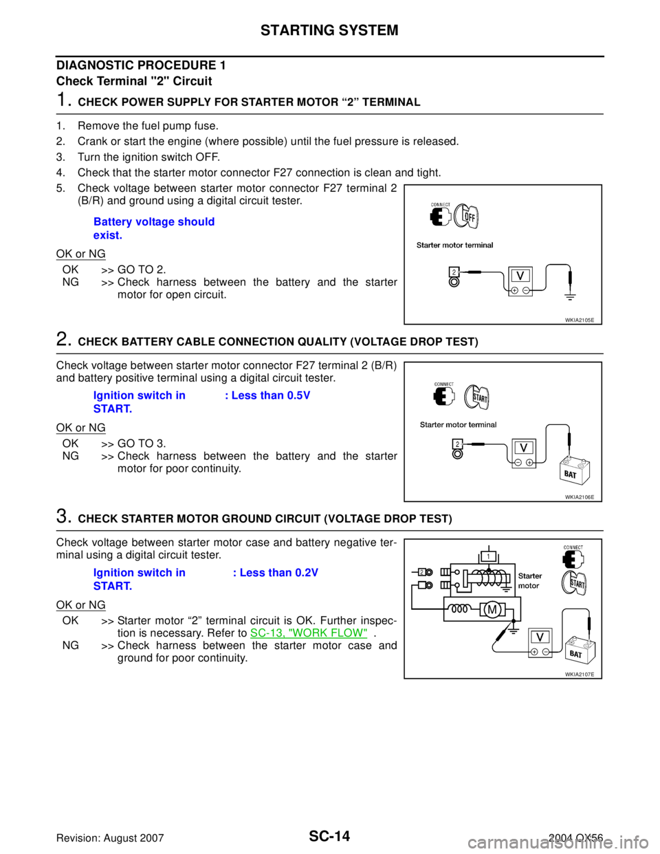
5. Check voltage between starter motor connector F27 terminal 2
(B/R) and ground using a digital circuit tester.
OK or NG
OK >> GO TO 2.
NG >> Check harness between the battery and the starter
motor for open circuit.
2. CHECK BATTERY CABLE CONNECTION QUALITY (VOLTAGE DROP TEST)
Check voltage between starter motor connector F27 terminal 2 (B/R)
and battery positive terminal using a digital circuit tester.
OK or NG
OK >> GO TO 3.
NG >> Check harness between the battery and the starter
motor for poor continuity.
3. CHECK STARTER MOTOR GROUND CIRCUIT (VOLTAGE DROP TEST)
Check voltage between starter motor case and battery negative ter-
minal using a digital circuit tester.
OK or NG
OK >> Starter motor “2” terminal circuit is OK. Further inspec-
tion is necessary. Refer to SC-13, "
WORK FLOW" .
NG >> Check harness between the starter motor case and
ground for poor continuity. Battery voltage should
exist.
WKIA2105E
Ignition switch in
START.: Less than 0.5V
WKIA2106E
Ignition switch in
START.: Less than 0.2V
WKIA2107E
Page 2936 of 3371

STARTING SYSTEM
SC-15
C
D
E
F
G
H
I
J
L
MA
B
SC
Revision: August 20072004 QX56
DIAGNOSTIC PROCEDURE 2
Check Terminal "1" Circuit
1. CHECK POWER SUPPLY FOR STARTER MOTOR “1” TERMINAL
1. Remove the fuel pump fuse.
2. Crank or start the engine (where possible) until the fuel pressure is released.
3. Turn the ignition switch OFF.
4. Disconnect starter motor connector F28.
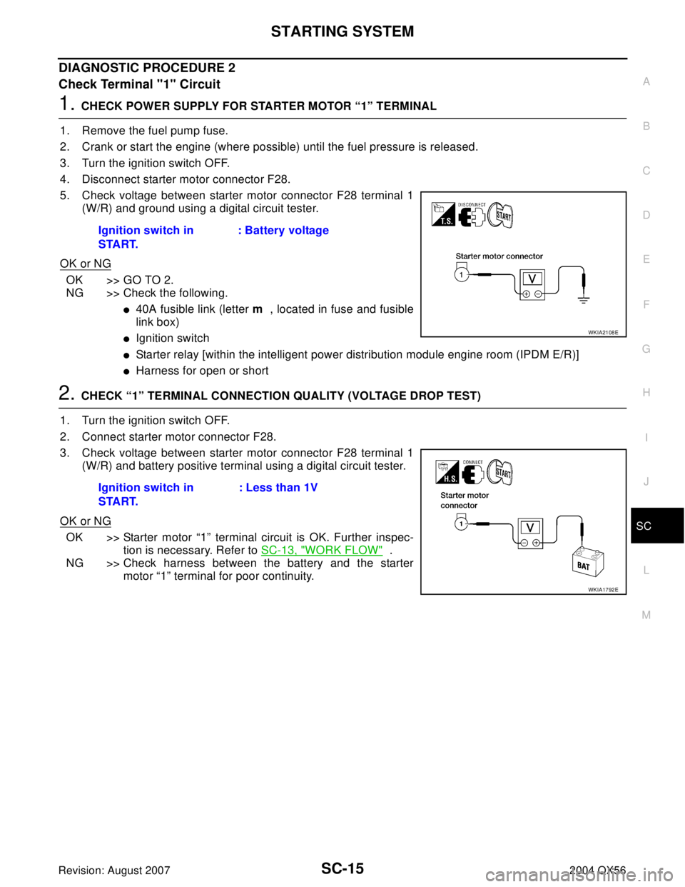
5. Check voltage between starter motor connector F28 terminal 1
(W/R) and ground using a digital circuit tester.
OK or NG
OK >> GO TO 2.
NG >> Check the following.
�40A fusible link (letter m , located in fuse and fusible
link box)
�Ignition switch
�Starter relay [within the intelligent power distribution module engine room (IPDM E/R)]
�Harness for open or short
2. CHECK “1” TERMINAL CONNECTION QUALITY (VOLTAGE DROP TEST)
1. Turn the ignition switch OFF.
2. Connect starter motor connector F28.
3. Check voltage between starter motor connector F28 terminal 1
(W/R) and battery positive terminal using a digital circuit tester.
OK or NG
OK >> Starter motor “1” terminal circuit is OK. Further inspec-
tion is necessary. Refer to SC-13, "
WORK FLOW" .
NG >> Check harness between the battery and the starter
motor “1” terminal for poor continuity. Ignition switch in
START.: Battery voltage
WKIA2108E
Ignition switch in
START.: Less than 1V
WKIA1792E