Page 2824 of 3371
SUNROOF
RF-23
C
D
E
F
G
H
J
K
L
MA
B
RF
Revision: August 20072004 QX56
3. CHECK DOOR SWITCH
Check continuity between each door switch terminal 2 and body ground part of door switch.
OK or NG
OK >> GO TO 4.
NG >> Replace malfunctioning door switch.
4. CHECK BCM OUTPUT SIGNAL
1. Connect BCM connector.
2. Check voltage between BCM connector M18 terminal 12, M19 terminal 47 and ground.
OK or NG
OK >> Check the condition of the harness and the connector.
NG >> Replace BCM. Refer to BCS-19, "
Removal and Installa-
tion of BCM" .
Terminal Condition Continuity
2Body ground part
of door switchDoor switch pushed No
Door switch released Yes
WIIA0289E
12 (R/L) - Ground : Battery voltage
47 (SB) - Ground : Battery voltage
WIIA0234E
Page 2879 of 3371

RSU-20
TROUBLE DIAGNOSIS FOR SELF-DIAGNOSTIC ITEMS
Revision: August 20072004 QX56
5. EXHAUST VALVE SOLENOID INSPECTION
Apply 12V to suspension air compressor C9 terminal 2 and body
ground to suspension air compressor C9 terminal 1.
OK or NG
OK >> GO TO 6.
NG >> Replace the suspension air compressor. Refer to RSU-
42, "REAR LOAD LEVELING AIR SUSPENSION COM-
PRESSOR ASSEMBLY" .
6. CHECK EXHAUST VALVE SOLENOID POWER AND GROUND
1. Reconnect the suspension control unit connector.
2. Turn the ignition switch ON.
3. Check voltage between suspension air compressor connector
C9 terminal 2 (SB) and ground.
4. Turn ignition switch OFF.
5. Check resistance between suspension air compressor connec-
tor C9 terminal 1 (B) and ground.
OK or NG
OK >> Replace the suspension control unit. Refer to RSU-46,
"CONTROL UNIT" .
NG >> Repair the circuit.
Compressor Motor, Compressor Motor Relay and Circuit InspectionEES0011C
INSPECTION PROCEDURE
1. SELF-DIAGNOSIS RESULT CHECK
Check self-diagnosis results.
Is the above displayed in the self-diagnosis display items?
YES >> If code C1802 was retrieved during self-diagnosis, GO TO 3. If code C1804 or C1808 was
retrieved during self-diagnosis, GO TO 2.
NO >> Inspection End.System air pressure should vent.
WEIA0063E
Voltage : Approx. 12V
WEIA0088E
Continuity should exist.
WEIA0089E
Self-diagnosis results
C1802
C1804
C1808
Page 2880 of 3371

TROUBLE DIAGNOSIS FOR SELF-DIAGNOSTIC ITEMS
RSU-21
C
D
F
G
H
I
J
K
L
MA
B
RSU
Revision: August 20072004 QX56
2. CHECK SYSTEM OPERATION
1. Load vehicle to standard laden condition (with driver, front passenger, 2 passengers in second row seats
and no cargo).
2. Conduct active test of "EXHAUST SOLENOID" to lower vehicle ride height to -20mm.
3. Return the rear load leveling air suspension system to normal operating mode.
4. Check self-diagnostic results.
Is code C1804 or C1808 displayed again?
YES >> GO TO 3.
NO >> Inspection End.
3. CONNECTOR INSPECTION
1. Turn ignition switch OFF.
2. Disconnect suspension control unit connector B3 and suspension air compressor C9.
3. Check the terminals for deformation, disconnection, looseness or damage.
OK or NG
OK >> If code C1804 or C1808 was retrieved during self-diagnosis, GO TO 4. If code C1802 was
retrieved during self-diagnosis, GO TO 6.
NG >> Repair or replace as necessary.
4. AIR HOSE INSPECTION
Inspect for pinched or damaged air hoses between the suspension air reservoir and each load leveling rear air
suspension shock absorber.
OK or NG
OK >> GO TO 5.
NG >> Repair or replace as necessary.
5. SUSPENSION AIR COMPRESSOR INSPECTION
Apply 12V to suspension air compressor C9 terminal 2 and body
ground to suspension air compressor C9 terminal 1.
OK or NG
OK >> GO TO 6.
NG >> Replace the suspension air compressor. Refer to RSU-
42, "REAR LOAD LEVELING AIR SUSPENSION COM-
PRESSOR ASSEMBLY" . System air pressure should vent.
WEIA0066E
Page 2892 of 3371
REAR SUSPENSION MEMBER
RSU-33
C
D
F
G
H
I
J
K
L
MA
B
RSU
Revision: August 20072004 QX56
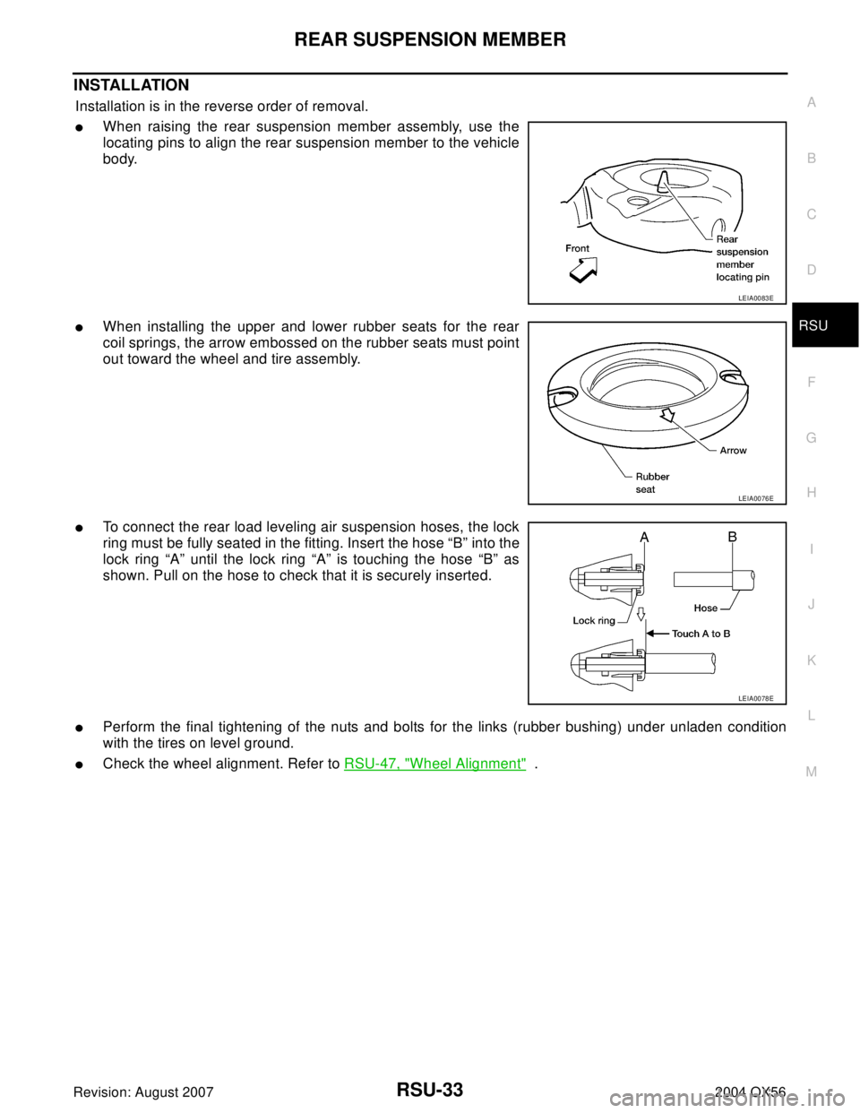
INSTALLATION
Installation is in the reverse order of removal.
�When raising the rear suspension member assembly, use the
locating pins to align the rear suspension member to the vehicle
body.
�When installing the upper and lower rubber seats for the rear
coil springs, the arrow embossed on the rubber seats must point
out toward the wheel and tire assembly.
�To connect the rear load leveling air suspension hoses, the lock
ring must be fully seated in the fitting. Insert the hose “B” into the
lock ring “A” until the lock ring “A” is touching the hose “B” as
shown. Pull on the hose to check that it is securely inserted.
�Perform the final tightening of the nuts and bolts for the links (rubber bushing) under unladen condition
with the tires on level ground.
�Check the wheel alignment. Refer to RSU-47, "Wheel Alignment" .
LEIA0083E
LEIA0076E
LEIA0078E
Page 2902 of 3371
REAR LOAD LEVELING AIR SUSPENSION COMPRESSOR ASSEMBLY
RSU-43
C
D
F
G
H
I
J
K
L
MA
B
RSU
Revision: August 20072004 QX56
5. Remove the four bolts that mount the rear load leveling air sus-
pension compressor assembly to the underbody.
INSTALLATION
Installation is in the reverse order of removal.
�To connect the rear load leveling air suspension hoses, the lock
ring must be fully seated in the fitting. Insert the hose “B” into the
lock ring “A” until the lock ring “A” is touching the hose “B” as
shown. Pull on the hose to check that it is securely inserted.
LEIA0090E
LEIA0078E
Page 2905 of 3371

RSU-46
CONTROL UNIT
Revision: August 20072004 QX56
CONTROL UNITPFP:47850
Removal and InstallationEES0011V
REMOVAL
1. Remove the rear LH interior trim panel. Refer to EI-34, "BODY SIDE TRIM" .
2. Disconnect the battery negative terminal.
3. Disconnect the suspension control unit electrical connector.
4. Remove the two bolts and remove the suspension control unit.
INSTALLATION
Installation is in the reverse order of removal.
Initialization ProcedureEES0011W
1. If control unit has been replaced, proceed to step 2. If control unit has not been replaced, use CONSULT-
II “CLEAR HEIGHT INI” work support function to clear initialization flag and value. The CK SUSP warning
lamp should illuminate. Using CONSULT-II “EXHAUST SOLENOID” active test, release the air pressure
from the rear load leveling air suspension system.
2. Roll vehicle forward and backward.
3. Use CONSULT-II “ADJUST HEIGHT INI” work support function to set initialization condition.
4. Confirm that CK SUSP warning lamp is OFF.
LEIA0100E
Suspension control unit bolts : 6 N·m (0.6 kg-m, 53 in-lb)
Page 2911 of 3371

SB-4
SEAT BELTS
Revision: August 20072004 QX56
REMOVAL OF SEAT BELT RETRACTOR
CAUTION:
�Before servicing SRS, turn the ignition switch off, disconnect both battery cables and wait at least
3 minutes.
1. Remove the center pillar upper/lower finishers. Refer to EI-34, "
BODY SIDE TRIM" .
2. Remove the seat belt retractor anchor bolts and seat belt retractor and belt assembly.
�On RH side, disconnect the seat belt tension sensor.
3. Disconnect the seat belt pre-tensioner electrical connector.
CAUTION:
�For installing/removing seat belt pre-tensioner connector,
insert a thin screwdriver wrapped in tape into the notch, lift
the lock and remove the connector.
�Install the connector with the lock raised, and push the lock
into the connector.
INSTALLATION OF SEAT BELT RETRACTOR
Installation is in the reverse order of removal.
�Install the seat belt retractor and belt assembly upper bolt first.
�Ensure that seat belt height adjuster is locked in the lowest position during installation.
WHIA0237E
PHIA0341E
Page 2931 of 3371

SC-10
STARTING SYSTEM
Revision: August 20072004 QX56
STARTING SYSTEMPFP:23300
System DescriptionEKS00798
Power is supplied at all times:
�through 40A fusible link (letter m , located in the fuse and fusible link box)
�to ignition switch terminal B.
With the ignition switch in the START position, power is supplied:
�from ignition switch terminal ST
�to IPDM E/R terminal 21.
With the ignition switch in the ON or START position, power is supplied to IPDM E/R (intelligent power distribu-
tion module engine room) CPU.
With the selector lever in the P or N position, power is supplied:
�through A/T assembly terminal 9
�to IPDM E/R terminal 48.
Ground is supplied at all times:
�to IPDM E/R terminals 38 and 59
�from body grounds E9, E15 and E24.
Then the starter relay is turned on.
The IPDM E/R is energized and power is supplied:
�from terminal 19 of the IPDM E/R
�to terminal 1 of the starter motor windings.
The starter motor plunger closes and provides a closed circuit between the battery and the starter motor. The
starter motor is grounded to the cylinder block. With power and ground supplied, the starter motor operates.