Page 1699 of 3371

EC-508Revision: August 2007
DTC P1446 EVAP CANISTER VENT CONTROL VALVE
2004 QX56
4. CHECK EVAP CANISTER
Weigh the EVAP canister with the EVAP canister vent control valve and EVAP control system pressure sensor
attached.
The weight should be less than 2.2 kg (4.9 lb).
OK or NG
OK >> GO TO 6.
NG >> GO TO 5.
5. DETECT MALFUNCTIONING PART
Check the following.
�EVAP canister for damage
�EVAP hose between EVAP canister and vehicle frame for clogging or poor connection
>> Repair hose or replace EVAP canister.
6. CHECK EVAP CONTROL SYSTEM PRESSURE SENSOR CONNECTOR
1. Disconnect EVAP control system pressure sensor harness connector.
2. Check connectors for water.
OK or NG
OK >> GO TO 7.
NG >> Replace EVAP control system pressure sensor.
7. CHECK EVAP CONTROL SYSTEM PRESSURE SENSOR
Refer to EC-301, "
Component Inspection" .
OK or NG
OK >> GO TO 8.
NG >> Replace EVAP control system pressure sensor.
8. CHECK INTERMITTENT INCIDENT
Refer to EC-127, "
TROUBLE DIAGNOSIS FOR INTERMITTENT INCIDENT" .
>>INSPECTION END
Component InspectionUBS00HB7
EVAP CANISTER VENT CONTROL VALVE
With CONSULT-II
1. Remove EVAP canister vent control valve from EVAP canister.
2. Check portion B of EVAP canister vent control valve for being
rusted.
If NG, replace EVAP canister vent control valve.
If OK, go to next step.
3. Reconnect harness connectors disconnected.
4. Turn ignition switch ON.Water should not exist.
PBIB1033E
Page 1832 of 3371

EC-641
C
D
E
F
G
H
I
J
K
L
MA
EC
Revision: August 20072004 QX56
Diagnostic ProcedureUBS00HE3
SYMPTOM: FUEL ODOR FROM EVAP CANISTER IS STRONG.
1. CHECK EVAP CAN")
ON BOARD REFUELING VAPOR RECOVERY (ORVR)
EC-641
C
D
E
F
G
H
I
J
K
L
MA
EC
Revision: August 20072004 QX56
Diagnostic ProcedureUBS00HE3
SYMPTOM: FUEL ODOR FROM EVAP CANISTER IS STRONG.
1. CHECK EVAP CANISTER
1. Remove EVAP canister with EVAP canister vent control valve and EVAP control system pressure sensor
attached.
2. Weigh the EVAP canister with EVAP canister vent control valve and EVAP control system pressure sensor
attached.
The weight should be less than 2.2 kg (4.9 lb).
OK or NG
OK >> GO TO 2.
NG >> GO TO 3.
2. CHECK IF EVAP CANISTER SATURATED WITH WATER
Does water drain from the EVAP canister?
Ye s o r N o
Yes >> GO TO 3.
No >> GO TO 5.
3. REPLACE EVAP CANISTER
Replace EVAP canister with a new one.
>> GO TO 4.
4. DETECT MALFUNCTIONING PART
Check the EVAP hose between EVAP canister and vehicle frame for clogging or poor connection.
>> Repair or replace EVAP hose.
5. CHECK REFUELING EVAP VAPOR CUT VALVE
Refer to EC-643, "
Component Inspection" .
OK or NG
OK >>INSPECTION END
NG >> Replace refueling EVAP vapor cut valve with fuel tank.
BBIA0351E
Page 1833 of 3371

2004 QX56
SYMPTOM: CANNOT REFUEL/FUEL ODOR FROM THE FUEL FILLER OPENING IS STRONG
WHILE REFUELING.
1. CHECK EVAP CANISTER
1. Remov")
EC-642Revision: August 2007
ON BOARD REFUELING VAPOR RECOVERY (ORVR)
2004 QX56
SYMPTOM: CANNOT REFUEL/FUEL ODOR FROM THE FUEL FILLER OPENING IS STRONG
WHILE REFUELING.
1. CHECK EVAP CANISTER
1. Remove EVAP canister with EVAP canister vent control valve and EVAP control system pressure sensor
attached.
2. Weigh the EVAP canister with EVAP canister vent control valve and EVAP control system pressure sensor
attached.
The weight should be less than 2.2 kg (4.9 lb).
OK or NG
OK >> GO TO 2.
NG >> GO TO 3.
2. CHECK IF EVAP CANISTER SATURATED WITH WATER
Does water drain from the EVAP canister?
Ye s o r N o
Yes >> GO TO 3.
No >> GO TO 5.
3. REPLACE EVAP CANISTER
Replace EVAP canister with a new one.
>> GO TO 4.
4. DETECT MALFUNCTIONING PART
Check the EVAP hose between EVAP canister and vehicle frame for clogging or poor connection.
>> Repair or replace EVAP hose.
5. CHECK VENT HOSES AND VENT TUBES
Check hoses and tubes between EVAP canister and refueling control valve for clogging, kink, looseness and
improper connection.
OK or NG
OK >> GO TO 6.
NG >> Repair or replace hoses and tubes.
6. CHECK FILLER NECK TUBE
Check recirculation line for clogging, dents and cracks.
OK or NG
OK >> GO TO 7.
NG >> Replace filler neck tube.
BBIA0351E
Page 1957 of 3371

EM-74Revision: August 2007
CYLINDER BLOCK
2004 QX56
* Refer to GI-45, "Recommended Chemical Products and Sealants" .
DISASSEMBLY
1. Remove engine assembly. Refer to EM-70, "REMOVAL" .
2. Remove the drive plate.
�Hold the crankshaft pulley bolt to lock the crankshaft and remove the drive plate bolts.
�Loosen bolts diagonally.
CAUTION:
�Be careful not to damage drive plate. Especially avoid
deforming and damaging of signal plate teeth (circum-
ference position).
�Place the drive plate with signal plate surface facing
other than downward.
�Keep magnetic materials away from signal plate.
3. Lift the engine with hoist to install it onto engine stand. Refer to EM-70, "
REMOVAL" .
CAUTION:
�Use an engine stand that has a load capacity [approximately 240kg (529 lb) or more] large
enough for supporting the engine weight.
�Before removing the hanging chains, make sure the engine stand is stable and there is no risk
of overturning.
�If the load capacity of the stand is not adequate, remove the following parts beforehand to reduce the
potential risk of overturning the stand.
–Remove fuel tube and fuel injector assembly. Refer to EM-29, "REMOVAL" .
–Remove intake manifold. Refer to EM-15, "REMOVAL" .
–Remove exhaust manifold. Refer to EM-19, "REMOVAL" .
–Remove A/C compressor fitting bolts and brackets. Refer to ATC-166, "REMOVAL" .
–Remove ignition coil. Refer to EM-26, "REMOVAL" .
–Remove rocker cover. Refer to EM-33, "REMOVAL" .
–Other removable brackets.
4. Drain engine oil. Refer to MA-16, "
Changing Engine Oil" .
1. Knock sensor sub-harness 2. Knock sensor 3. Cylinder block
4. Main bearing 5. Top ring 6. Second ring
7. Oil ring 8. Crankshaft key 9. Piston
10. Connecting rod 11. Snap ring 12. Piston pin
13. Connecting rod bearing 14. Connecting rod bearing cap 15. Main bearing cap
16. Thrust bearing 17. Main bearing 18. Crankshaft
19. Pilot converter 20. Thrust bearing 21. Side bolt
22. Drive plate 23. Reinforcement plate 24. Rear oil seal retainer
25. Rear oil seal 26. Transmission 27. O-ring
28. Crankshaft position sensor (POS) 29. Gasket 30. Cylinder block heater
31. Connector cap
KBIA2491E
Page 2085 of 3371

GI-4
PRECAUTIONS
Revision: August 20072004 QX56
General PrecautionsEAS00148
�Do not operate the engine for an extended period of time without
proper exhaust ventilation.
Keep the work area well ventilated and free of any flammable
materials. Special care should be taken when handling any flam-
mable or poisonous materials, such as gasoline, refrigerant gas,
etc. When working in a pit or other enclosed area, be sure to
properly ventilate the area before working with hazardous mate-
rials.
Do not smoke while working on the vehicle.
�Before jacking up the vehicle, apply wheel chocks or other tire
blocks to the wheels to prevent the vehicle from moving. After
jacking up the vehicle, support the vehicle weight with safety
stands at the points designated for proper lifting before working
on the vehicle.
These operations should be done on a level surface.
�When removing a heavy component such as the engine or tran-
saxle/transmission, be careful not to lose your balance and drop
them. Also, do not allow them to strike adjacent parts, especially
the brake tubes and master cylinder.
�Before starting repairs which do not require battery power:
Turn off ignition switch.
Disconnect the negative battery terminal.
�If the battery terminals are disconnected, recorded memory of
radio and each control unit is erased.
�Battery posts, terminals and related accessories contain lead
and lead compounds. Wash hands after handling.
�To prevent serious burns:
Avoid contact with hot metal parts.
Do not remove the radiator cap when the engine is hot.
�Dispose of or recycle drained oil or the solvent used for cleaning
parts in an appropriate manner.
�Do not attempt to top off the fuel tank after the fuel pump nozzle
shuts off automatically.
Continued refueling may cause fuel overflow, resulting in fuel
spray and possibly a fire.
�Clean all disassembled parts in the designated liquid or solvent
prior to inspection or assembly.
�Replace oil seals, gaskets, packings, O-rings, locking washers, cotter pins, self-locking nuts, etc. with new
ones.
�Replace inner and outer races of tapered roller bearings and needle bearings as a set.
�Arrange the disassembled parts in accordance with their assembled locations and sequence.
�Do not touch the terminals of electrical components which use microcomputers (such as ECM).
Static electricity may damage internal electronic components.
�After disconnecting vacuum or air hoses, attach a tag to indicate the proper connection.
�Use only the fluids and lubricants specified in this manual.
SGI285
SGI231
SEF 2 89 H
SGI233
Page 2100 of 3371
HOW TO USE THIS MANUAL
GI-19
C
D
E
F
G
H
I
J
K
L
MB
GI
Revision: August 20072004 QX56
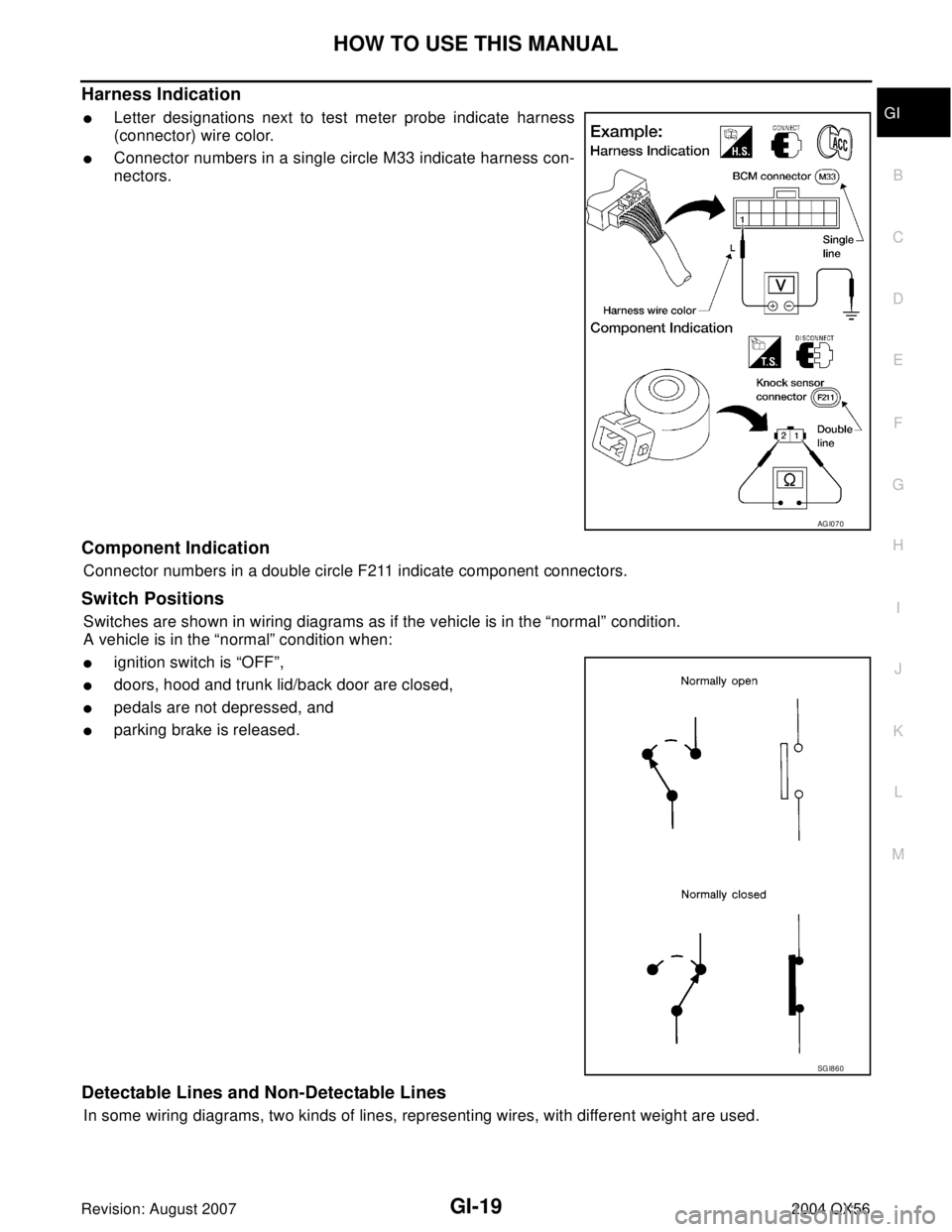
Harness Indication
�Letter designations next to test meter probe indicate harness
(connector) wire color.
�Connector numbers in a single circle M33 indicate harness con-
nectors.
Component Indication
Connector numbers in a double circle F211 indicate component connectors.
Switch Positions
Switches are shown in wiring diagrams as if the vehicle is in the “normal” condition.
A vehicle is in the “normal” condition when:
�ignition switch is “OFF”,
�doors, hood and trunk lid/back door are closed,
�pedals are not depressed, and
�parking brake is released.
Detectable Lines and Non-Detectable Lines
In some wiring diagrams, two kinds of lines, representing wires, with different weight are used.
AGI070
SGI860
Page 2101 of 3371
GI-20
HOW TO USE THIS MANUAL
Revision: August 20072004 QX56
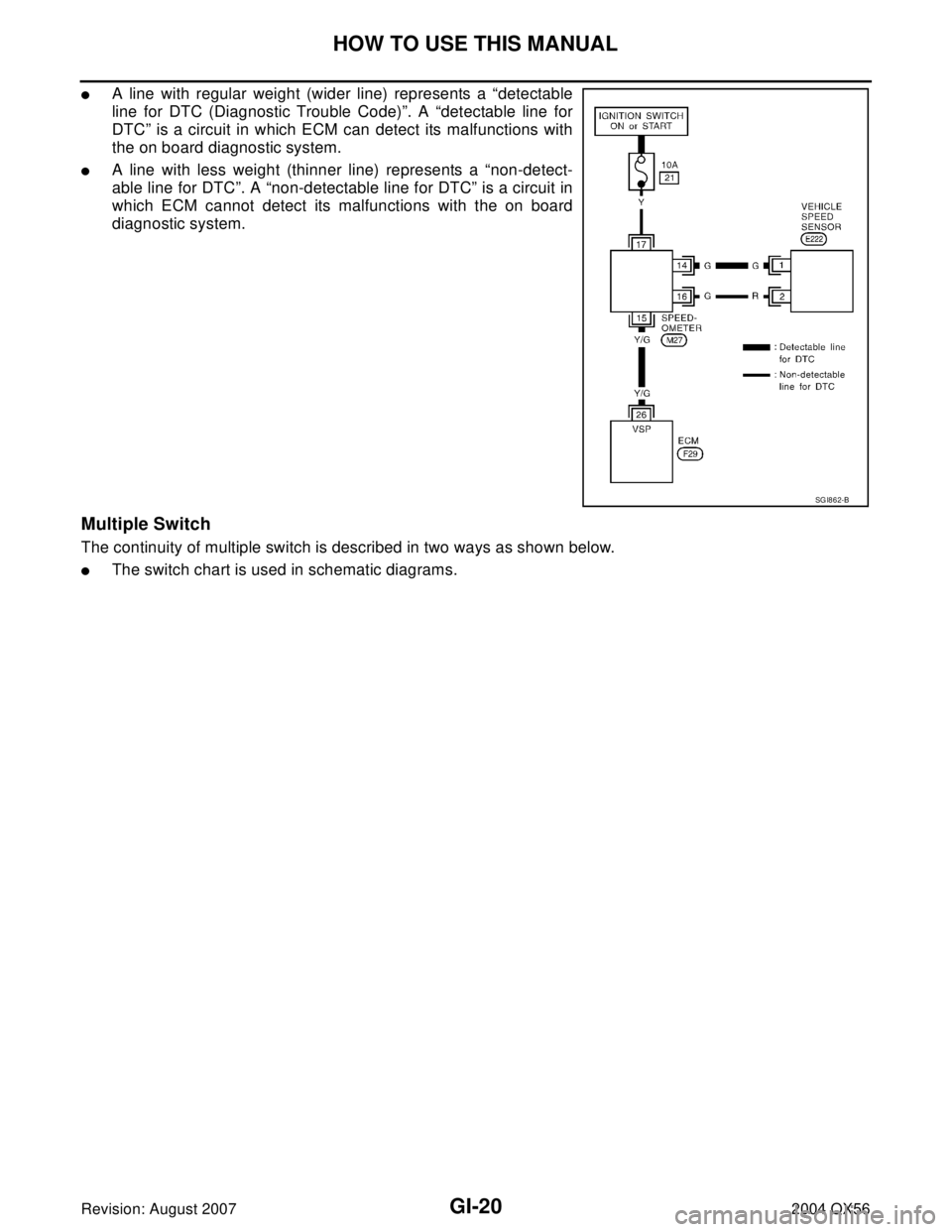
�A line with regular weight (wider line) represents a “detectable
line for DTC (Diagnostic Trouble Code)”. A “detectable line for
DTC” is a circuit in which ECM can detect its malfunctions with
the on board diagnostic system.
�A line with less weight (thinner line) represents a “non-detect-
able line for DTC”. A “non-detectable line for DTC” is a circuit in
which ECM cannot detect its malfunctions with the on board
diagnostic system.
Multiple Switch
The continuity of multiple switch is described in two ways as shown below.
�The switch chart is used in schematic diagrams.
SGI862-B
Page 2462 of 3371
HEADLAMP (FOR USA)
LT-31
C
D
E
F
G
H
I
J
L
MA
B
LT
Revision: August 20072004 QX56
Aiming AdjustmentEKS007A6
For details, refer to the regulations in your state.
Before performing aiming adjustment, check the following.
1. Ensure all tires are inflated to correct pressure.
2. Place vehicle and screen on level surface.
3. Ensure there is no load in vehicle other than the driver (or equivalent weight placed in driver's position).
Coolant and engine oil filled to correct level, and fuel tank full.
4. Confirm spare tire, jack and tools are properly stowed.
5. Confirm headlamp aiming switch is set to "0" (zero) position.
LOW BEAM AND HIGH BEAM
NOTE:
Aim each headlamp individually and ensure other headlamp beam pattern is blocked from screen.
1. Turn headlamp low beam on.
2. Use adjusting screw to perform aiming adjustment.
WKIA1859E

LT-31
C
D
E
F
G
H
I
J
L
MA
B
LT
Revision: August 20072004 QX56
Aiming AdjustmentEKS007A6
For details, refer to the regulations in your state.
Before performing aiming adjustment, ch")