Page 2227 of 3371
GW-92
REAR WINDOW DEFOGGER
Revision: August 20072004 QX56
Rear Window Defogger Circuit CheckEIS002VZ
1. CHECK REAR WINDOW DEFOGGER POWER SUPPLY CIRCUIT
1. Turn ignition switch OFF.
2. Disconnect rear window defogger.
3. Turn ignition switch ON.
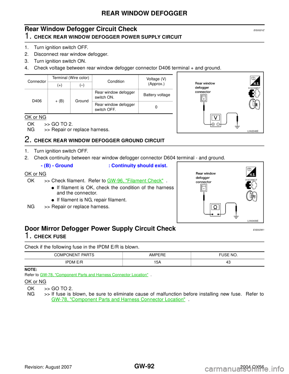
4. Check voltage between rear window defogger connector D406 terminal + and ground.
OK or NG
OK >> GO TO 2.
NG >> Repair or replace harness.
2. CHECK REAR WINDOW DEFOGGER GROUND CIRCUIT
1. Turn ignition switch OFF.
2. Check continuity between rear window defogger connector D604 terminal - and ground.
OK or NG
OK >> Check filament. Refer to GW-96, "Filament Check" .
�If filament is OK, check the condition of the harness
and the connector.
�If filament is NG, repair filament.
NG >> Repair or replace harness.
Door Mirror Defogger Power Supply Circuit CheckEIS002W1
1. CHECK FUSE
Check if the following fuse in the IPDM E/R is blown.
NOTE:
Refer to GW-78, "
Component Parts and Harness Connector Location" .
OK or NG
OK >> GO TO 2.
NG >> If fuse is blown, be sure to eliminate cause of malfunction before installing new fuse. Refer to
GW-78, "
Component Parts and Harness Connector Location" .
ConnectorTerminal (Wire color)
ConditionVoltage (V)
(Approx.)
(+) (–)
D406 + (B) GroundRear window defogger
switch ON. Battery voltage
Rear window defogger
switch OFF.0
LIIA2048E
- (B) - Ground : Continuity should exist.
LIIA0409E
COMPONENT PARTS AMPERE FUSE NO.
IPDM E/R 15A 43
Page 2228 of 3371
REAR WINDOW DEFOGGER
GW-93
C
D
E
F
G
H
J
K
L
MA
B
GW
Revision: August 20072004 QX56
2. CHECK DOOR MIRROR DEFOGGER POWER SUPPLY CIRCUIT 2
1. Turn ignition switch ON.
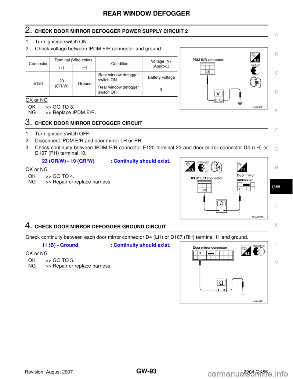
2. Check voltage between IPDM E/R connector and ground.
OK or NG
OK >> GO TO 3.
NG >> Replace IPDM E/R.
3. CHECK DOOR MIRROR DEFOGGER CIRCUIT
1. Turn ignition switch OFF.
2. Disconnect IPDM E/R and door mirror LH or RH.
3. Check continuity between IPDM E/R connector E120 terminal 23 and door mirror connector D4 (LH) or
D107 (RH) terminal 10.
OK or NG
OK >> GO TO 4.
NG >> Repair or replace harness.
4. CHECK DOOR MIRROR DEFOGGER GROUND CIRCUIT
Check continuity between each door mirror connector D4 (LH) or D107 (RH) terminal 11 and ground.
OK or NG
OK >> GO TO 5.
NG >> Repair or replace harness.
ConnectorTerminal (Wire color)
ConditionVoltage (V)
(Approx.)
(+) (–)
E12023
(GR/W)GroundRear window defogger
switch ON Battery voltage
Rear window defogger
switch OFF0
LIIA2049E
23 (GR/W) - 10 (GR/W) : Continuity should exist.
WIIA0527E
11 (B) - Ground : Continuity should exist.
LIIA1454E
Page 2229 of 3371
GW-94
REAR WINDOW DEFOGGER
Revision: August 20072004 QX56
5. CHECK DOOR MIRROR DEFOGGER
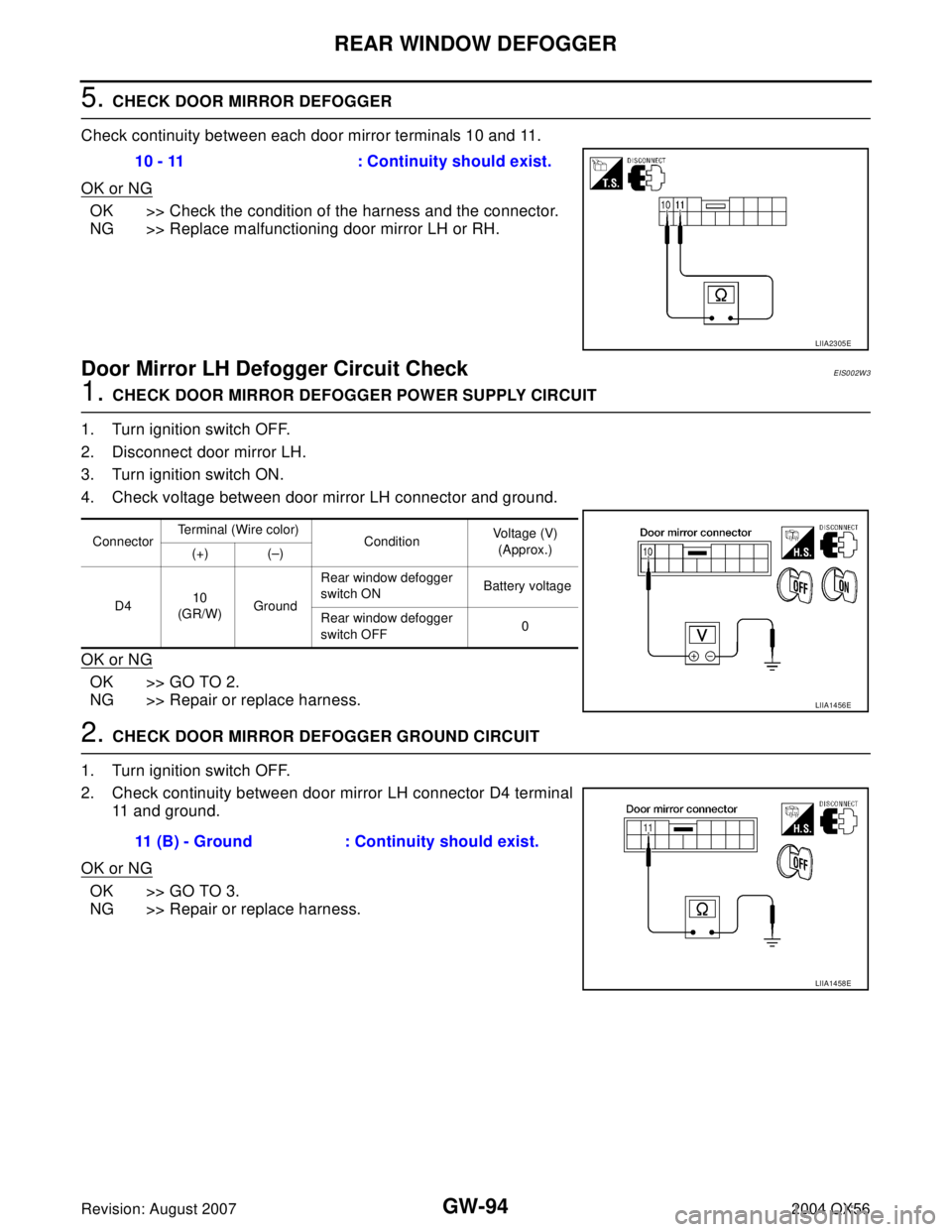
Check continuity between each door mirror terminals 10 and 11.
OK or NG
OK >> Check the condition of the harness and the connector.
NG >> Replace malfunctioning door mirror LH or RH.
Door Mirror LH Defogger Circuit CheckEIS002W3
1. CHECK DOOR MIRROR DEFOGGER POWER SUPPLY CIRCUIT
1. Turn ignition switch OFF.
2. Disconnect door mirror LH.
3. Turn ignition switch ON.
4. Check voltage between door mirror LH connector and ground.
OK or NG
OK >> GO TO 2.
NG >> Repair or replace harness.
2. CHECK DOOR MIRROR DEFOGGER GROUND CIRCUIT
1. Turn ignition switch OFF.
2. Check continuity between door mirror LH connector D4 terminal
11 and ground.
OK or NG
OK >> GO TO 3.
NG >> Repair or replace harness.10 - 11 : Continuity should exist.
LIIA2305E
ConnectorTerminal (Wire color)
ConditionVoltage (V)
(Approx.)
(+) (–)
D410
(GR/W)GroundRear window defogger
switch ON Battery voltage
Rear window defogger
switch OFF0
LIIA1456E
11 (B) - Ground : Continuity should exist.
LIIA1458E
Page 2230 of 3371
REAR WINDOW DEFOGGER
GW-95
C
D
E
F
G
H
J
K
L
MA
B
GW
Revision: August 20072004 QX56
3. CHECK DOOR MIRROR DEFOGGER
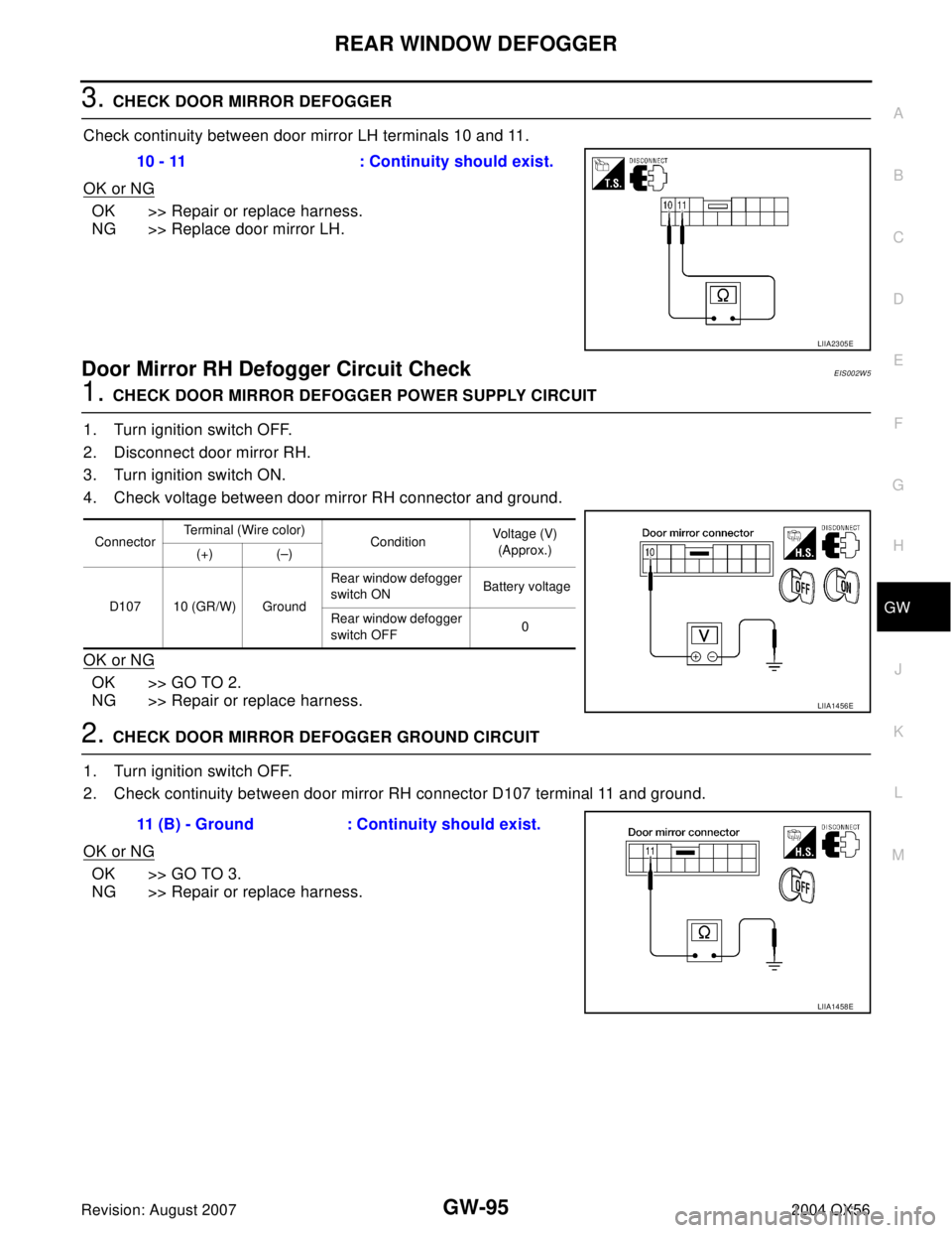
Check continuity between door mirror LH terminals 10 and 11.
OK or NG
OK >> Repair or replace harness.
NG >> Replace door mirror LH.
Door Mirror RH Defogger Circuit CheckEIS002W5
1. CHECK DOOR MIRROR DEFOGGER POWER SUPPLY CIRCUIT
1. Turn ignition switch OFF.
2. Disconnect door mirror RH.
3. Turn ignition switch ON.
4. Check voltage between door mirror RH connector and ground.
OK or NG
OK >> GO TO 2.
NG >> Repair or replace harness.
2. CHECK DOOR MIRROR DEFOGGER GROUND CIRCUIT
1. Turn ignition switch OFF.
2. Check continuity between door mirror RH connector D107 terminal 11 and ground.
OK or NG
OK >> GO TO 3.
NG >> Repair or replace harness.10 - 11 : Continuity should exist.
LIIA2305E
ConnectorTerminal (Wire color)
ConditionVoltage (V)
(Approx.)
(+) (–)
D107 10 (GR/W) GroundRear window defogger
switch ON Battery voltage
Rear window defogger
switch OFF0
LIIA1456E
11 (B) - Ground : Continuity should exist.
LIIA1458E
Page 2231 of 3371
GW-96
REAR WINDOW DEFOGGER
Revision: August 20072004 QX56
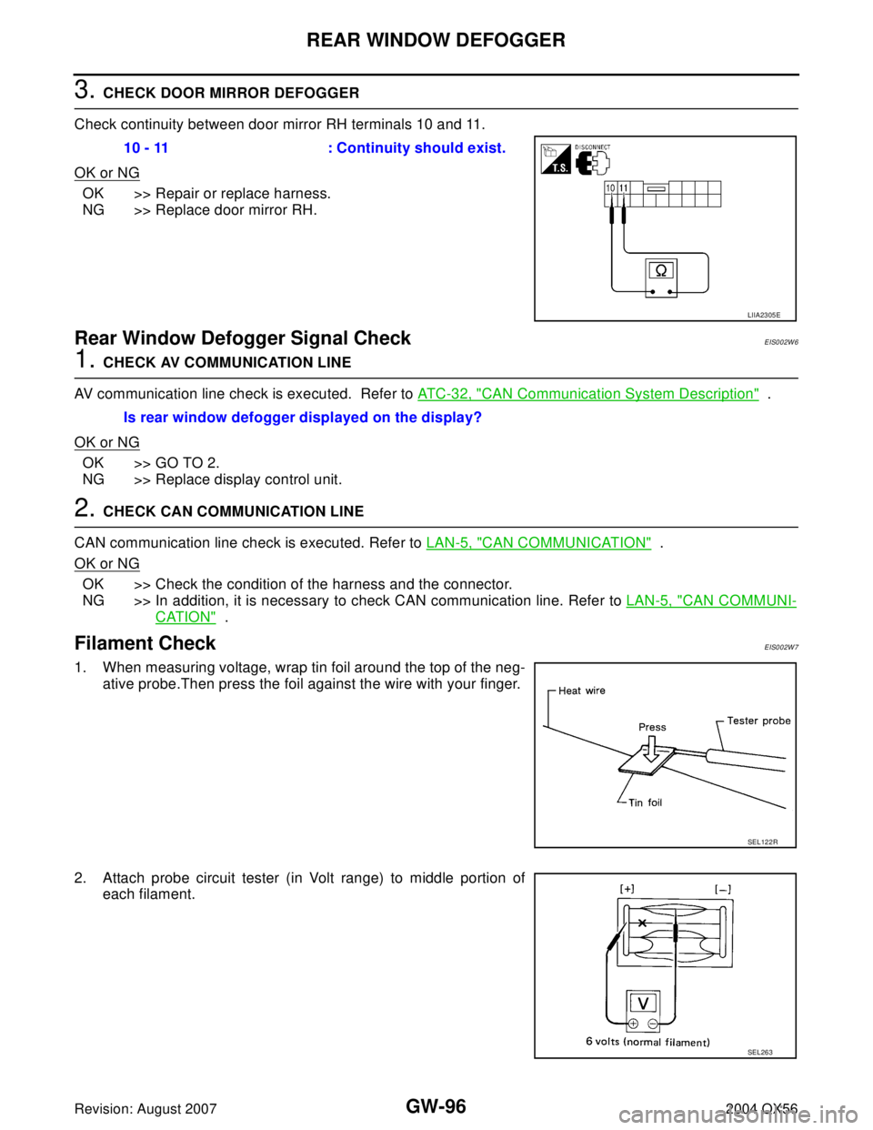
3. CHECK DOOR MIRROR DEFOGGER
Check continuity between door mirror RH terminals 10 and 11.
OK or NG
OK >> Repair or replace harness.
NG >> Replace door mirror RH.
Rear Window Defogger Signal CheckEIS002W6
1. CHECK AV COMMUNICATION LINE
AV communication line check is executed. Refer to AT C - 3 2 , "
CAN Communication System Description" .
OK or NG
OK >> GO TO 2.
NG >> Replace display control unit.
2. CHECK CAN COMMUNICATION LINE
CAN communication line check is executed. Refer to LAN-5, "
CAN COMMUNICATION" .
OK or NG
OK >> Check the condition of the harness and the connector.
NG >> In addition, it is necessary to check CAN communication line. Refer to LAN-5, "
CAN COMMUNI-
CATION" .
Filament CheckEIS002W7
1. When measuring voltage, wrap tin foil around the top of the neg-
ative probe.Then press the foil against the wire with your finger.
2. Attach probe circuit tester (in Volt range) to middle portion of
each filament.10 - 11 : Continuity should exist.
LIIA2305E
Is rear window defogger displayed on the display?
SEL122R
SEL263
Page 2234 of 3371
DOOR MIRROR
GW-99
C
D
E
F
G
H
J
K
L
MA
B
GW
Revision: August 20072004 QX56
DOOR MIRRORPFP:96301
Wiring Diagram — MIRROR —EIS002W9
WIWA0641E
Page 2235 of 3371
GW-100
DOOR MIRROR
Revision: August 20072004 QX56
Door Mirror AssemblyEIS002WA
REMOVAL
NOTE:
Be careful not to damage the mirror bodies.
1. Remove the front door sash cover. Refer to AV- 4 6 , "
Removal and Installation of Front Tweeter" .
2. Remove the door mirror harness connector.
3. Remove the door mirror mounting nuts and the mirror assembly.
INSTALLATION
Installation is in the reverse order of removal.
Door Mirror GlassEIS002WB
REMOVAL
1. Set mirror assembly mirror glass upward.
2. Apply protective tape to mirror housing.
3. Insert a screwdriver at notch and gently pry mirror glass and
holder from mirror holder bracket.
4. Disconnect two electrical connectors from mirror glass and
holder.
LIIA1570E
LIIA1591E
Page 2236 of 3371
DOOR MIRROR
GW-101
C
D
E
F
G
H
J
K
L
MA
B
GW
Revision: August 20072004 QX56
INSTALLATION
1. Set mirror holder bracket and mirror glass and holder in the hor-
izontal position.
2. Connect two electrical connectors to the back of the mirror
holder.
3. Align mirror glass and holder with mirror holder bracket and
push mirror glass and holder onto mirror holder bracket.
4. Rotate mirror to ensure proper installation.
LIIA1592E