Page 2137 of 3371

GW-2Revision: August 20072004 QX56 Rear Power Window Switch LH or RH Power Supply
and Ground Circuit Check ...................................... 58
Rear Power Window Motor LH Circuit Check ......... 58
Rear Power Window Motor RH Circuit Check ........ 59
Limit Switch Circuit Check Rear LH and RH ........... 60
Encoder Circuit Check Rear LH or RH ................... 62
Power Window Serial Link Check Rear LH or RH ... 64
Rear Power Vent Window Switch Circuit Check ..... 65
Rear Power Vent Window Motor LH Circuit Check ... 65
Rear Power Vent Window Motor RH Circuit Check ... 66
Rear Power Vent Window Relay (OPEN) Check .... 66
Rear Power Vent Window Relay (CLOSE) Check ... 67
FRONT DOOR GLASS AND REGULATOR ............. 69
Removal and Installation ........................................ 69
FRONT DOOR GLASS ....................................... 69
FRONT DOOR GLASS REGULATOR ................ 70
FITTING INSPECTION AND SETTING AFTER
INSTALLATION .................................................... 70
REAR DOOR GLASS AND REGULATOR ............... 72
Removal and Installation ........................................ 72
REAR DOOR GLASS .......................................... 72
REAR DOOR GLASS REGULATOR ................... 73
SIDE WINDOW GLASS ............................................ 75
Removal and Installation ........................................ 75
REMOVAL ........................................................... 75
INSTALLATION .................................................... 75
INSIDE MIRROR ....................................................... 76
Wiring Diagram — I/MIRR — ................................. 76
Removal and Installation ........................................ 77
INSIDE MIRROR ................................................. 77
REAR WINDOW DEFOGGER .................................. 78
Component Parts and Harness Connector Location ... 78
System Description ................................................. 79CAN Communication System Description ..............80
Schematic ...............................................................81
Wiring Diagram — DEF — ......................................82
Terminal and Reference Value for BCM ..................85
Terminal and Reference Value for IPDM E/R ..........85
Work Flow ...............................................................85
CONSULT-II Function (BCM) ..................................86
CONSULT-II BASIC OPERATION PROCEDURE
...86
DATA MONITOR ..................................................87
ACTIVE TEST ......................................................87
Trouble Diagnoses Symptom Chart ........................87
BCM Power Supply and Ground Circuit Check ......89
Rear Window Defogger Switch Circuit Check .........90
Rear Window Defogger Power Supply Circuit
Check ......................................................................91
Rear Window Defogger Circuit Check ....................92
Door Mirror Defogger Power Supply Circuit Check ...92
Door Mirror LH Defogger Circuit Check ..................94
Door Mirror RH Defogger Circuit Check .................95
Rear Window Defogger Signal Check ....................96
Filament Check .......................................................96
Filament Repair .......................................................97
REPAIR EQUIPMENT .........................................97
REPAIRING PROCEDURE .................................97
DOOR MIRROR .........................................................99
Wiring Diagram — MIRROR — ..............................99
Door Mirror Assembly ........................................... 100
REMOVAL .......................................................... 100
INSTALLATION .................................................. 100
Door Mirror Glass .................................................. 100
REMOVAL .......................................................... 100
INSTALLATION .................................................. 101
Page 2146 of 3371

WINDSHIELD GLASS
GW-11
C
D
E
F
G
H
J
K
L
MA
B
GW
Revision: August 20072004 QX56
WINDSHIELD GLASSPFP:72712
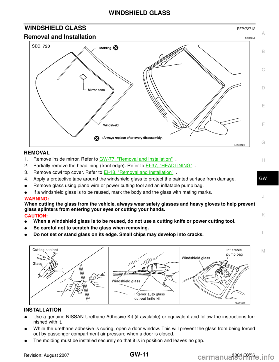
Removal and InstallationEIS002UL
REMOVAL
1. Remove inside mirror. Refer to GW-77, "Removal and Installation" .
2. Partially remove the headlining (front edge). Refer to EI-37, "
HEADLINING" .
3. Remove cowl top cover. Refer to EI-18, "
Removal and Installation" .
4. Apply a protective tape around the windshield glass to protect the painted surface from damage.
�Remove glass using piano wire or power cutting tool and an inflatable pump bag.
�If a windshield glass is to be reused, mark the body and the glass with mating marks.
WA RN ING:
When cutting the glass from the vehicle, always wear safety glasses and heavy gloves to help prevent
glass splinters from entering your eyes or cutting your hands.
CAUTION:
�When a windshield glass is to be reused, do not use a cutting knife or power cutting tool.
�Be careful not to scratch the glass when removing.
�Do not set or stand glass on its edge. Small chips may develop into cracks.
INSTALLATION
�Use a genuine NISSAN Urethane Adhesive Kit (if available) or equivalent and follow the instructions fur-
nished with it.
�While the urethane adhesive is curing, open a door window. This will prevent the glass from being forced
out by passenger compartment air pressure when a door is closed.
�The molding must be installed securely so that it is in position and leaves no gap.
LIIA0652E
PIIA0186E
Page 2211 of 3371
GW-76
INSIDE MIRROR
Revision: August 20072004 QX56
INSIDE MIRRORPFP:96321
Wiring Diagram — I/MIRR —EIS002VK
WIWA1146E
Page 2212 of 3371
INSIDE MIRROR
GW-77
C
D
E
F
G
H
J
K
L
MA
B
GW
Revision: August 20072004 QX56
Removal and InstallationEIS002VL
INSIDE MIRROR
1. Remove inside mirror finisher.
2. Slide the mirror upward to remove.
3. Disconnect the connector.
Installation is in the reverse order of removal.
1. Inside mirror 2. Inside mirror finisher
SIIA0828E
Page 2213 of 3371
GW-78
REAR WINDOW DEFOGGER
Revision: August 20072004 QX56
REAR WINDOW DEFOGGERPFP:25350
Component Parts and Harness Connector LocationEIS002VM
1. IPDM E/R fuse layout 2. Fuse block (J/B) 3. Fuse and fusible link box
4. Fuse and relay box 5. Data link connector M22 6. BCM M18, M20
7. Front air control M49, M50 8. A. Rear window deffoger ground
connector D504
B. Rear window defogger connector
D4069. IPDM E/R E118, E120, E122, E124
10. Door miiror LH D4, door mirror RH
D107
LIIA2304E
Page 2214 of 3371

REAR WINDOW DEFOGGER
GW-79
C
D
E
F
G
H
J
K
L
MA
B
GW
Revision: August 20072004 QX56
System DescriptionEIS002VN
The rear window defogger system is controlled by BCM (body control module) and IPDM E/R (intelligent
power distribution module engine room).
The rear window defogger operates only for approximately 15 minutes.
Power is supplied at all times
�through 15A fuses (No. 43, 46, and 47, located in the IPDM E/R)
�to rear window defogger relay terminals 3 and 6 (located in the IPDM E/R)
�through 50A fusible link (letter f , located in the fuse and fusible link box)
�to BCM terminal 70.
With the ignition switch turned to ON or START position,
Power is supplied
�through ignition switch
�to rear window defogger relay (located in the IPDM E/R)
�through 10A fuse (No. 59, located in the fuse and relay box)
�to BCM terminal 38
�through 10A fuse [No. 8, located in the fuse block (J/B)]
�to front air control terminal 14.
Ground is supplied
�to BCM terminal 67
�to front air control terminal 1
�through body grounds M57, M61 and M79
�to IPDM E/R terminals 38 and 59
�through body grounds E9, E15 and E24.
When front air control (rear window defogger switch) is turned to ON,
Ground is supplied
�to BCM terminal 9
�through front air control terminal 11
�through front air control terminal 1
�through body grounds M57, M61 and M79.
Then rear window defogger switch is illuminated.
Then BCM recognizes that rear window defogger switch is turned to ON.
Then it sends rear window defogger switch signals to IPDM E/R and display control unit via DATA LINE (CAN-
H, CAN-L).
When display control unit receives rear window defogger switch signals, and displays on the screen.
When IPDM E/R receives rear window defogger switch signals,
Ground is supplied
�to rear window defogger relay (located in the IPDM E/R)
�through IPDM E/R terminal 38
�through IPDM E/R terminal 59
�through body grounds E9, E15 and E24.
Then rear window defogger relay is energized.
With power and ground supplied, rear window defogger filaments heat and defog the rear window.
When rear window defogger relay is turned to ON,
Power is supplied
�through heated mirror relay (located in the IPDM E/R)
�through IPDM E/R terminal 23
�to door mirror defogger (LH and RH) terminal 10.
Door mirror defogger (LH and RH) is grounded through body grounds M57, M61 and M79.
With power and ground supplied, rear window defogger filaments heat and defog the rear window and door
mirror defogger filaments heat and defog the mirror.
Page 2222 of 3371

REAR WINDOW DEFOGGER
GW-87
C
D
E
F
G
H
J
K
L
MA
B
GW
Revision: August 20072004 QX56
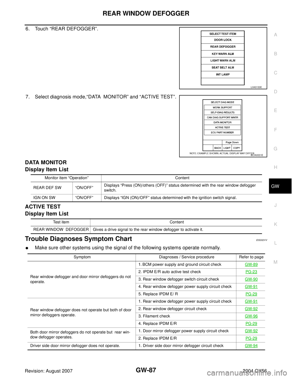
6. Touch “REAR DEFOGGER”.
7. Select diagnosis mode,“DATA MONITOR” and “ACTIVE TEST”.
DATA MONITOR
Display Item List
ACTIVE TEST
Display Item List
Trouble Diagnoses Symptom ChartEIS002VV
�Make sure other systems using the signal of the following systems operate normally.
LIIA0153E
BCIA0031E
Monitor item “Operation” Content
REAR DEF SW “ON/OFF”Displays “Press (ON)/others (OFF)” status determined with the rear window defogger
switch.
IGN ON SW “ON/OFF” Displays “IGN (ON)/OFF” status determined with the ignition switch signal.
Test item Content
REAR WINDOW DEFOGGER Gives a drive signal to the rear window defogger to activate it.
Symptom Diagnoses / Service procedure Refer to page
Rear window defogger and door mirror defoggers do not
operate.1. BCM power supply and ground circuit checkGW-89
2. IPDM E/R auto active test checkPG-23
3. Rear window defogger switch circuit checkGW-90
4. Rear window defogger power supply circuit checkGW-91
5. Replace IPDM E/ RPG-29
Rear window defogger does not operate but both of door
mirror defoggers operate.1. Rear window defogger power supply circuit checkGW-912. Rear window defogger circuit checkGW-92
3. Filament checkGW-96
4. Replace IPDM E/RPG-29
Both door mirror defoggers do not operate but rear win-
dow defogger operates.1. Door mirror defogger power supply circuit checkGW-92
2. Replace IPDM E/RPG-29
Driver side door mirror defogger does not operate. 1. Driver side door mirror defogger circuit checkGW-94
Page 2223 of 3371
GW-88
REAR WINDOW DEFOGGER
Revision: August 20072004 QX56
Passenger side door mirror defogger does not operate. 1. Passenger side door mirror defogger circuit checkGW-95
Rear window defogger switch does not light, and rear win-
dow defogger is not displayed on the display.
But rear window defogger operates. 1. Rear window defogger signal checkGW-96
Symptom Diagnoses / Service procedure Refer to page